

Pressure independent, sometimes referred to as automatic, balancing valves are the next step in the evolution of simplified sizing and selection.
PIBV valves are also sometimes called “automatic” or “dynamic” balancing valves. They are designed to maintain a constant preset flow rate, even when the differential pressure across the valves varies over a wide range. They rely on an internal compensating mechanism to adjust an orifice within the valve so that a calibrated flow rate is maintained within a listed tolerance, typically +/- 10% of the calibrated flow rating. Figure 4-1a shows one body style used for PIBVs.

The internal components in a pressure-independent balancing valve consist of a cylinder, a spring-loaded piston, and a combination of fixed and variable-shaped orifices through which flow passes. The assembly of these components is called the “cartridge” of the PIBV. An example of such a cartridge is seen in Figure 4-1b.

A Y-pattern PIBV is shown in Figure 4-2a. It uses the same type of pressure-regulating cartridge as the valve shown in Figure 4-1a. The Y-pattern valve also allows installers to easily change the cartridge if the design flow rate specification changes. The cartridge can also be removed when the system is being flushed, and then reinstalled.

One example would be a replacement scenario for a hydronic fan coil, wherein the unit being replaced required 2 gpm, but the new unit only requires 1 gpm. Another example would be if panel radiators were retrofitted into a branch circuit to provide heat for a building addition. The original branch flow rate of 2 gpm might not be sufficient, so it could be replaced with a cartridge having a higher flow rate calibration.
The flow cartridge within a PIBV is composed of a cylinder, a spring-loaded piston, and a combination of fixed and variable geometric orifices through which the fluid flows. These variable orifice sizes increase or decrease by the piston movement, contingent on the system's fluid thrust. A specially calibrated spring counteracts this movement to regulate the amount of fluid that will pass through the valve orifices, maintaining a constant flow rate in the circuit.
Pressure Independent Balancing Valve Operation

At low differential pressures (less than 2, 4, or 5 psi, depending on valve model), the internal compensating mechanism does not move. This allows the maximum free flow passage through the valve. Flow passes through both the fixed and variable orifices. At such low differential pressures, the internal mechanism cannot adjust to maintain a fixed flow rate. Thus, flow rate through the valve will increase as differential pressure increases. The “inactive” position of the internal cartridge is shown in Figure 4-3.
If the differential pressure across the PIBV exceeds the minimum threshold pressure of 2, 4 or 5 psi (depending on valve model), the internal piston assembly begins to move in the direction of flow due to thrust against it. An internal spring is partially compressed by this action. Under this condition, the piston partially obstructs the tapered slot through which flow must pass. However, the flow passage is now automatically adjusted so that the valve can maintain its calibrated flow rate at the higher differential pressure.

As the thrust and the differential pressure across the valve continues to increase, the piston moves farther to compress the spring. This movement continues to reduce the flow passage through the tapered orifice, as seen in Figure 4-4. The change in the orifice size is such that the valve continues to deliver its calibrated flow rate under the higher differential pressure.
This ability to adjust flow through the tapered orifice remains in effect until the differential pressure across the valve reaches an upper threshold limit of 14, 32, 34 or 35 psi (depending on valve model).

Such high differential pressure is relatively uncommon in most well-designed hydronic systems that include some means of differential pressure control.
If the differential pressure across the valve does exceed the upper pressure threshold, the piston and counterbalancing spring can no longer maintain the calibrated flow rate. The piston’s position completely blocks flow through the tapered orifice. All flow must now pass through the fixed orifice. This condition is shown in Figure 4-5. The result will be an increase in flow rate if differential pressure increases above the upper pressure threshold.

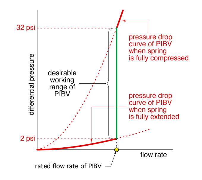
The overall flow versus differential pressure characteristics of a PIBV is shown in Figure 4-6. The desired condition is to maintain the differential pressure across the valve between the lower and upper threshold values, so that the internal cartridge remains active and the valve maintains its calibrated flow rate.
With a PIBV in each branch, and as long as the differential pressure across that valve remains within the regulation range of the valve, the flow rate through each active branch remains at the calibrated value of the PIBV, regardless of the flow status in other branches. This is a significant benefit of a PIBV valve compared to a manually set balancing valve.
Pressure Independent Balancing Valve Applications

Figure 4-7a/b compares the flow rate changes in two systems that are identical other than the type of balancing valves used.
The system in Figure 4-7a uses manual balancing valves that have been adjusted so that the desired flow rates exist in each branch, provided all branches are active. However, when a zone valve in one of the branches closes, the flow rates in the other branches increase due to the increased differential pressure created by the fixed-speed circulator. This change in flow rates is undesirable because it increases heat output from the heat emitters.

The system in Figure 4-7b uses PIBVs in each branch. Each valve has been configured with a flow cartridge for the design flow rate of its branch. When one of the zone valves closes, the PIBVs in the other branches immediately compensate for the increased differential pressure so that the flow through each active branch remains the same.
The cartridges within each active PIBV absorb the increased head energy from the circulator when the operating point moves to the left and up on the pump curve.
PIBV valves are a significant advancement in balancing technology. They provide a way to hold a stable flow rate in different branches of the system as the hydraulic resistances of other branches change.
The unique polymer cartridges used in all Caleffi PIBVs are specifically designed to prevent potential noise due to low flow.
To preserve the performance of PIBVs, the system should be free of small debris that could deposit on the slots used in the calibrated pressure-regulating cartridges. To minimize this possibility, all systems using PIBV should also have a high-efficiency dirt separator, such as a Caleffi DIRTMAG® PRO.
Pressure Independent Balancing Valve Sizing

To properly specify a PIBV, the following variables must be determined:
- Required flow rate
- The range of $\Delta P$ that could be imposed on the PIBV
- Branch pipe size
- Type of connection (press, sweat, NPT, PEX expansion, PEX crimp, etc.)
Figure 4-8 shows ratings for Caleffi 128 series PIBVs.
In this example, a 128556AF 1G5 would denote a ¾" press connection and 1.50 gpm control range with a $\Delta P$ control range of 2-32 psi.
Strengths & Limitations Of Pressure Independent Balancing Valves
Strengths:
- Holds consistent branch flow rates by compensating for changes in differential pressure caused by zone valves opening and closing
- Less labor required for commissioning
Limitations:
- In the event of a heat emitter changeout/modification, a cartridge replacement might be required
- Circulator sizing must ensure that the differential pressure across the PIBV stays within the active range of the valve's internal cartridge
- System fluid needs to be clean to ensure the internal cartridge is not clogged