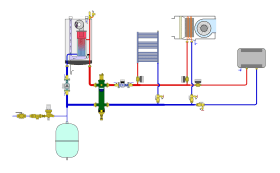
Many hydronic heating and cooling systems have multiple branches that serve different heat emitters or cooling coils. The heat emitters or cooling coils can have different flow rate requirements. They can also have very different pressure drop characteristics. The location of the branches within the system relative to the circulator can vary widely, as can the pipe and fitting sizes connecting them to the system. Figure 1-1 shows an example of a heating system with all of the above variations.
In a multi-branch system, the flow rate through each branch depends upon the hydraulic resistance of that branch relative to the others. Branches with lower hydraulic resistance will have higher flow rates relative to branches with higher hydraulic resistance.
Although it is possible to estimate the flow rate that will occur “naturally” in each branch, there is no guarantee that those flow rates would be properly matched to the flow requirements of each heat emitter or cooling coil. Such a system could be described as “unbalanced.” In that state, it is unlikely that the amount of thermal energy transferred at each branch will be matched to the thermal load associated with that branch. This will likely result in discomfort, wasted energy, objectionable noise, and even potential damage to components exposed to excessively high flow rates.
A NATURALLY UNBALANCED SYSTEM
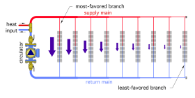
Figure 1-2 shows an example of a multi-branch piping system in which each branch is assumed to have the same piping, fittings and heat emitter.
The arrows adjacent to each branch represent the flow rate through that branch. The hydraulic resistance of the branch closest to the circulator, combined with the resistance through the supply and return mains up to the first branch, is lower than that of the next branch out, and so forth.
This allows the flow rate through the first branch to be a higher percentage of the total system flow rate. The farther removed the remaining branches are from the circulator, the lower their flow rate.
Allowing the system to operate in this “natural” state can lead to excessive heating or cooling in some areas of the building, with the other objectionable symptoms of imbalance described in the previous section.
Designers and installers can use balancing valves to adjust the hydraulic resistance of each branch to ensure that the proper rate of heat transfer passes through each branch.
Imagine a track race, in which all runners start on the same line across the width of the track. The runners are told they must stay in their respective lanes during the race. The runner on the innermost lane will have the shortest distance to the finish line. The runner in the next lane out will have the next shortest distance, and so forth. Such a situation is inherently unfair since each runner has a different distance to get to the finish line.
To prevent this inequity, the runners start at staggered points meant to provide the same distance along each lane from the starting point to the finish line. This “balances” the distance, so that runners moving at the exact same speed would reach the finish line at the same time. It removes the inherent unfairness of one runner moving along the inner lane while the other runners have longer paths to the finish line. This is analogous to a situation in which a hydronic system has several branches of differing lengths, and the designer's intent is to have the same flow rate in each branch.
The branches having shorter lengths have the “advantage” of lower hydraulic resistance and will receive a higher percentage of the total system flow rate, relative to the longer branches. Higher flow rates typically result in higher rates of heat transfer. This is a classic “unbalanced” system that needs to be balanced.
The goals of proper hydronic system balancing are:
• To deliver the proper amount of thermal energy required to each zone
• To minimize the electrical energy required to circulate the fluid
• To maintain stability within each active zone as other zones open and close
There are many tools designers, installers and commissioning agents can use to properly balance a hydronic system. These include a range of balancing valves, instruments to read differential pressure and flow rate, and software that simulates flows in complex piping systems.
The devices and methods used for balancing hydronic systems have evolved over several decades.
This issue of idronics focuses discussion on the evolution of balancing valves ranging from simple, manually adjusted devices, to state-of-the-art, pressure independent control valves (PICV). The latter offers several advantages in modern hydronic systems and will be discussed in more detail.
For more background information on the theory of hydronic balancing, see idronics #8.


