Pressure dependent, manual balancing technology has been used in heating and cooling systems for decades, here are the key differences in this category of valves.
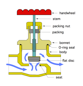
The simplest type of balancing valve is a globe valve, a cross section of which is shown in Figure 3-1.
Flow enters the lower valve chamber, flows upward through the orifice between the seat and the disc, then exits from the upper chamber. The gap between the disc and the seat determines the hydraulic resistance created by the valve. Turning the valve's stem changes the gap between the seat and the disc, which changes the valve's hydraulic resistance. The closer the disc is to the seat, the greater the valve’s hydraulic resistance. The greater the valve’s hydraulic resistance, the greater the pressure drop across the valve at any given flow rate. Although globe valves were traditionally used for balancing they lack several features that modern balancing valves provide.
Manual Balancing Valves With Differential Pressure Ports
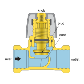
There are several other manually-adjusted valve designs that, in addition to flow rate adjustment, provide a way to measure the flow rate passing through the valve. Many valves in this category have two small ports on the sides of their bodies that can be used to measure the pressure upstream and downstream of the valve’s orifice.
This type of valve is further classified as a variable orifice balancing valve. One of the pressure ports connects to the upstream chamber in the valve, and the other connects to the downstream chamber. The differential pressure is measured across the orifice between these chambers. The knob on the valve controls the position of the valve’s plug relative to the seat, and thus, the size of the orifice (e.g., the “gap” between the plug and the seat). Hence the designation “variable orifice.”
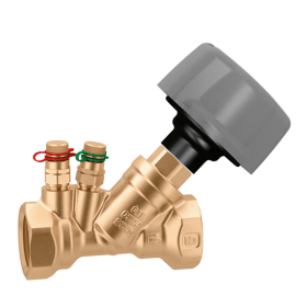
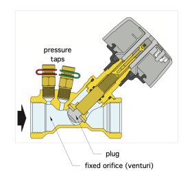
Another type of manually adjusted balancing valve with pressure ports is shown in Figure 3-3a, along with its cross section in Figure 3-3b.
The pressure ports on this valve are located on either side of a fixed conical shape known as a venturi. One port provides the pressure at the inlet of the venturi, and the other port provides the pressure at the exit of the venturi. The differential pressure measured across the venturi can be directly correlated to the flow rate through the venturi. The shaft of the valve moves the valve’s plug toward or away from its seat. This changes the Cv of the valve and correspondingly changes the flow rate passing through it. Because the pressure ports are located along a fixed surface (e.g., the venturi), this type of valve is often called a fixed orifice balancing valve.
Correlating Differential Pressure To Flow Rate
All differential pressure-type balancing valves have a precise relationship between the differential pressure measured at the pressure ports and the corresponding flow rate through the valve. That relationship can be shown as a graph, a table, or automatically determined by specialized instruments called manometers.
Figure 3-4 shows an example of a manometer attached to the pressure ports of a balancing valve using two small-diameter flexible hoses.
Differential pressure-type balancing valves have fine threads on their stem to allow precise adjustment of the plug relative to its seat. The knobs typically show position numbers that match the number of turns the valve stem has opened from its fully closed position.
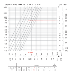
Figure 3-5 is an example of a graph that shows the relationship between the differential pressure ($\Delta P$) read by a manometer and the corresponding flow rate through a specific 3/4" variable orifice balancing valve. To determine the flow rate through the valve, first find the measured differential pressure on the right-side vertical axis. Follow a horizontal line to the left until intersecting a sloping line that corresponds to the valve’s knob position number. Then follow a vertical line to the bottom horizontal axis to read the flow rate.
In this example, the valve's knob is at position #2, and the differential pressure measured between its pressure ports is 3 psi, which infers a flow rate of 3 gpm through the valve. When the balancing requirements for a system are provided as a list of branch flow rates and required pressure drop, it is possible to preset the balancing valve to the required knob position. This reduces subsequent commissioning time.
Balancing Valves With Flow Indication
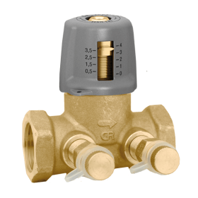
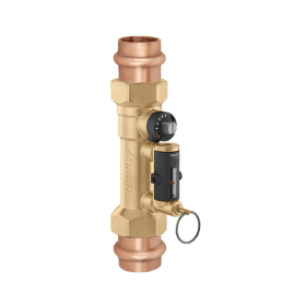
Some manually set balancing valves have integrated flow measurement. Figure 3-6 shows an example.
Pulling the ring on the front of the valve allows a small internal magnet to be moved by the fluid flowing through the valve. This magnet lifts a small steel ball inside a transparent chamber. The position of this small ball indicates the flow rate through the valve. This design eliminates the need to have the flow-indicating element in contact with the system fluid, eliminating the possibility of “clouding” the transparent window on the meter over time.
Sizing Differential Pressure Balancing Valves
Differential pressure-type balancing valves become more subject to inaccuracies due to limitations of typical manometers when operated at differential pressures below 3 KPa (0.435 psi). It follows that balancing valves should be selected so they will operate at pressure drops higher than 3 KPa (0.435 psi). Using this criterion, along with the definition of Cv, leads to the following formula for the maximum Cv of a differential pressure balancing valve.
Formula 3-1:
$$ {C_v}_{BV(Max)}={f \over \sqrt {\Delta P}}=={f\over\sqrt {.435}}=1.52 \times f$$
Where:
${C_v}_{BV(Max)}$ = maximum ${C_v}$ of a balancing valve
$f$= design flow rate through the balancing valve (gpm)
Keep in mind that balancing valves should also be selected to have a minimum valve authority of 0.50, which was discussed in the previous section.
Strengths & Limitations Of Manually Set Balancing Valves
Strengths:
• Simplicity
• No control system required
• Lower cost relative to other types of balancing valves
Limitations:
• More labor required for commissioning
• Cannot compensate for changes in differential pressure caused by zone valves opening and closing
Selection & Installation
Balancing valves should be thought of as “instruments.” They are precisely made to deliver consistent relationships between differential pressure and flow rate. To ensure long-lasting, accurate performance, adhere to the following installation details.
• Always install the valve in the correct flow direction.
• Provide a minimum of 10 pipe diameters of straight pipe upstream of the valve to reduce turbulence.
• Install a high-performance separator to capture fine dirt and magnetic particles within the system.
• Install a strainer upstream of the balancing valve or use an assembly with an integrated strainer.
• Internally wash the system during commissioning with a hydronic detergent.
• Size the valve based on its Cv rating and valve authority rather than its pipe size.
• Be sure that the pressure ports on the valve are easily accessible.

