A wide variety of heat exchangers are used in modern hydronic heating and cooling systems, as well as in some plumbing applications. This section illustrates the most common hardware configurations and describes common applications for these heat exchangers.
INTERNAL vs. EXTERNAL HEAT EXCHANGERS
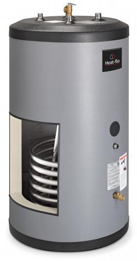
In the context of hydronic systems, internal heat exchangers are typically helical coils made of a metal with high thermal conductivity and suspended within liquid-filled containers such as a thermal storage tank. Figure 2-1 shows an example of an internal coil heat exchanger permanently mounted in the lower portion of a pressure-rated stainless steel tank.
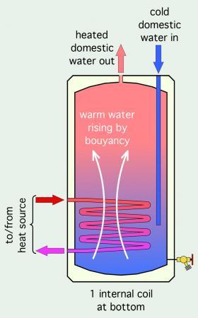
A heated fluid is circulated between the heat source and the inside of the coil heat exchanger. The coil is surrounded by domestic water within the tank’s shell. Heat transfers from the outer coil surface to the domestic water by natural convection.
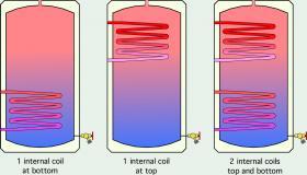
There are several variations of tanks with internal coil heat exchangers.
Tanks with a single lower coil are commonly used for domestic water heating and are referred to as indirect water heaters. Figure 2-3 shows further details for this application.
The single lower coil releases heat into the coolest water, which, due to its density, collects at the bottom of the tank. When hot domestic water is drawn from the top of the tank, cold domestic water enters through a dip tube that carries it to the lower portion of the tank. This helps to preserve beneficial temperature stratification within the tank.
The heat source could be a boiler, heat pump or solar thermal collectors. Hot fluid from the heat source enters the upper coil connection and flows downward, exiting at the lower connection. This flow direction is opposite the direction that water within the tank flows after absorbing heat from the coil. Because the two fluids move in opposite directions, this situation is called “counterflow” heat exchange. Later sections will show why counterflow is important to maximize heat transfer rates.
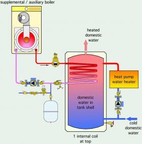
Some systems using heat pumps are designed to supply the heat pump with the coolest water drawn for the lower portion of the tank. The lower the water temperature at which the heat pump operates, the higher its efficiency. Figure 2-4 shows such a system, but with a boiler supplying supplemental (or backup) heat through a coil heat exchanger mounted in the upper portion of the tank.
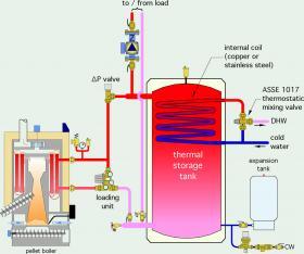
Another possibility is to route domestic water through a coil heat exchanger in the upper portion of the tank, as shown in Figure 2-5.
This requires the coil to be made from a material such as copper or stainless steel that is compatible with domestic water. The coil is surrounded by “system water” that is heated by a heat source and is also used for space heating. The tank in Figure 2-5 can also provide buffering to a zoned distribution system.
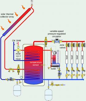
Tanks having upper and lower coil heat exchangers can be used for several applications. One is where the lower coil provides heat input from a solar thermal collector array, while the upper coil provides domestic water heating. The water in the tank shell is heated by a boiler and provides buffering for a highly zoned space-heating system. Figure 2-6 shows an example of such a system.
In some applications, the two internal coil heat exchangers are connected in series to create a single heat exchanger with increased surface area.
DOUBLE WALL COIL HEAT EXCHANGERS
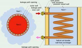
Some mechanical codes require a special type of coil heat exchanger when the application requires transferring heat from an antifreeze solution to potable water. That coil must be “double walled.” There must be a partial air gap between the metal wall that receives heat from the antifreeze solution and the metal wall that transfers heat to potable water. This air gap creates a “leakage path” that would allow a leak in either metal wall to exit the heat exchanger outside of the tank, and thus provide visible evidence of the leak. Figure 2-7 illustrates the concept.
Double wall heat exchangers create lower heat transfer rates compared to single wall coils of equivalent surface area. They also tend to have higher pressure drops at a given flow rate relative to single wall heat exchangers. Opinions vary on their use, as do mechanical code requirements on when and where they must be used.
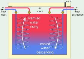
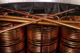
Internal coil heat exchangers, typically made of copper tubing, are also used for heat input and heat extraction from large non-pressurized thermal storage tanks often used in systems supplied by cordwood gasification or pellet-fired boilers. Figure 2-8 shows a typical configuration.
In some systems, one suspended coil is used for heat input while another is used for heat extraction. This is the scenario shown in Figure 2-8. Notice that the flow direction in each coil is opposite the direction in which tank water moves by natural convection. Flow inside the heat input coil is from top to bottom. Flow inside the heat extraction coil is from bottom to top. These counterflow directions improve the rate of heat transfer through each coil.
Piping from each coil passes through the tank’s sidewall above the highest water level. The piping penetrations are sealed to limit evaporation water loss but are typically not rated for submerged operation.
The use of two coil heat exchangers introduces two “thermal penalties” (e.g., undesirable but necessary temperature drops) into the heat transfer process between the heat source and the load. One is the temperature drop between the water entering the heat input coil from the heat source, and the average water temperature in the tank. The other is the temperature drop between the average tank temperature and the outlet temperature from the heat extraction coil. The extent of these temperature drops depends on the surface area of the coil and the convection conditions between the outer surface of each coil and the tank water. In general, it’s desirable to reduce or eliminate any thermal penalty between the heat source and the load. This is especially true for heat sources that require relative low operating temperatures to attain high efficiency.
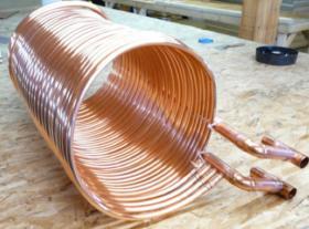
Another approach is to “co-wind” multiple copper tubes into a single helical coil, as shown in Figure 2-10. This provides additional surface area while greatly reducing pressure drop relative to a single coil of the same total surface area. The individual coils are manifolded together at each end of the heat exchanger, allowing for a single supply and return connection.
EXTERNAL HEAT EXCHANGERS
The term “external” heat exchanger refers to any heat exchanger that is not immersed in a fluid inside another component such as a tank. Unless the term “internal” is used to describe the heat exchanger, assume that it is external, and thus just referred to as a heat exchanger.
The most commonly used heat exchangers in hydronic systems can be categorized as follows:
- liquid-to-liquid
- liquid-to-air
The first word in these descriptions refers to the fluid supplying heat. The final word refers to the fluid absorbing heat. For example, in some snowmelting systems, boiler water would be the source liquid, and an antifreeze solution would be the destination liquid. In a cooling application, the first word in the description would be the source of the cooling effect, and the last word would be the destination of the cooling effect.
LIQUID-TO-LIQUID HEAT EXCHANGERS
SHELL AND TUBE HEAT EXCHANGERS
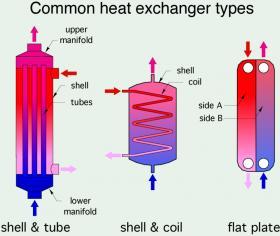
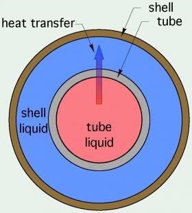
This heat exchanger design stems from the fundamental concept of a pipe that separates two liquids exchanging heat. One liquid surrounds the outer surface of the pipe and the other flows inside the pipe. The fluid surrounding the pipe is contained within another cylindrical vessel called the shell, as shown in Figure 2-12.
In most shell & tube heat exchangers, the cooler fluid passes through the annular space between the outer surface of the tube and the shell. This reduces heat loss from the outer surface of the shell.
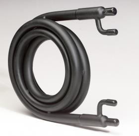
Although it’s possible to create a shell & tube heat exchanger with a single tube, as shown in Figure 2-12, the length of the heat exchanger required to create sufficient heat transfer area for many applications is excessive. In some situations, this length issue is solved by coiling the overall heat exchanger, as shown in Figure 2-13.
This component is called a coaxial tube-in-tube heat exchanger. It is commonly used for water-to-refrigerant heat transfer in heat pumps.
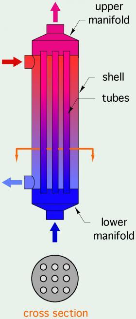
When coiling is not possible, multiple straight tubes are used, as shown in Figure 2-14.
The tubes are welded or brazed to bulkhead plates near each end of the heat exchanger. The two ends of the exchanger serve as manifolds to distribute flow through the multiple tubes. The second liquid passes through the shell of the heat exchanger and around the outer surfaces of all the tubes. These designs can be scaled up to products capable of transferring several millions of Btu/hr.
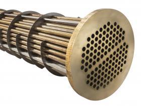
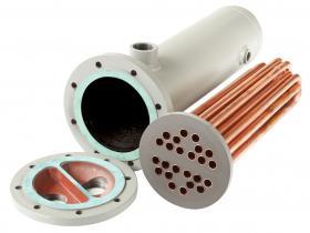
Figure 2-15 shows an example of a large “tube bundle” that would be inserted into an appropriately sized shell. The baffle plates through which the tubes pass increase turbulence within the shell, which increases the convective heat transfer rate.
The tubes and shell are often made of different materials, depending on the chemical nature of the fluids exchanging heat, as well as the temperature and pressure at which the heat exchanger is rated to operate.
Shell and tube heat exchangers are also available with multiple tube passes. One liquid passes through half of the tube bundle in one direction, reverses through U-bends at the other end of the shell, and passes through the remaining tubes, eventually returning to the same end of the heat exchanger. Figure 2-16 shows an example of a 2-pass shell & tube heat exchanger having a welded steel shell and copper tubes. This heat exchanger has a removable cast iron end cap that allows the tube bundle to be removed for cleaning or replacement.
The concept of multiple tube passes can be increased to 3-pass and 4-pass designs. Most shell & tube heat exchangers also have internal baffle plates that increase turbulence on the shell side for improved convective heat transfer.
Shell & tube heat exchangers are commonly used for industrial applications, often at high temperatures and pressures. Many of these heat exchangers can be opened for servicing or replacement of the tube bundle. They are seldom used in smaller residential and light commercial hydronic systems. Their design requires significantly more metal volume relative to other heat exchanger designs of comparable capacity. The physical size of a shell & tube heat exchanger required to provide for a given internal area is also larger than that of other heat exchanger designs. Shell & tube heat exchangers also tend to have greater external surface area relative to other designs and thus experience higher parasitic heat loss for a given set of operating conditions. They are also more prone to fouling deposits due to lower internal flow velocities in the shell.
SHELL AND COIL HEAT EXCHANGERS
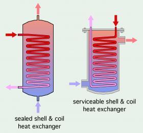
A shell and coil heat exchanger is made by enclosing a helically shaped coil of tubing within a metal or composite shell. One fluid passes through the coil while the other passes through the shell and over the outer surface of the coil. Figure 2-17 shows two variations of shell & coil heat exchangers.
The geometry of the shell varies. Some shells are designed for vertical installation, with connection at the top and bottom. Others are designed for installation in a variety of orientations, with side connections on the shell and coil connections at one end. Some shell & coil heat exchangers have the coil permanently welded or brazed to the shell. Others allow the coil to be removed by unbolting a sealed end plate at one end of the shell.
Shell & coil heat exchangers have been used for heat transfer between two liquids as well as between a liquid and a refrigerant. In the latter case, the refrigerant typically passes through a welded steel shell, while the liquid passes through a copper coil. In some systems, the volume of the shell also serves as a liquid accumulator within a refrigeration circuit.
Shell & coil heat exchangers are not commonly used for liquid-to-liquid heat transfer in hydronic systems. One limitation is the amount of coil surface area versus the overall size of the heat exchanger. Another is the higher fluid volume in the shell, which increases thermal mass and decreases the heat exchanger’s response time to temperature changes relative to that of other heat exchanger designs.
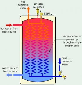
One application where the increased thermal mass of a shell & coil design is desirable is when the heat exchanger also serves as a thermal storage device. A “reverse” indirect water heater, as shown in Figure 2-18, is a good example.
One can think of this reverse indirect water heater as a high surface area shell & coil heat exchanger with added thermal mass and insulation. Domestic water is fully heated on a single upward pass through multiple copper coils that are manifolded together at the top and bottom of the tank. Hot water from a boiler or other heat source passes through the steel shell of the tank, transferring heat to the copper coils.
FLAT PLATE HEAT EXCHANGERS
One of the most contemporary devices for fluid-to-fluid heat exchange is called a flat plate heat exchanger. This type of heat exchanger is now used in many types of hydronic heating and cooling systems, as well as for the evaporator and condenser in some refrigeration systems.
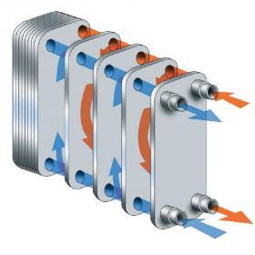
Fundamentally, a flat plate heat exchanger is created by stacking several pre-formed metal plates and sealing the perimeter of those plates together. The plates are shaped to create narrow flow channels between them. One fluid passes from one end of the heat exchanger to the other through the odd-numbered channels (1, 3, 5, 6, etc.). The other fluid passes from one end of the heat exchanger to the other through the even-numbered channels (2, 4, 6, 8, etc.). This concept is illustrated in Figure 2-19.
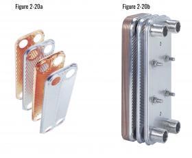
Figure 2-20 shows examples of the preformed stainless steel plates and a partially disassembled flat plate heat exchanger. The placement of the holes within the plates creates four internal manifold cavities. These cavities ensure even distribution of both fluids into their respective channels. The cavities transition to piping connections at one end of the heat exchanger, as seen in Figure 2-20b.
The patterned plates are designed to encourage turbulent flow, and thus high convection coefficients. Some manufacturers offer different plate patterns to create internal flows that are well-matched to specific fluid properties and a desired flow rate and pressure drop characteristics.
For a given set of entering temperatures, flow rates and fluid characteristics, the heat transfer capacity of a flat plate heat exchanger depends primarily on the size and number of plates used.
Flat plate heat exchangers can be further classified as:
- Brazed plate heat exchangers
- Plate and frame heat exchanger
BRAZED PLATE HEAT EXCHANGERS
As the name implies, all the plates on a brazed plate heat exchanger are brazed together at their perimeter, as well as where internal surfaces come in contact. The brazing is typically done with a copper alloy. This metallurgically seals the flow channels and creates two separate pressure-rated compartments within the heat exchanger. Once it is brazed, the heat exchanger cannot be modified or opened.
Most manufacturers have standardized plates sizes for their brazed plate heat exchangers. Typical plate dimensions are 3 x 8 inches, 5 x 12 inches and 10 x 20 inches. For a given plate size, the heat transfer capacity is increased by adding plates to the “stack” that becomes the overall heat exchanger. For example, a 5 x 12 x 40 flat plate heat exchanger is built using 40 plates of nominal dimension 5 inches by 12 inches. One unique plate forms the back of the heat exchanger (e.g., it has no holes through it). Another unique plate forms the front of the heat exchanger and transitions to the four piping connections.
Brazed plate heat exchangers are typically used in small- to medium-scale hydronic systems, where heat transfer rates up to several hundred thousand Btu/hr are required. A small brazed plate heat exchanger might have 10 plates measuring a nominal 3 inches by 8 inches. A large brazed plate exchanger might have 100 plates measuring a nominal 10 inches by 20 inches.
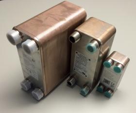
Figure 2-21 shows three examples of brazed plate heat exchangers: A small 3 x 8-inch x 10 plate, a 5 x 12-inch x 30 plate, and a 5 x12-inch x 100 plate. The largest heat exchanger has 1-1/4-inch MPT connections. The medium-sized exchanger has 1 inch MPT connections. The small heat exchanger has 3/4-inch FPT connections.
Most of the brazed plate heat exchangers used in hydronic heating and cooling systems are constructed of 316 stainless steel. This allows them to operate with potable water having some chloride content, as well as a range of system fluids, including most antifreeze solutions. Some manufacturers also offer heat exchangers made of less-expensive 304 stainless steel for applications using fluids with low chloride content. Brazed plate heat exchangers typically have pressure and temperature ratings well above those needed in hydronic systems.
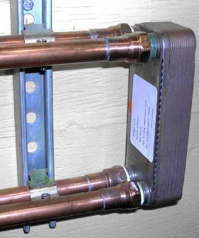
Small brazed plate heat exchangers are relatively light. A 3 x 8-inch heat exchanger can be supported by the 4 pipes connected to it. However, those pipes should be supported within a few inches of the heat exchanger, as shown in Figure 2-22.
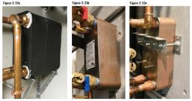
Heat exchangers with 5-inch x 12-inch (or larger) plates should be supported by some type of bracket to reduce stress on the connected piping. Figure 2-23a shows an example of a fabricated bracket supporting an insulated 5 x 12-inch x 100 plate heat exchanger. Figure 2-23b shows a 5 x 12-inch x 40 plate heat exchanger supported on a small steel angle bracket screwed to a plywood wall. Some brazed plate heat exchangers are supplied with threaded studs that can be fastened to a metal bracket, as shown in Figure 2-23c.
Brazed plate heat exchangers are also available with double wall construction for situations where codes require them. These units provide a leakage path between adjacent plates that would route any leaked fluid outside the heat exchanger.
PLATE AND FRAME HEAT EXCHANGERS
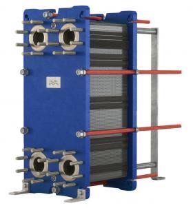
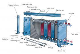
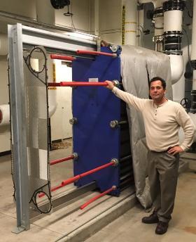
Plate and frame heat exchangers could be considered the “big brother” to brazed plate heat exchangers. They use the same concept of a stack of preformed plates to separate the two fluids in alternating channels. However, instead of brazing, plate & frame heat exchangers use gaskets to seal the fluid channels. The stack of plates is assembled on a frame between two thick steel pressure plates. When the required number of plates have been loaded onto the frame, several threaded steel rods are used to pull the pressure plates together and compress the stack into a pressure-tight assembly. The plate stack, pressure plates and tension rods can be seen on the heat exchanger in Figure 2-24.
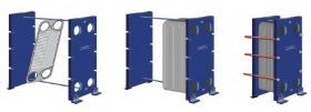
Large plate and frame heat exchangers are typically assembled close to, or exactly at, their final position within a mechanical room. Each plate is “hung” from an upper rail and slid into initial position to form the plate stack. The threaded steel draw rods are carefully tensioned using torque wrenches to ensure even compression of the stack. This assembly concept is shown in Figure 2-25.
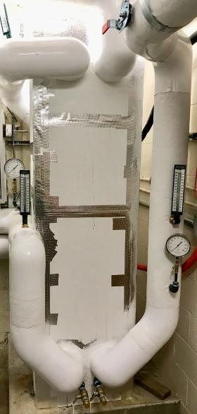
Large plate & frame heat exchangers are heavy. They are usually anchored to concrete pads within mechanical rooms, as seen in Figure 2-27.
The large plate & frame heat exchanger in Figure 2-27 has been fully insulated to reduce heat loss into he mechanical room. The welded steel piping connected to this heat exchanger has also been insulated and jacketed. Note the installation of thermometers near all four ports of the heat exchanger. Drain valves that tee into the two lower pipes can also be seen.
The frames used for plate & frame heat exchangers are usually large enough to accommodate more plates than the initial design requires. More plates can be added if the capacity of the original system is increased. Figure 2-28 shows an example of the additional “rack space” available on a large plate & frame heat exchanger.
The extended ends of the tension rods are typically covered with plastic tubes for safety.
Although plate & frame heat exchangers can be disassembled for cleaning or plate replacement, this is a laborious task. It is always better to use proper dirt separation details in the system to prevent debris from entering the heat exchanger.
As is true with all heat exchangers, it is very important to pipe flat plate heat exchangers so that the two liquids pass through it in opposite directions (e.g., counterflow). In most cases, each fluid passage through a flat plate heat exchanger leads back to two connections, one above the other, at one end of the heat exchanger, as shown in Figure 2-19.
Flat plate heat exchangers have several benefits relative to other heat exchanger designs. They include:
- A very high ratio of surface area to internal volume. This allows flat plate heat exchangers to be significantly smaller than a shell & tube or shell & coil heat exchanger of equivalent heat transfer capacity. It also allows for a rapid response to temperature changes in either fluid. Small brazed plate heat exchangers can achieve steady state conditions within a few seconds after two stable fluid streams (e.g., constant flow rate and stable entering temperature) begin flowing through them.
- The metal plates can be thinner than the tubing used in other types of heat exchangers. This reduces the thermal resistance between the two fluids. Later Sections will show how to account for plate thickness when determining heat exchanger performance.
- The patterns used on the plates allow for relatively high turbulence, which increases convective heat transfer and potentially reduces the required internal surface area of the heat exchanger. Higher turbulence also decreases the potential for dirt or other fouling materials to stick to the plates.
FAN-FORCED LIQUID-TO-AIR HEAT EXCHANGERS
One could think of any hydronic heat emitter, be it a cast iron radiator, heated floor slab or a finned-tube baseboard, as a liquid-to-air heat exchanger. All of these heat emitters — to some degree — rely on natural convection heat transfer to move heat from a stream of water to room air. These heat emitters have been discussed in several past issues of idronics. In this issue, the discussion focuses on devices that use a fan or blower to create airflow through the heat exchanger.
There are many situations in which the heat in a stream of water needs to be transferred directly to air within an interior space. Likewise, nearly all hydronic chilled-water cooling systems need a means of extracting heat and moisture from inside air. Many products have been developed for these applications using forced convection heat transfer on both the water and air side of the heat exchanger. They can be categorized as follows:
- Fan-coils
- Air handlers
FAN-COILS
A fan-coil is fundamentally a combination of a water-to-air heat exchanger, known as a “coil,” with a fan or blower that creates forced convection on the air side of that coil. In general, fan-coils are designed to heat or cool individual spaces within a building. Multiple fans coils can be used to create heating and cooling zones within a building.
All fan-coils can be used for heating when supplied with heated water. Only fan-coils equipped with internal condensate drip pans can be used for cooling when supplied with chilled water.
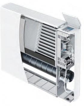
Figure 2-29 shows the internal components of a modern “console” fan coil. The coil consists of copper tubing routed through closely spaced aluminum fins. It’s visible near the top of the unit. A tangential blower wheel located below the coil and rotated by a high-efficiency, electronically commutated motor draws room air into the cabinet from a few inches above floor level. This air is blown across the coil and discharged through the upper grill.
Beyond this basic heat transfer and air movement functionality are controls that vary from one manufacturer to another. In modern fan-coils, these controls can regulate blower speed and operate the fan-coil based on specific setpoint temperatures for heating and cooling and time of day.
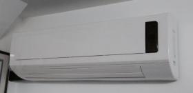
Another form factor that is currently used for fan-coils is called a “high wall cassette,” an example of which is shown in Figure 2-30.
High wall cassettes are equipped with condensate drain pans and can be used for hydronic heating or cooling. They draw room air into the top of the cabinet and discharge air through a lower opening equipped with oscillating vanes to dispense air in different directions. As shown, the unit in Figure 2-30 is off. The air discharge slot at the bottom of the unit is covered by a motorized damper.
High wall cassettes are typically turned on and off using a handheld remote. The speed of the fan can be adjusted from the remote or automatically for specific modes of operation. For example, a low fan speed is used when the unit is set for dehumidification mode, allowing the coil to extract more moisture from the air stream.
Some fan-coils are available for recessed mounting in wall cavities. Some have air filters, while others do not. They are available in a wide range of heating and cooling capacities depending on size and source water temperature.
AIR HANDLERS
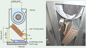
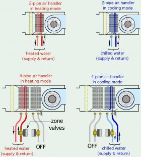
Air handlers, as well as some fan-coils, are available in either “2-pipe” or “4-pipe” configurations. These configurations are shown in Figure 2-32.
A “2-pipe” air handler has a single coil heat exchanger. That coil can provide heating or cooling depending on the temperature of the water stream supplied to it. Two-pipe air handlers are supplied from a distribution system that has a single supply main and single return main. This distribution system can operate with heated water or chilled water, but not both at the same time. Two-pipe air handlers are used in applications where the entire distribution system operates in a single mode (e.g., heating mode or cooling mode) at any given time.
Four-pipe air handlers have two water-to-air coil heat exchangers. One coil is piped to a distribution system for chilled water. The other coil is piped to a separate distribution system for heated water. Any 4-pipe air handler connected to these two independent distribution systems can operate in either heating mode or cooling mode. The operating mode is usually determined by a thermostat in the space served by the air handler. When heating is needed, a zone valve opens to allow hot water to flow through the heating coil in the air handler. The blower is also turned on. When the thermostat calls for cooling, a separate zone valve opens to allow chilled water to flow through the chilled water coil, along with blower operation. Four-pipe distribution systems connected to multiple 4-pipe air handlers allow for simultaneous heating and cooling in different areas of a building.
Notice that the direction of water flow through the coils in both 2-pipe and 4-pipe air handlers is opposite the direction of airflow. This is important in achieving counterflow heat exchange, and thus the highest possible rate of heat transfer for a given set of operating temperatures and flow rates.
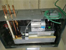
Figure 2-33 shows a partially installed 4-pipe air handler that’s suspended from a concrete slab and above what will eventually be the room’s ceiling. This is a common air handler configuration for buildings such as hotels using a 4-pipe distribution system.
The four copper tubes seen at the left of the air handler cabinet provide supply and return water flow to the heating and cooling coils. They are fitted with adapters to connect to PEX distribution tubing. Each coil circuit is controlled by a Z-one™ zone valve within the cabinet. Each coil circuit is also equipped with a QuickSetter™ flow-balancing valve within the cabinet. The condensate drip pan, which is connected to a 3/4” PVC drainpipe, is visible at the base of the unit.
One fundamental distinction between fan coils and air handlers is that the latter is typically designed to connect to a ducted air delivery system. This allows the air stream created by the blower to be simultaneously delivered to several locations in a building.
Another distinction is that most air handlers are intended to be installed in non-occupied locations such as mechanical rooms, interior soffits, basements or attics. They are not designed with aesthetic details to make them acceptable in finished occupied spaces.
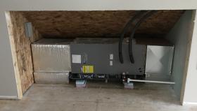
Figure 2-34 shows a small, horizontally oriented, 2-pipe air handler connected to a ducted forced-air delivery system.
This unit is mounted in an accessible area within a conditioned attic. A removable panel will eventually be installed to conceal the unit. The coil in this air handler is supplied by insulated piping carrying chilled water for cooling. Because it is installed above a finished space, this air handler is mounted over a secondary drain pan that would capture any condensate that might leak from the unit’s primary condensate drip pan. The condensate formed on the coil during cooling mode is carried to a drain through the small PVC pipe seen at the lower right of the unit.
Small air handlers that are commonly used in homes or small commercial buildings may have heating and cooling capacities ranging from about 12,000 Btu/hr (1 ton) to about 60,000 Btu/hr (5 tons). However, many air handlers are available with heating and cooling capacities much higher than those of fan-coils.
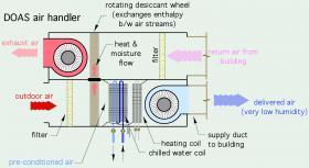
Large air handlers can have heating and cooling capacities of several million Btu/hr. These large units are typically custom-built for specific applications. They typically have separate water-to-air coils for heating and cooling, separate blowers for the supply and return air streams, energy recovery devices, and more elaborate air-filtering systems compared to small air handlers. Figure 2-35 illustrates some of these internal details.
The thermal performance of fan-coils and air handlers will be discussed in Section 4.
GREYWATER HEAT RECOVERY HEAT EXCHANGERS
Heat exchangers are also used in plumbing applications. One example is recovering heat from domestic hot water that has passed through a fixture such as a lavatory or shower. This water is commonly referred to as “greywater.”
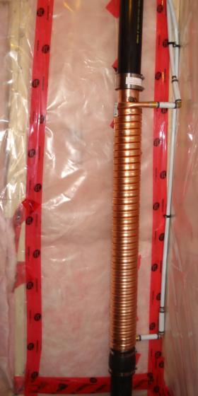
Much of the heat in domestic hot water remains in that water as it goes down the drain. In most buildings, this heat is simply carried into the sewer. However, it is possible to recover up to 40% of this otherwise wasted heat using a greywater heat exchanger, an example of which is shown in Figure 2-36.
Greywater heat exchangers are simple devices. They are fitted into a vertical section of greywater drainage piping. That pipe should be configured to carry drainage water from lavatories, showers, tubs and clothes washers, but not drainage from garbage disposals, toilets or bidets.
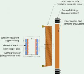
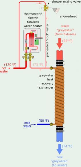
These heat exchangers consist of an inner copper pipe that’s wrapped with one or more coils of tightly fitting, partially flattened copper tubing that is bonded to the outer surface of the inner pipe. The construction of a typical greywater heat exchangeris shown in Figure 2-37. A typical installation configuration is shown in Figure 2-38.
Greywater heat exchangers leverage the simultaneous flows of cold water and hot water to fixtures such as lavatories and showers. As hot domestic water is being used, cold domestic water enters the bottom connection of the heat exchanger and passes upward in a counterflow direction to the greywater. Heat from the greywater transfers through the copper tube walls and preheats cold domestic water. The two streams of water are always separated by two copper tube walls. A potential leak in either the inner pipe or outer coil would not cause contamination of domestic water.
Greywater heat exchangers leverage the simultaneous flows of cold water and hot water to fixtures such as lavatories and showers. As hot domestic water is being used, cold domestic water enters the bottom connection of the heat exchanger and passes upward in a counterflow direction to the greywater. Heat from the greywater transfers through the copper tube walls and preheats cold domestic water. The two streams of water are always separated by two copper tube walls. A potential leak in either the inner pipe or outer coil would not cause contamination of domestic water.
In Figure 2-37, some of the preheated water leaving the greywater heat exchanger is piped directly to the “cold” water port of the shower valve. This reduces the required flow of fully heated domestic hot water to the shower valve.
Under typical operating conditions, the entering cold domestic water will be warmed 20º to 25ºF before it exits the heat exchanger. Thus, water entering the building at 50ºF, would be preheated to a temperature of 70º to 75ºF before entering the water heater. This reduces the water heating load by 29% to 36%, assuming a final desired delivery temperature of 120ºF. This is a significant contribution for a simple, unpowered and relatively inexpensive device.
Greywater heat exchangers should only be installed in vertical drainage pipes. They rely on the “film effect” of greywater passing through a vertical drainage pipe. Most of this water clings to the pipe wall, rather than falling through the air space inside the pipe. This is ideal from the standpoint of extracting heat from the inner copper pipe.

