Two fundamental concepts apply to all situations involving heat transfer:
- Heat always moves from a material at some temperature to another material at a lower temperature.
- The rate of heat transfer depends on the temperature difference between the two materials. The greater this difference, the higher the rate of heat transfer.
To understand the processes at work in different types of heat exchangers, it’s essential to understand the three modes of heat transfer. A well-established scientific principal is that all heat movement occurs by one or more of the following modes:
- Conduction
- Convection
- Thermal radiation
CONDUCTION
Conduction heat transfer takes place within solid materials. It’s the result of atomic vibrations within those materials. The atoms in all materials having temperatures above absolute zero (-458ºF) vibrate to some extent. The higher the material’s temperature, the more vigorous the atomic vibrations.
When heat is added to a solid material, the atomic vibrations become more energetic. These vibrations spread out across trillions of atoms that are bonded together, moving towards material at a lower temperature.
The physical property that determines how well a material transfers heat by conduction is called its thermal conductivity. The higher a material’s thermal conductivity value, the faster heat can pass through it, with all other conditions being equal. The thermal conductivity of a material is usually determined by testing. The thermal conductivity of many materials is listed in references such as the ASHRAE Handbook of Fundamentals.
Heat moving through cast iron that separates the combustion gases from the water inside a boiler is an example of conduction heat transfer. Heat passing from tubing embedded in a concrete slab to the surface of that slab is another example. Heat passing from a person’s hand to the cold metal handle of a snow shovel is another.
The rate of heat transfer by conduction is directly proportional to both the temperature difference across the material and its thermal conductivity. It is inversely proportional to the thickness of a material. Thus, if one were to double the thickness of a material while maintaining the same temperature difference between its sides, the rate of heat transfer through the material would be cut in half.
Materials such as copper, aluminum and steel have relatively high thermal conductivities. Copper and aluminum in particular are frequently used in applications where high rates of conduction heat transfer are necessary.
The rate of conduction heat transfer depends on the thermal conductivity of the material, its thickness, the area across which heat is passing, and the temperature difference across it. The relationship between these quantities is given in Formula 3-1.
Formula 3-1:
$$ q = A \biggl({k \over \Delta x} \biggr) (\Delta T) $$
Where:
$q$ = rate of heat transfer through the material (Btu/hr)
$k$ = thermal conductivity of the material (Btu/°F•hr•ft)
$\Delta x$ = thickness of material in the direction of heat flow (ft)
$\Delta T$ = temperature difference across the material (°F)
$A$ = area heat flows across (ft2)
The mathematical term (${k \over \Delta x}$) in Formula 3-1 is sometimes called a heat transfer coefficient and is represented by the symbol ($U$). The reciprocal of the heat transfer coefficient $U$ (e.g., ${1 \over U}$) is called “thermal resistance,” and is represented by ($R$).
Formula 3-1 can therefore be modified into Formula 3-2.
Formula 3-2:
$$ q = {A \over R} (\Delta T) $$
Where:
$q$ = rate of heat transfer through the material (Btu/hr)
$R$ = thermal resistance (or “R-value”) of a material (ºF•hr•ft2/Btu)
$\Delta T$ = temperature difference across the material (°F)
$A$ = area heat flows across (ft2)
The $R$-value of a material can be determined based on its thermal conductivity ($k$), and its thickness (∆X). The relationship is given as Formula 3-3.
Formula 3-3:
$$ R = {\Delta x \over k} $$
Where:
$k$ = thermal conductivity of the material (Btu/°F•hr•ft)
$\Delta x$ = thickness of the material in the direction of heat flow (ft)
The $U$-values and $R$-values of materials used to build heat exchangers critically important. In general, materials and thicknesses that provide high $U$-value and thus low $R$-value, allow for higher thermal performance when heat needs to pass through a solid material separating the two fluids.
CONVECTION
Convection heat transfer occurs as the result of fluid movement. The fluid can be a liquid or a gas.
When heated, fluids expand. This lowers their density relative to surrounding cooler fluid. Lowered density increases buoyancy, which causes the warmer fluid to rise. Examples of the latter include warm air rising toward the ceiling in a room and heated water rising to the upper portion of tank-type water heater. Both processes occur without circulators or blowers. As such, they are examples of “natural” convection.
Convection heat transfer is also responsible for moving heat between a fluid and a solid.
For example, consider water at 100ºF flowing along a solid surface that has a temperature of 120ºF. The cooler water molecules contacting the warmer surface absorb heat from that surface. These molecules are churned about as the water moves along. Molecules that have absorbed heat from the surface are constantly being swept away from that surface into the bulk of the water stream and replaced by cooler molecules. One can envision this form of convective heat transfer as heat being “scrubbed off” the surface by the flowing water.
The speed of the fluid moving over the surface greatly affects the rate of convective heat transfer.
Most people have experienced “wind chill” as cold outside air blows past them. They feel “colder” compared to how they would feel if standing in still air at the same temperature. The faster the air blows past them, the greater the rate of convective heat transfer between their skin or clothing surfaces and the air stream. Although the person may feel as if the moving air is colder, it isn’t. Instead, they’re experiencing an increased rate of heat loss due to enhanced convective heat transfer. Achieving the same cooling sensation from calm air would require a much lower air temperature.
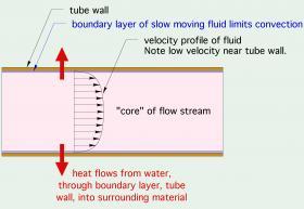
Convective heat transfer increases with increasing fluid speed. This happens because a layer of fluid called the “boundary layer,” which clings to surfaces, gets thinner as the fluid’s velocity increases (see Figure 3-2).
The thinner the boundary layer, the lower the thermal resistance between the core of the fluid stream and the surface. Less thermal resistance allows for higher rates of heat transfer between the fluid molecules in the core of the stream and the tubing wall.
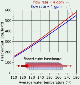
The relationship between convective heat transfer and fluid speed across a surface can be seen in many hydronic systems. For example, the faster water flows through a finned-tube baseboard, the higher it’s heat output, assuming all other conditions remain the same. This effect is evident in the heat output rating data listed by manufacturers of finned-tube baseboard. Figure 3-3 shows a plot of this data for a typical residential finned-tube baseboard.
At any given water temperature, the heat output occurring at a flow rate of 4 gallons per minute (gpm) is slightly higher than at a flow rate of 1 gpm. This increase is due to a thinner boundary layer between the bulk of the fluid stream and the inner tube wall of the finned-tube element.
In general, the faster one or both fluids flow through any type of heat exchanger, the higher the rate of heat transfer between those fluids. From the standpoint of heat transfer only, there is no such thing as the water moving “too fast” through any type of heat exchanger. However, other considerations, such as pumping power, noise or long-term erosion of materials, impose practical limits on flow velocity through heat exchangers.
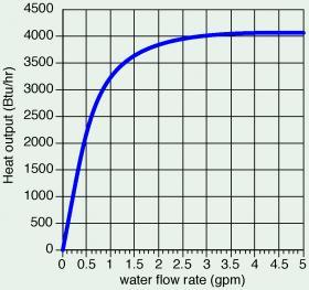
One example of increasing convective heat transfer with increasing flow rate can be found in heat output ratings for the liquid-to-air heat exchanger in a small fan-coil unit. Figure 3-4 shows how heat output increases with increasing water flow rate through the coil heat exchanger, while the inlet water temperature, the incoming air temperature and the airflow rate all remain constant.
The heat output rate increases rapidly at low flow rates. It continues to increase as flow rate increases, but the rate of increase is much slower at higher flows. This demonstrates that there are practical limits on how much the heat output of a hydronic heat emitter can be increased based on higher flow rates.
NATURAL vs. FORCED CONVECTION
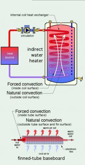
When fluid motion is caused by a circulator, a blower, a fan or any other powered device, the convective heat transfer is called “forced convection.” When the fluid motion is strictly the result of buoyancy differences within the fluid, the convective heat transfer is called “natural convection.”
There are many types of heat exchangers that operate with natural convection on one surface and forced convection on the other side of that surface. One example is at the external surface of an internal coil heat exchanger within an indirect water heater. Another is the external surface of finned-tube baseboard, as shown in Figure 3-5.
Natural convection is typically a much “weaker” form of heat transfer compared to forced convection. This is the result of much slower fluid motion created by buoyancy differences in the fluid versus faster fluid motion created by a circulator or blower. Slower fluid motion increases boundary layer thickness, which creates greater resistance to heat transfer between the bulk of the fluid and the surface.
The difference between forced convection and natural convection explains why a small wall-mounted fan-coil that’s only 18 inches wide can provide the equivalent heat output of 10+ feet of finned-tube baseboard when both are operating at the same water supply temperature and flow rate. The rate of heat transfer from the finned-tube element in the baseboard is limited by natural convection heat transfer between its outer surfaces and the surrounding air.
The rate of convective heat transfer can be estimated using Formula 3-4:
$$ q = hA( \Delta T) $$Where:
$q$ = rate of heat transfer by convection (Btu/hr)
$h$ = convection coefficient (Btu/hr•ft2•ºF)
$A$ = area over which fluid contacts a surface with which it exchanges heat (ft2)
$\Delta T$ = temperature difference between bulk fluid stream and surface (ºF)
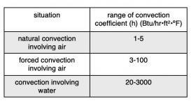
Although Formula 3-4 is relatively simple, determining the value of the convection coefficient (h) is often a complex process. The value of (h) varies widely depending on the “geometry” of the surface relative to the fluid, the speed of the fluid and the physical properties of the fluid (e.g., thermal conductivity, specific heat, density and viscosity). In many cases, the value of (h) needs to be determined experimentally. Heat transfer textbooks sometimes list values of (h) or methods for determining (h) for very specific and simplified situations. The table in Figure 3-6 shows how wide the range of (h) values can be for specific situations.
THERMAL RADIATION
Heat transfer by thermal radiation is less intuitive compared to conduction and convection. To many, the word “radiation” denotes an undesirable or harmful effect associated with nuclear radiation. However thermal radiation and nuclear radiation are very different. Human skin as well as clothing surfaces emit thermal radiation to any surrounding surface that’s at a lower temperature. A lightly clothed human body releases over half of its metabolic heat production as thermal radiation.
It’s helpful to think of thermal radiation as light. More specifically infrared light. Human eyes cannot see infrared light. However, just like visible light, infrared light (a.k.a. thermal radiation) travels outward from its source in straight lines at the speed of light (186,000 miles per second). Although it cannot “bend” around corners, thermal radiation can be reflected by some surfaces. It also travels equally well in any direction, from some surface that emits it to another surface that absorbs it. For example, just as a ceiling-mounted lighting fixture can shine visible light onto objects below, thermal radiation can shine down from a heated ceiling and be absorbed by objects below.
The instant thermal radiation is absorbed by the surface of an object, it becomes heat that warms that object.
Unlike conduction or convection, thermal radiation needs no material (e.g., a fluid or solid) to transfer heat from one location to another. Thermal radiation cannot pass through a solid (as radiation). It can, to differing extents, pass through gases with minimal warming effect on those gases. Intense sunlight passing through very cold air in the upper layers of the earth’s atmosphere is an example of the latter.
Consider a person kneeling a few feet away from a campfire on a cold winter day. If pointed toward the fire, their face likely feels warm, even though the air surrounding them is cold. This sensation is the result of thermal radiation emitted by the fire traveling through the cold air and being absorbed by their exposed skin. The air between the fire and the person absorbs very little of the energy being transferred from the flames to the person’s face. Likewise, thermal radiation emitted from the warm surface of a heat emitter such as a panel radiator can pass through the air in a room without first heating that air. When the thermal radiation strikes another surface in the room, most of it is absorbed. At that instant, the energy carried by the thermal radiation becomes heat.
Every surface continually emits thermal radiation to any cooler surface within sight of it. The surface of a heat emitter that is warmer than our skin or clothing surfaces transfers heat to us by thermal radiation. Likewise, our skin and clothing continually give off thermal radiation to any surrounding surfaces at lower temperatures. A lightly clothed person standing next to a large cold window surface emits significant thermal radiation to that cold surface. This eventually leads to discomfort, even when the air temperature surrounding the person is in the normal comfort range of 68-72ºF.
When thermal radiation strikes an opaque surface, part of it is absorbed as heat and part is reflected away from the surface. The percentage of incoming radiation that is absorbed or reflected is determined by the optical characteristics of the surface and the wavelength of the radiation. Most interior building surfaces absorb the majority of thermal radiation that strikes them. The small percentage that is reflected typically strikes another surface within the room where most of it will be absorbed, and so on. Very little, if any, thermal radiation emitted by warm surfaces in a room escapes from the room.
The rate at which thermal radiation transfers heat between two surfaces depends upon their temperatures, an optical property of each surface called emissivity, as well as the angle and distance between the surfaces.
The rate of heat exchange by thermal radiation between two parallel flat surfaces having the same area can be estimated using Formula 3-5: $$ q = {sAF_{12} (T_1^4-T_2^4) \over \left[ {1 \over e_1} + {1 \over e_2} -1 \right] } $$
Where:
$q$ = rate of heat transfer from hotter to cooler surface by thermal radiation (Btu/hr)
$s$ = Stefan Boltzmann constant = 0.1714x10⁻⁸ Btu/hr•ft2•ºR4
$F_{12}$ = shape factor between the two surfaces (unitless)
$A$ = area of either surface (ft2)
$T_1$ = absolute temperature of the hotter surface (ºR)
$T_2$ = absolute temperature of the cooler surface (ºR)
$e_1$ = emissivity of the hotter surface (unitless)
$e_2$ = emissivity of the cooler surface (unitless)
This formula is more complex that those used for estimating conduction and convection heat transfer.
The value of the “shape factor” ($F_{12}$) is a number between 0 and 1.0. It’s determined based on the relative angle and distance between the two surfaces exchanging radiant heat. Heat transfer textbooks give specific methods for finding values of the shape factor ($F_{12}$) for different surfaces and orientations. For two parallel planes having infinite width and depth, the value of the shape factor ($F_{12}$) is 1.0.
Factors $e_1$ and $e_2$ are the emissivities of surfaces 1 and 2. Emissivity is a surface property determined experimentally based on how well the surface emits thermal radiation. It must be a number between 0 and 1. A high value indicates that the surface is a good emitter, and vice versa. Emissivity values for various surfaces can be found in references such as heat transfer handbooks. Interestingly, the emissivity of a surface is not necessarily correlated with its color. A rough metal surface coated with white enamel paint has an emissivity of 0.91, and a flat black painted surface has an emissivity of 0.97. Freshly fallen snow can have an emissivity over 0.90. The emissivity of a polished copper surface is 0.023, while a heavily oxidized copper surface has an emissivity of 0.78. Most highly polished metal surfaces have low emissivities, and thus would not be good choices for the surface of a hydronic heat emitter that’s expected to radiate heat into a room.
It’s also important to understand that the temperatures (T1) and (T2) in Formula 3-5 must be absolute temperatures. Temperatures in ºF can be converted to absolute temperatures in degrees Rankine (ºR) by adding 458 degrees. Thus, 32ºF becomes 32 + 458 = 490ºR.
The mathematical result of the calculation (T14-T24) changes much more than the simple ΔT term used in the formulas for conduction and convection. For example, consider two surfaces exchanging radiant heat with temperatures of 100ºF and 80ºF. These temperatures would convert to 558ºR and 538ºR. The difference between these temperatures would be only 20ºR, the same as the difference between 100ºF and 80ºF. However, when these Rankine temperatures are used in Formula 3-5 the resulting number for the term (T14-T24) is 131,700,000ºR4.
Due to mathematical complexities, as well as variability or uncertainty in properties such as surface emissivities, theoretical calculations of radiant heat transfer are often limited to relatively simple situations.


