This section discusses how the refrigeration cycle is used by HPWHs and the potential efficiency advantages of proper implementation.
Refrigeration Cycle
Nearly all current-generation heat pump water heaters operate on a basic “vapor/compression” refrigeration cycle. During this cycle, a chemical compound called the refrigerant circulates around a closed piping loop passing through all major components of the heat pump. These major components are named based on how they affect the refrigerant passing through them. They are as follows:
• Evaporator
• Compressor
• Condenser
• Thermal expansion valve (TXV)
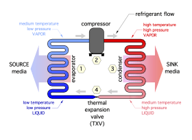
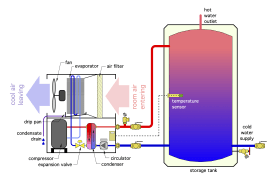
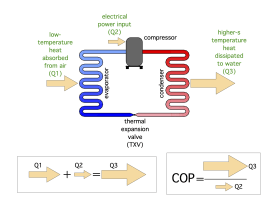
The basic arrangement of these components to form a complete refrigeration circuit are shown in Figure 2-1. To describe how this cycle works, a quantity of refrigerant will be followed through the complete cycle.
The cycle begins at station (1) as cold liquid refrigerant within the evaporator. At this point, the refrigerant is colder than the air surrounding the evaporator. That air is generically referred to as the “source media,” because it is the source of the low-temperature heat. Because of the temperature difference between them, heat moves from the air into the lower-temperature refrigerant. As the refrigerant absorbs this heat, it changes from a liquid to a vapor (e.g., it evaporates). The vaporized refrigerant continues to absorb heat until it is slightly warmer than the temperature at which it evaporates.
The vaporized refrigerant flows on to the compressor, where its temperature and pressure are increased. The electrical energy used to operate the compressor is also converted to heat and added to the refrigerant. The temperature of the refrigerant gas leaving the compressor is usually in the range of 120º to 170ºF, depending on the operating conditions.
The hot refrigerant gas flows into the condenser at station (3). Here it transfers heat to the “sink media,” which is water in a HPWH. As it gives up heat, the refrigerant changes from a high-pressure, high-temperature vapor into a high-pressure, somewhat cooler liquid (e.g., it condenses).
The high-pressure liquid refrigerant then flows through the thermal expansion valve at station (4), where its pressure is greatly reduced. The drop in pressure causes a corresponding drop in temperature, restoring the refrigerant to the same condition it was in when the cycle began. The refrigerant is now ready to repeat the cycle.
The refrigeration cycle remains in continuous operation whenever the compressor is running. In addition to heat pump water heaters, this basic refrigeration cycle is used in many other types of devices such as refrigerators, freezers, water coolers, dehumidifiers, air conditioners, deli cases, vending machines and many types of heat pumps for specific HVAC applications.
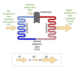
Figure 2-2 shows the three primary energy flows involved in the refrigeration cycle. The first energy input is low-temperature heat absorbed from the surrounding air into the refrigerant at the evaporator. The second energy input is electrical energy flowing into the compressor whenever it is operating. The third energy flow is the heat output from the condenser, which is transferred to the water in the storage tank.
The first law of thermodynamics states that, under steady state conditions, the total energy input rate to the heat pump must equal the total energy output rate. Thus, the sum of the rate of heat absorbed from the air surrounding the heat pump water heater, added to the rate of electrical energy input to the compressor, must equal the rate of energy dissipation from the refrigerant at the condenser. This is depicted by the arrows in Figure 2-2.
The basic refrigeration components represented in Figures 2-1 and 2-2 are present in all heat pump water heaters. There is also a fan to blow air across the evaporator coil. The size and placement of these components relative to each other is determined based on the “compartment” into which they must fit, as well as the heating capacity of the heat pump water heater.
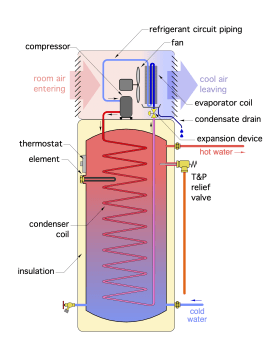
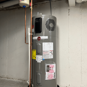
In a typical residential class heat pump water heater, most of the refrigeration components are housed in a module that’s attached to the top of a tank, as shown in Figure 2-3a,b.
The condenser portion of the refrigeration circuit consists of metal tubing that is either immersed in the tank water or wrapped around and bonded to the outside of the steel water tank. In either case, heat is transferred from the hot refrigerant gas passing through the tubing to the water in the tank. A small fan is used to move air surrounding the unit through the evaporator coil.
Some heat pump water heaters also have serviceable air filters to keep the surface of the evaporator coil as clean as possible. Most residential HPWHs also have one or two electric-resistance heating elements that can provide auxiliary or backup heating if the refrigerant circuit requires servicing.
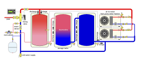
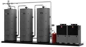
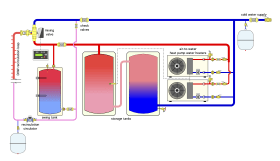
Commercial-scale heat pump water heaters have larger versions of the basic refrigerant system components but typically do not have an integrated storage tank. The condenser is housed in the same compartment as the other refrigeration system components, and domestic water is circulated between the heat pump and one or more storage tanks. Figure 2-4a shows the concept.
Figure 2-4b shows a configuration where two HPWHs supply three thermal storage tanks. The three tanks are piped in series. This helps create a “thermocline” region that separates the hot and cold water within the tanks. When the heat pumps are running and the flow through them is greater than the demand for domestic hot water, flow through the tanks is from left to right.
This supplies the heat pumps with the coolest water in the storage system, which increases their coefficient of performance (COP). When the heat pumps are off, or when flow to the building’s hot water distribution system is greater than the flow through the heat pumps, flow through the tank assembly will be from right to left.
Coefficient of Performance
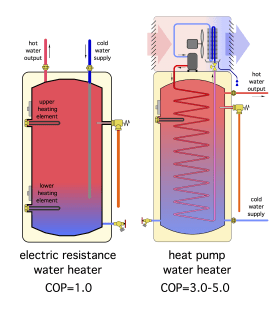
The primary advantage of using a heat pump water heater in comparison to an electric-resistance water heater, is that the majority of the heat added to the water came from the air surrounding the heat pump, rather than being created by an electric-resistance heating element (as it would with a standard electric water heater).
This advantage can be expressed as the coefficient of performance (COP), which in the case of a heat pump water heater can be expressed as follows:
Formula 2-1:
$$ COP={Q_{w} \over {[3.413](P_e)}} $$
Where:
$COP$ = coefficient of performance (a unitless number)
$Q_w$ = rate at which heat is added to water in storage tank (Btu/hr)
$P_e$ = electrical power input to operate water heater (watts)
$3.413$ = conversion factor to change watts to Btu/hr
For example: Assume a heat pump water heater transfers heat to the water in its storage tank at a rate of 30,000 Btu/hr, while operating with an electrical power input of 2,400 watts. It’s COP under this condition would be:
$$ COP= {Q_{w} \over {[3.413](P_e)}} = {30,000{{Btu} \over hr} \over \bigg[3.413{{Btu/hr} \over watt}\bigg] (2400watt)} = 3.66 $$
Notice that all the units on the physical quantities cancel out, leaving the $COP$ as a unitless number.
The $COP$ can be interpreted two ways.
1. It can be thought of as a multiplier on the rate of heat input to the water compared to the rate at which an electric-resistance heating element, operating at the same electric input power, would add heat to the tank. In this example, the heat pump water heater would be adding heat to the tank at a rate 3.66 times greater than an electric-resistance heating element, when both the heat pump and element are operating at 2,400 watts electrical input power.
2. The $COP$ can also be considered as a “divider.” The operating cost of a heat pump water heater running at a $COP$ of 3.66 would be (1/3.66) of the operating cost of an electric-resistance water heater, when both supply the same amount of hot water. This is the primary benefit to an owner paying for hot water service.
Another way to visualize the significance of COP of a heat pump water heater is the ratio of the rate at which heat is added to the water divided by the rate of electrical input to operate the heat pump. Figure 2-5 shows this concept as an extension of Figure 2-2. The large arrow at the top of the ratio represents the rate of heat delivery to the water. The small arrow represents the rate of electrical energy input.
The COP of a heat pump water heater will vary depending on the air temperature from which heat is being absorbed and the water temperature maintained in the storage tank. In general, the warmer the air temperature and the lower the water temperature setting, the higher the COP.
The COP of an electric-resistance water heater is always 1.0. Figure 2-6 shows a comparison between the COP of an electric-resistance water heater and a residential-scale heat pump water heater.

