Pressure independent control valves are the latest evolution of hydronic technology that offer the best opportunities for controllability and energy efficiency.
The pressure independent balancing valves (PIBV) discussed in the previous section allow a specific flow rate to be maintained over a wide range of differential pressures. However, they do not have the ability to start and stop flow, or the ability to vary the flow rate through a heat emitter or cooling coil.
The latter functions are often desirable to regulate the rate of heat transfer from a heat emitter or from the cooling coil within an air handler or fan-coil.
This functionality can be added to the basic operating characteristic of a pressure independent balancing valve. The result is known as a pressure independent control valve (or PICV).
PICVs are useful when the flow rate to a heat emitter or cooling coil needs to be regulated by a building automation system or other electronic controller in response to changes in the heating or cooling loads.
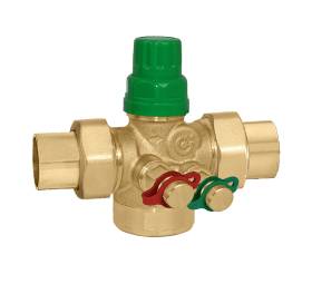
Figure 5-1 shows a Caleffi 145 Series FLOWMATIC® PICV valve. With the green manual adjustment knob as shown, this valve is an adjustable PIBV.
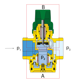
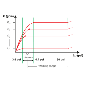
The lower portion of the valve (within box A) senses the pressure differential between the higher pressure (p2) and the slightly lower pressure (p3). The combined action of the diaphragm and spring in the lower portion of the valve maintain a nearly constant differential pressure (p2-p3) across the flow regulation chamber of the valve. This enables the valve to maintain a set flow rate over a wide range of differential pressure as shown in Figure 5-3.
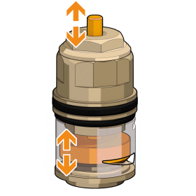
The upper portion of the PICV valve (within box B in Figure 5-2) combines a disc that moves up and down as the valve stem moves, with a tapered slot through which flow passes. These details are shown in Figure 5-4.
As the disc moves up and down, it acts like a “shutter” over the tapered slot, controlling the gap through which flow can pass.
For proper operation, the orientation of the tapered slot must be adjusted based on the maximum flow rate (G max) that will pass through the valve. This is easily done by loosening the locknut at the top of the valve and rotating the disc marked with number 1 through 10. Doing so rotates the shutter as required by the maximum flow rate.
A table that shows how to select the setting number is provided later in this section. Once the setting number has been adjusted, the lock nut is retightened. This adjustment does not affect the stroke of the stem, only the size of the flow aperture when the valve is fully open. This is an important feature because the proportional control signal to the valve's actuator is always fully utilized for the full stroke of the shaft, even when the maximum flow rate through the valve is reduced.
Once the position of the valve’s disc relative to its tapered slot has been set, the valve can function as an automatic balancing device capable of holding a set flow rate over a wide range of differential pressures between its inlet and outlet.
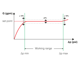
The relationship between the flow rate setting and the differential pressure range across which that setting can be maintained is shown in Figure 5-5.
The valve’s ability to hold a set flow rate requires that the differential pressure between its inlet and outlet be within the “working range” as shown in Figure 5-5.
The minimum differential pressure varies from 3.6 to 4.4 psi depending on the flow rate setting of the valve, which is adjusted using the numbered disc and lock nut on the valve’s bonnet. The upper limit of differential pressure at which the valve can maintain a set flow rate is 60 psi.
Adding An Actuator
The Caleffi 145 can also be operated automatically rather than manually by replacing the green knob with an actuator. These actuators allow flow through the valve to be regulated by any controller or building automation system (BAS) that can provide a standard 24 VAC on/off signal or a 0-10 VDC proportional control signal.
Adding an actuator changes the valve from an adjustable pressure-independent balancing device, to a pressure-independent control valve (PICV). Think of the latter as an enhancement that adds control capability to the basic functionality of the PIBVs described in section 4. This combination represents the state-of-the-art in achieving stable heating or cooling capacity control based on varying the flow rate through a heat emitter or cooling coil.
On/Off Control Of PICVs
When fitted with a thermo-electric actuator, the upper portion of the valve can operate as an on/off flow control device, much like a zone valve. However, unlike a typical zone valve, the pressure-regulating portion of the valve can maintain a constant flow rate through the valve over a wide range of differential pressures.
Changes in differential pressure across the valve are usually created by other valves in the system opening and closing. This is especially likely when a fixed-speed circulator provides flow in the system. On/off zone valves lack this pressure compensating ability, and as such, can allow significantly different flow rates unless other means of pressure compensation, such as variable-speed circulators, pressure-independent balancing valves, or differential pressure bypass valves, are used in the system.
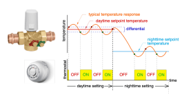
On/off flow control is often used when the control system is intended to maintain a quasi-steady room temperature based on a setpoint and differential typically coming from a room thermostat.
A standard room thermostat acts as a “switch” that provides either 0 VAC or nominal 24 VAC voltage to the valve’s actuator.
As the thermostat cycles power on and off to the actuator, it fully opens or fully closes the valve. This type of control results in “pulses” of heated water flowing through the room’s heat emitter. These pulses create variations in room temperature slightly above and below the “target” setpoint, as shown in Figure 5-6.
The on/off status of the valve’s actuator is shown at the bottom of the figure. The resulting fluctuations in room temperature above and below the setpoint temperature are shown in the upper portion of the figure. The slight overshoot and undershoot of the temperature are the result of the temperature differential controlling the actuator, as well as the thermal mass of the distribution system and heat emitters. Modern controllers can reduce this differential to limit overshoot and undershoot to nearly undetectable levels. On/off actuators have two advantages compared to proportional actuators; they are silent and they cost less.
Proportional Control Of PICVs
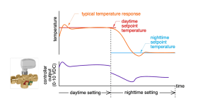
The Caleffi PICV valve can also be fitted with an actuator that takes a standard 0-10 VDC proportional signal from any proportional controller, such as a proportional thermostat, or building automation system (BAS). These controllers typically use PID (proportional integral derivative) control algorithms that compare the temperature setpoint to the actual room temperature.
The controller's 0-10 VDC output signal then drives the actuator/valve to quickly stabilize room temperature at the desired setpoint with very minimal overshoot or undershoot, as represented in Figure 5-7.
A PICV balancing valve equipped with a 0-10 VDC actuator and regulated by a PID temperature controller is analogous to a modulating heat source regulated based on outdoor reset. Both can quickly “zero in” on the target temperature setting and maintain that setting with essentially imperceptible variations.
PICV Applications
PICV valves can be used in either 2-pipe direct return distribution systems or 2-pipe reverse return distribution systems. They provide the functional equivalent of either a zone valve paired with an automatic balancing valve, or a static balancing valve paired with a modulating flow control valve.
For more information on direct return and reverse return hydronic distribution systems, see idronics #8.
PICV Sizing
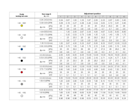
All PICV valves require a minimum differential pressure ($\Delta P$) to engage their pressure regulation function, as represented in Figure 5-3. The circulator driving flow through the system must provide this minimum $\Delta P$ in addition to the pressure drop of the piping and other components.
The differential required of the circulator under design load conditions can be determined by adding the pressure drop of all piping and other components in the flow path of highest resistance to the $\Delta P_{min}$ value in Figure 5-9, which is specific to the Caleffi 145 Series FLOWMATIC PICV valves.
This table shows the flow setting range of different size 145 Series valves (as numbered 1 through 10 along the top of the table). The minimum flow rate for the valve to maintain stable pressure regulation is shown under the column marked “1.” The maximum flow rate for stable pressure regulation is shown under the column marked “10.” The minimum differential pressure across the valve ($\Delta P_{min}$) is listed for each setting position in both metric and IP units.
For example, if the valve is to pass 3 gpm at design conditions, the 145…3G5 valve would be used, its setting number would be 9 (corresponding to 3.15 gpm in the table), and the minimum differential pressure required across the valve would be 4.1 psi
For more information on sizing variable-speed circulators for systems using PIBV or PICV valves, see idronics #8.
Coil Kits
PICVs are ideal for controlling the thermal output from an air handler, fan coil or chilled beam terminal unit in either heating or cooling.
When piping such a terminal unit, several components other than a standard PICV are typically used. These include valves for isolating the terminal unit from the remainder of the system, draining the isolated terminal unit if required, capturing debris that could interfere with operation of the PICV, and verifying the pressure drop across the assembly of these components combined with that of the terminal unit.
One approach is to individually specify all the components needed at each terminal unit, and assemble them on site. While this approach can work, it involves additional design, specification, installation and commissioning time. If the terminal unit uses chilled water for cooling, all these separate components must be insulated and vapor sealed to prevent condensation. Several joints are required, increasing the potential for leaks.
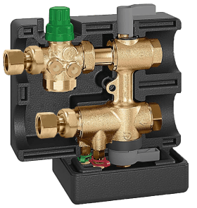
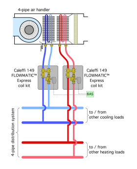
Caleffi offers a more efficient approach by combining all the functionality required into a single pre-assembled module called the 149 Series FLOWMATIC Express Coil Kit, which is shown in Figure 5-10.
The coil kit, combined with one of the valve actuators available for its PICV, provides all the functionality required to:
1. Control flow through a terminal unit.
2. Isolate that unit from the remainder of the system.
3. Allow flow to bypass the coil during system flushing.
4. Drain the isolated terminal unit.
5. Measure the ∆P across the PICV or the terminal unit and use it to calculate flow rate.
6. Collect debris in the flow stream.
7. Protect all components against condensation in chilled-water cooling applications.
Figure 5-11 shows how the FLOWMATIC coil kit compares to a shop- or field-assembled grouping of components that provides equivalent functionality.
The Caleffi FLOWMATIC coil kit is available in nominal pipe sizes from 1/2-inch to 1-inch. It can be hard-piped to the distribution mains and is connected to the terminal unit using flexible hose connections.
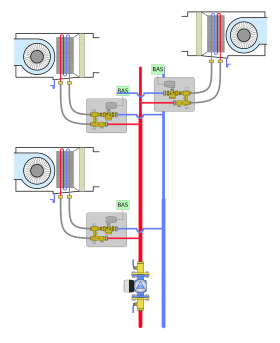
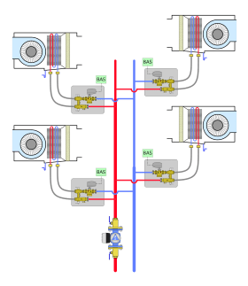
Installation of the coil kit in a 2-pipe distribution system requires two pipes connecting the distribution mains to the coil kit, and two pipes or flexible hoses to connect the coil kit to the terminal unit. Low-voltage wiring connecting the PICV valve actuator to the building’s control system is also required. Figure 5-12 shows a typical 2-pipe arrangement of independently-controlled air handlers, operating in heating mode, and supplied with Caleffi FLOWMATIC coil kits.

