PREFACE
Previous sections have described the advantages of using hydronic heating and cooling in low-energy and net-zero buildings. Simple and repeatable concepts have been shown along with a range of appropriate hardware. This section brings those concepts together to form several complete systems. They range from space heating only, to systems that also provide domestic hot water and cooling.
These systems show a “diversity” of heat sources, such as split-system and monobloc air-to-water heat pumps, geothermal water-to-water heat pumps and electric boilers. Any of the heat pump types represented can be “swapped” for one of the other types, along with any necessary details (such as the use of antifreeze with a monobloc air-to-water heat pump). This “swapping” concept is also true for the loads shown. A given system could use different heat emitters, or different methods of producing domestic hot water, relative to those shown. Any of the heat pump-based systems could include chilled-water cooling. Any of the systems using heat pumps could also include an electric or fossil-fuel boiler as a supplemental and backup heat source This concept of interchangeable sub-assemblies provides enormous flexibility in configuring systems to the exact needs of each project.
SYSTEM #1
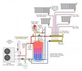
The system shown in Figure 5-1 provides space heating and domestic hot water. It uses a monobloc air-to-water heat pump with a single-speed compressor and a reverse indirect water heater. The latter serves as a buffer tank and domestic hot water source.
Space heating is provided by 6 individually controlled panel radiators. Each radiator is sized for the design heating load of its associated space when operating at a supply water temperature of 120ºF, with a 20ºF temperature drop, and thus an average water temperature of 110ºF. During partial load conditions, the water temperature in the buffer tank is reduced based on outdoor reset control. This maximizes the seasonal COP of the heat pump, while also ensuring that the supply water temperature to the radiators is high enough to maintain comfort.
Each radiator is equipped with a thermostatic operator and supplied by a pair of 1/2-inch PEX tubes that begin and end at a manifold station. The latter has two additional sets of connection ports to allow other heat emitters to be easily added in the future. Flow to all radiators is provided by a variable-speed pressure-regulated circulator that operates continuously during the heating season. The speed of this circulator automatically changes as the thermostatic operators on the radiators open, close or modulate flow. If all radiator valves are closed, the circulator goes into a low-power “sleep” mode, typically drawing less than 10 watts of electrical power. The sleep mode ends as soon as a radiator valve begins to open.
The majority of the domestic water heating takes place whenever hot water demand at a fixture pulls cold water upward through the copper coils inside the buffer tank. Any additional temperature rise needed to bring the domestic water to the desired delivery temperature is provided by an on-demand electric water heater. During late spring, summer and early fall, when space heating is not required, it would be possible to increase the temperature setting of the outdoor reset controller to allow the heat pump to fully heat domestic water to 120ºF. The on-demand electric water heater could be turned off during this time.
To protect the heat pump from freezing, the entire system operates with a 30% solution of non-toxic propylene glycol antifreeze.
SYSTEM #2
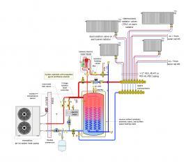
This system adds an electric boiler and associated details to system #1. This boiler can provide supplemental heat input if needed during extremely cold weather. It can also serve as a backup heat source if the heat pump is down for servicing.
A 2-stage controller manages operation of both the heat pump and electric boiler. It’s objective is to maintain the buffer tank at a target temperature based on outdoor reset control. This controller provides a 10-minute time delay between activating the heat pump and possibly activating the electric boiler. This allows time for the heat pump to stabilize its initial operation and gives the controller time to “decide” if a second stage of heat input is needed.
Motorized ball valves are installed in the piping for each heat source. They open when their associated heat source is on and close at all other times. These valves prevent reverse thermosiphon flow from the buffer tank through the piping of either heat source when that heat source is off. They also prevent reverse flow through one heat source when the other heat source is on. Finally, they prevent flow returning from the manifold station from inadvertently passing through either heat source when it is off.
Domestic water is heated the same way it was in system #1.
SYSTEM #3
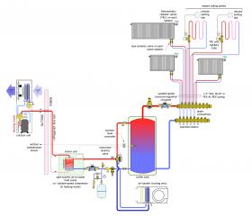
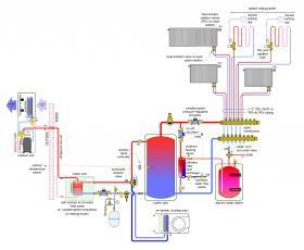
This system uses a split-system air-to-water heat pump with an inverter drive compressor to provide space heating and cooling.
Space heating is provided by a combination of panel radiators and low-thermal mass radiant ceiling panels, all operating at the same supply water temperature and connected as a homerun distribution system. A variable-speed pressure-regulated circulator provides flow to this distribution system and automatically adjusts its flow rate and power input as the thermostatic valves on the radiators and radiant ceiling panel circuits open and close.
The 3-way motorized diverting valve opens between the AB and A ports when the heat pump operates in heating mode, and closes between these ports at all other times. This prevents reverse thermosiphoning between the buffer tank and heat pump when it’s off. During cooling mode, the motorized valve routes flow between its AB and B ports. The heat pump’s compressor speed automatically adjusts to maintain a chilled-water outlet temperature of 50ºF to the air handler.
The system includes a DIRTMAG® PRO separator to ensure that the heat pump condenser and the circulators supplying the heat pump remain clean of dirt and magnetic particles (e.g., magnetite). The manifold station includes additional connections that allows more heat emitters to be easily added in the future.
SYSTEM #4
This system shows one way to add domestic water heating to system #3. It uses an external stainless steel brazed-plate heat exchanger mounted close to the buffer tank to transfer heat into cold domestic water whenever the demand for domestic hot water reaches 0.7 gpm or higher.
This threshold is determined by a flow switch mounted in the cold water pipe leading into the heat exchanger. The temperature of the domestic water leaving this heat exchanger depends on the buffer tank temperature, which itself is regulated by outdoor reset control. In most cases, this temperature will be lower than the desired DHW delivery temperature. This system uses a standard tank-variable-type electric water heater to boost the preheated water to its final delivery temperature. This tank could also provide 100 percent of the DHW load if the heat pump is down for service.
For more information on sizing heat exchangers for domestic water heating applications:
SYSTEM #5
A low-energy or net-zero home could also be fully heated by an electric boiler. An ideal application would be a home with a high-performance thermal envelope in a cold climate that doesn’t require cooling, and where electrical rates are relatively low. In this scenario, the electric boiler may have a lower life-cycle cost compared to a heat pump.
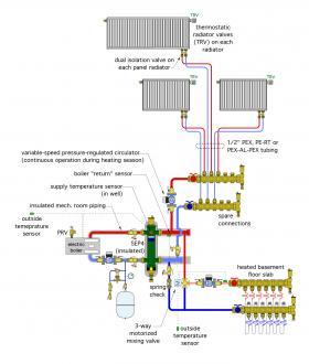
The system shown in Figure 5-5 shows one example of how an electric boiler can be configured to supply a heated floor slab in the basement and three panel radiators on the home’s main floor.
Although electric boilers can operate at elevated temperatures without a decrease in efficiency, there are advantages associated with sizing the panel radiators for a relatively low water supply temperature, such as 120ºF, under design load conditions. Doing so allows the possibility of using a heat pump as a future heat source without having to add heat emitters or increase the size of existing emitters. It also allows the radiators to have a higher percentage of radiant versus convective heat output, which improves comfort. Heat loss from the distribution piping is also reduced when the system operates at lower water temperatures.
All-electric boilers require a minimum sustained flow rate whenever they operate. In this system, that flow is provided by a dedicated low-power ECM circulator that operates continuously during the heating season. The SEP4™ hydraulic separator and the short/generously sized headers ensure that all three circulators are hydraulically isolated from each other. It also provides air, dirt and magnetic particle separation for the system. The three panel radiators are supplied by a homerun
distribution circuit powered by a variable-speed pressure-regulated circulator. Each panel radiator is equipped with a dual isolation valve and a thermostatic operator. The latter allows each radiator to adjust its heat output to meet the desired comfort level in the space served by that radiator.
The floor-heating circuits in the basement are supplied through a 3-way motorized mixing valve, which reduces the supply water temperature relative to that supplied to the panel radiators. The boiler piping, SEP4 hydro separator, and surrounding
metal piping should be insulated to minimize heat loss to the building’s mechanical room.
This system combines a very high thermal mass heat emitter (e.g., the heated basement slab), with other very low thermal mass heat emitters (e.g., the three panel radiators). This combination sets up the possibility that the high mass slab can absorb much of the heat supplied by the boiler, especially if that slab is warming from a cool starting condition. This transient condition can significantly depress the water temperature in the entire system and not allow the panel radiators to properly heat their associated spaces. In effect, the slab’s mass will “dominate” where heat from the boiler is going.
To avoid this undesirable temperature depression, the system needs to operate in one of two possible control configurations.
Configuration #1: Provide ALL of the following requirements:
- Operate the boiler and its circulator continuously during the heating season, with the water temperature based on full outdoor reset control. The outdoor reset settings should allow the panel radiators to maintain room comfort on a design load day. Most modern electric boilers have internal controllers that allow for outdoor reset control.
- Operate the panel radiator circulator and the floor-heating circulator continuously during the heating season.
- Configure the mixing valve controller for outdoor reset with settings sufficient to maintain the basement comfort level on a design load day.
- Equip the mixing valve controller with indoor temperature feedback, which eliminates the need for a thermostat in the basement.
- Do not make frequent adjustments (such as nighttime setback) to the desired basement air temperature.
Configuration #2: Provide ALL of the following requirements:
- Operate the boiler and its circulator continuously at a setpoint temperature high enough to allow the panel radiators to maintain room comfort on a design day. A suggested not-to-exceed temperature is 120ºF.
- Install the boiler “return” temperature sensor — supplied with the mixing valve controller — on the outlet of the SEP4 hydro separator, and set the minimum boiler return temperature setting on this controller 2ºF lower than the supply water temperature required by the panel radiators on a design day. This allows the controller to partially close the mixing valve’s hot port as necessary to prevent a temperature drop that would otherwise limit the output from the panel radiators.
Control configuration #1 reduces piping heat losses, but also counts on “consistent” operation of the basement floor-heating subsystem (e.g., not making frequent changes in the desired room temperature setting for the basement).
Control configuration #2 allows for frequent changes in the desired temperature setting for the basement. It also ensures that the panel radiators will have sufficient supply water temperature to maintain comfort in their associated spaces. However, this configuration will result in higher heat losses from the distribution piping. If used, it is essential to insulate all metal piping and piping components within the mechanical room.
Either control configuration is possible. The choice will likely be based on how the air temperature of the basement will be (or won’t be) changed.
SYSTEM #6
Another possible application for an electric boiler in a low-energy or net-zero house is when the local utility offers time-of-use electrical rates, and the boiler can be combined with thermal storage. The objective is to operate the electric boiler as much as possible during times when low-cost “off-peak” rates apply, and keep the boiler off when possible during times when “on-peak” rates apply.
Time-of-use rate structures vary among utilities. Most provide their lowest rates from late night to early morning. Some utilities also offer off-peak rates on weekends and holidays. One example of a time-of-use rate structure would be:
- Between 11:30 PM and 7:00 AM weekdays, and between 11:30 PM Friday and 7:00 AM Monday, electricity is priced at $0.05/kWhr.
- Between 7:00 AM and 11:30 PM weekdays, electricity is priced at $0.20/kWhr.
The feasibility of an off-peak thermal storage heating system depends on the utility rate structure, the building load, the thermal mass available for storing heating, and to some extent, the willingness of the occupants to “cooperate” with the system’s operating objectives. Buildings with high-performance thermal envelopes can use smaller and less expensive thermal storage systems. Owners willing to reduce room temperatures, if necessary, during the final hours of an on-peak rate period will also help the system minimize operating cost.
Low-energy or net-zero buildings with grid-connected/net-metered solar photovoltaic systems are good candidates for this type of system. The solar electric system is likely to produce most of its output during times when on-peak utility rates apply. This solar-derived electricity would minimize the need for higher priced on-peak electricity from the utility grid, especially in situations where the electric boiler might have to operate during on-peak times.
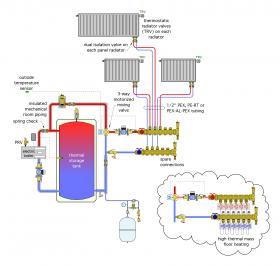
Figure 5-6a shows a possible system configuration in which an electric boiler supplies heat to a thermal storage tank, and ultimately to a homerun distribution system supplying panel radiators. An alternative high-thermal mass floor-heating distribution system is also shown.
The controls for this system turn on the electric boiler and its circulator at the start of each off-peak period. The boiler and its circulator remain on until the thermal storage tank temperature reaches 180ºF. Space heating can take place during this time, with excess boiler output routed into thermal storage. In this system, the panel radiators are sized to deliver design load output at a relatively low supply water temperature of 110ºF. Doing so allows for the thermal storage tank to be “discharged” to a relatively low temperature while still supplying adequate heating capacity to the radiators.
The amount of heat stored in the tank is 8.33 Btu/gallon/ºF. Thus, a 119-gallon tank undergoing a temperature discharge from 180 to 110ºF would release 8.33 x 119 x (180-110) = 69,390 Btus. This could represent several hours of heating in a low-energy or net-zero home, especially during partial load conditions.
The 3-way motorized mixing valve blends hot water from the thermal storage tank, or coming directly from the electric boiler, with cooler water returning from the radiators to achieve a target supply water temperature to the radiators. That target temperature is based on outdoor reset control. The latter allows the tank to supply the radiators down to the minimum water temperature that can still maintain comfort in the building. On partial load days, that temperature could be in the range of 80ºF. The lower this temperature can be, the greater the amount of heat the tank can deliver to the load on each discharge cycle.
If the tank cools to the point where the radiators can no longer maintain comfort, as determined by some minimum tank temperature, the electric boiler is enabled to operate regardless of which electrical rate is in effect. Boiler operation during on-peak periods should be minimized to keep overall operating cost low. This situation would typically occur during early evening hours, when the output of a solar electric system is low or zero, and internal loads in the building tend to diminish.
The alternative concrete slab floor-heating system adds substantial thermal mass to the system, extending its ability to maintain comfort in the building for longer periods when on-peak electrical rates are in effect. For example, a 4-inch-thick concrete slab can store 9.8 Btu/square foot/ºF of temperature change. A 6-inch-thick slab can store 14.7 Btu/square foot/ºF of temperature change. Thus, a 1,500-square-foot slab, 4 inches thick, and undergoing an average temperature drop of only 3ºF, can release 44,100 Btus.
A word of caution is appropriate. High-thermal mass distribution systems, although good at storing heat, and thus allowing buildings to “coast” through several hours without heat input from source equipment, are not well-suited to buildings where significant and unanticipated internal heat gains might occur. This type of system should not be used in buildings that are designed for significant solar heat gain, or where a large number of occupants or other heat-generating activities may be present at times.
It is also critically important to insulate all piping and components in areas of the system that are subject to high water temperatures. Be sure that all components used are rated to handle the highest water temperatures that might be present. The system shown in figure 5-6a also uses several spring-loaded check valves to limit heat migration within the system.
The thermal storage tank, piped as shown in Figure 5-6a allows the electric boiler to operate at or above its minimum flow rate, even when only a “trickle” of hot water is passing into the 3-way mixing valve. It also provides hydraulic separation between the boiler circulator and the distribution circulator. Another variation on the system is shown in Figure 5-6b.
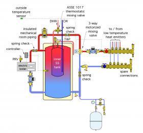
This system uses a “tank-in-tank” reverse indirect water heater for thermal storage. Heat added to this tank by the electric boiler can be used for either space heating or for domestic water heating. The latter occurs within the inner stainless steel tank.
If the temperature in the tank shell is maintained at or above 120ºF, the domestic water should be fully heated to a reasonable distribution temperature by the time it leaves the inner tank. If the minimum tank temperature will be lower, some type of auxiliary electric water heater (tankless or tank-type) could be added to boost the domestic water to its final desired temperature.
An ASSE 1017-listed thermostatic mixing valve, installed as shown in Figure 5-6b, is critically important to ensure that the domestic water leaving the tank doesn’t exceed 120ºF.
SYSTEM #7
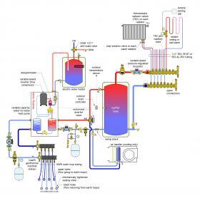
This system provides multi-zone heating using a combination of low-temperature, low-thermal mass panel radiators and radiant panels. It also provides a single zone of chilled-water cooling, and domestic-water heating. A variable-capacity geothermal-sourced water-to-water heat
pump serves as the primary heating and cooling source.
The heat pump is supplied from a closed earth loop system consisting of four buried HDPE earth loop circuits piped in parallel. All the earth loop circuits begin and end at a Caleffi GeoCal™ manifold station, which allows each circuit to be individually isolated and flushed. Since the manifold station is inside the building, it is possible to install the entire earth loop without having to thermally fuse the HDPE pipe. The earth loop subsystem includes an expansion tank as well as a Caleffi DISCALDIRTMAG® separator, which removes air, dirt and magnetic particles from the earth loop fluid.
During heating mode, the heat pump maintains the buffer tank temperature based on outdoor reset control. This keeps the water in the buffer tank just warm enough to ensure that comfort is maintained, while also maximizing the heat pump’s COP. All heat emitters are connected to a single homerun distribution system supplied from the buffer tank. Flow through the heat emitters is controlled by a variable-speed pressure-regulated circulator. All heat emitters are sized to meet the design loads of their associated building spaces using a supply water temperature no higher than 120ºF.
Single-zone cooling is provided by a chilled-water air handler. The inverter-driven heat pump varies its cooling capacity as necessary to maintain a chilled-water outlet temperature of 45ºF. Domestic water is heated by the heat pump’s desuperheater whenever the heat pump’s compressor is on. A small stainless steel circulator within the heat pump moves cool domestic water from the lower portion of the tank-type water heater through the desuperheater and back to the tank. Any final temperature boost needed is provided by an electric resistance heating element in the upper portion of the tank.
For more information on geothermal heat pump systems:
Summary
Demand for net-zero buildings is rapidly increasing across North America and globally. The majority of buildings designed to operate on a net-zero energy basis use electrically powered heat sources and cooling sources in combination with site-generated electricity from solar photovoltaic systems. Heat pumps of several types are commonly used for heating and cooling. Among these are air-to-water and water-to-water heat pumps, both of which are ideally suited to hydronic system applications.
By combining modern heat pump technology with hydronic heating and cooling distribution systems, designers can achieve benefits not possible with forced-air distribution systems. These include superior comfort, radiant as well as convective heat delivery, high distribution efficiency, minimally invasive installation, the ability to heat domestic water, the ability to coordinate with time-of-use electrical rates, adaptability of the distribution system to future heating and cooling sources, and a long service life.
The legislative, cultural and economic incentives that encourage beneficial electrification and decarbonization, and the accompanying demand for low-energy and net-zero buildings, collectively represent one of the biggest opportunities set before the North American hydronics market in decades. The concepts and details presented in this issue serve as building blocks that creative designers can assemble into systems that meet this demand and are precisely tailored to the needs of each building.

