PREFACE
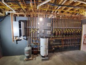
Some of those who design or build low-energy and net-zero buildings have preconceived notions about hydronic systems. Their opinion is that such systems are overly complicated and unnecessary in these contemporary buildings.In hindsight, the North American hydronics industry is largely responsible for cultivating these opinions by showcasing unique and elaborate installation photos. Figure 4-1 is an example.
This system uses a nominal 5-ton split-system air-to-water heat pump as its source equipment. Several of the ten circulators visible in the photo have high-efficiency ECM motors. The craftsmanship evident by the piping and electrical work is outstanding. This system certainly combines the concepts of heat pumps and modern hydronic system design, and likely delivers the goals for which it was custom designed.
Still, this system required hundreds of components to be properly selected, purchased, organized into a coherent design, and at least in part — field assembled. As such, this image can be overwhelming to architects, general contractors or owners looking for a simple, affordable and serviceable solution to heating and cooling a home with low space heating and cooling loads. The perceived complexity, cost or reliability of such a system often dissuades these building professionals or the eventual building owners from using hydronic-based systems.
The hardware-intensive approach to hydronic heating and cooling survives as a niche in the market, but mostly for custom-built new homes with generous construction budgets. This niche approach is unlikely to be adapted as a “go-to” solution by professionals designing low-energy and net-zero homes, especially when several alternatives compete for the mechanical system portion of the construction budget.
Hydronic systems for low-energy and net-zero buildings should:
- Meet owner expectations for installed cost, reliability, serviceability, aesthetics, embodied carbon and recyclability.
- Provide superior thermal comfort in both heating and cooling modes.
- Provide an option for domestic water heating in addition to space heating and cooling.
- Recognize the unique load and thermal response characteristics of low-energy and net-zero buildings.
- Harmonize with the construction techniques and materials used in low-energy and net-zero buildings.
- Use simple, repeatable and scalable concepts.
- Enhance heat pump performance wherever possible.
- Minimizes electrical power demand (e.g., high distribution efficiency).
- Considers new delivery modes for electricity (e.g., real time pricing, onsite battery storage, load shifting and demand-limiting possibilities).
- Allows continuity of operation under unexpected conditions (resiliency).
- Consider use of existing boilers in retrofit projects.
This section will show and describe methods and hardware that address these design concepts.
HEAT EMITTER OPTIONS
There are dozens of devices and site-constructed assemblies that can serve as hydronic heat emitters. They range from concrete slabs with embedded tubing, to fan-assisted panel radiators, to extended surface-area fin-tube baseboards. These devices cover a wide range of thermal mass and supply water temperature requirements. They also cover a wide range of installation cost and complexity.
There may not be a “perfect” heat emitter selection that meets all of the previously stated system design objectives. For example, a heat emitter option that meets all of the technical requirements may not meet the owner’s expectation for cost or aesthetics. Thus, heat emitter selection is often a compromise based on the “weight” the owner and system designer assigns to each of these design objectives.
In the context of low-energy and net-zero buildings, two technical characteristics should be given strong consideration:
- The thermal mass of the heat emitter(s).
- The supply water temperature required by the heat emitter(s) under design load conditions.
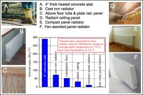
The thermal mass of different hydronic heat emitters can greatly influence the comfort achieved and maintained in a low-energy or net-zero building. Figure 4-2 shows a sampling of thermal masses for several hydronic heat emitters. The numbers in the chart are based on the “amount” of heat emitter needed to release 1,000 Btu/hr into a room at 70ºF, while operating at an average water temperature of 110ºF. Note that the thermal mass for a heated 4-inch concrete slab is over 100 times that of a modern fan-assisted panel radiator.
Heat emitters with high thermal mass take much longer to adjust to changing load conditions compared to heat emitters with low thermal mass. This has both desirable and undesirable implications. For example, a high thermal mass heated slab can often maintain reasonable comfort within a well-insulated building for several hours during a power outage, or during a pre-scheduled time when high cost electricity rates apply, and thus an electrically powered heat source might be intentionally turned off. During these times, the slab slowly releases stored heat without simultaneously receiving heat input. This is a very desirable characteristic under these circumstances.
However, the same heated slab installed in a building with large amounts of solar heat gain or other “unpredictable” internal heat gains can create wide variations in interior temperature due to its inability to quickly stop emitting heat.
Most currently constructed low-energy and net-zero buildings have high-performance thermal envelopes, and thus low rates of heat loss. These buildings are often designed and sited to take advantage of solar heat gains. Given these characteristics, along with the goal of maintaining stable comfort, it is typically best to use low thermal mass heat emitters in these buildings. Preferred options include panel radiators, fan-coils and radiant ceiling panels. These emitters can quickly deliver heat when needed, and just as importantly, they can quickly stop delivering heat when overheating is imminent.
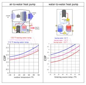
Another important consideration is the supply water temperature required by the heat emitter under design load conditions. When heat pumps are used as the system’s heat source, the lower the supply water temperature can be, while still maintaining interior comfort, the more efficient the heat pump (measured as the heat pump’s coefficient of performance COP). Figure 4-3 shows representative COP characteristics for a low-ambient air-to-water heat pump and a geothermal water-to-water heat pump.
Notice that the COP of both heat pumps is strongly dependent on the water temperature leaving the condenser (as represented by the three curves on each graph). The lower this temperature, the higher the heat pump’s COP. Heat emitters that can meet design heating loads using supply water temperature no higher than 120ºF are generally well-suited for use with heat pumps. Under partial load conditions the water temperature leaving the heat pump can be reduced based on outdoor reset control. This maximizes the heat pump’s COP while ensuring that comfort is maintained in the building.
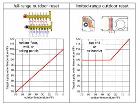
When panel radiators or radiant ceiling panels are used, it’s possible to use “full-range” outdoor reset control. When fan-coils are used, supply water temperature should generally not be reduced below 100ºF, regardless of the load. This helps prevent low-temperature air currents that, while able to maintain the space’s setpoint temperature, could create uncomfortable drafts. Air streams from fan-coils or air handlers capable of operating at low water temperatures should be carefully designed to mix with room air in areas away from where occupants would likely be seated. Ceiling diffusers with a wide spread and short throw, or high-wall diffusers with a long throw and minimal spread will help in this regard.
Both “full-range” and “limited-range” outdoor reset are shown in Figure 4-4.
For a given rate of heat output and room air temperature, the average water temperature at which any hydronic heat emitter needs to operate depends on its surface area. The larger the surface area, the lower the average water temperature. This relationship can be represented by Formula 4-1.
Formula 4-1:
$$ q=c[f_c]A(T_w-T_R)^n $$
Where:
$q$ = heat output of the emitter (Btu/hr)
$c$ = a constant based on the construction or geometry of the emitter (determined by testing)
$fc$ = flow rate correction factor (determined by testing)
$A$ = surface area of the emitter (ft2)
$T_w$ = average water temperature inside the emitter (ºF)
$T_R$ = room air temperature (ºF)
$n$ = an exponent based on the type of heat emitter
The ASHRAE (HVAC Systems & Equipment) Handbook suggests the following values for the exponent n in Formula 4-1:
- for radiators, n = 1.3
- for fin-tube baseboard, n = 1.4
- for ceiling heating or floor cooling, n = 1.0
- for ceiling cooling and floor heating, n = 1.1
This relationship between surface area and required water temperature allows a site-built radiant panel in a low-load building to operate at very low average water temperatures. For example, the average surface temperature of a heated floor supplying an upward output of 10 Btu/hr/ft2 only needs to be about 5ºF above the air temperature in that space. Assuming 12-inch tube spacing, 70ºF interior air temperature, and a bare or stained concrete slab-on-grade floor, the average water temperature in the embedded tubing circuits only needs to be about 81ºF. The supply water temperature to the panel would likely be in the range of 86 to 91ºF. While this allows a heat pump to operate at very high COPs, it can also lead to disappointment by owners who expect a heated floor to feel warm. A surface temperature of 75ºF is slightly below normal skin temperature. A floor surface at this temperature would feel “neutral” at best to a bare foot.
The take-away from this scenario is to be sure that prospective owners of a low-energy or net-zero house who elect to use floor heating are aware of the fact that the floors will not feel noticeably warm, even though the space is being maintained at normal interior temperature. If this is understood and acceptable, floor heating remains an option. If this dissuades the owners based on expectations of noticeably warm floors, other heat emitters options are a better choice.
LOW THERMAL MASS RADIANT PANELS
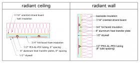
One radiant panel construction that can be used on ceilings as well as walls is shown in Figure 4-6.
In this construction, the 1/2-inch PEX-AL-PEX tubing is spaced 8 inches apart. The aluminum heat spreader plates are 5 or 6 inches wide. The 3/4-inch foil-faced polyisocyanurate foam insulation strips are bonded to the 7/16-inch OSB substrate using contact cement. One rear half of each heat transfer plate is also bonded to the foam strips using contact cement. After the tubing circuits are pressed into the plates and pressured tested, the assembly is covered with 1/2-inch drywall. 2.5-inch-long drywall screws are installed halfway between adjacent tubes and spaced 12 inches apart in the direction parallel with the tubes.
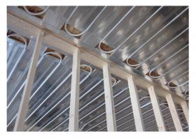
Figure 4-7 shows an example of a radiant ceiling panel using this construction. All components other than the 1/2- inch drywall finish are in place.
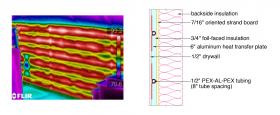
Figure 4-8 shows an infrared thermograph of the same panel construction turned 90º to create a radiant wall.
The colors in the thermograph image represent surface temperatures on the finish wall surface (e.g., the painted surface of the drywall). A scale showing the range of temperature captured is seen on the right side of the image. The red areas show the effectiveness of the aluminum heat transfer plates in spreading heat emanating from the tubing across the surface of the panel.
Radiant wall panels should be planned so that the space in front of them will not be blocked by furniture or other objects in the room. They can be installed from floor level up to approximately 8 feet high. Radiant walls can also be used in areas such as swimming pool enclosures or walk-in showers. In these applications, the drywall would be replaced by water-resistant backer board and ceramic tile.
The rate of heat emission to the room from the radiant ceiling or radiant wall assemblies shown in Figures 4-6 and 4-8 can be estimated using Formula 4-2.
Formula 4-2:
$$ q=a \times (T_{wa}-T_{room}) $$
Where:
$q$ = heat output of ceiling panel (Btu/hr/ft2)
$a$ = 0.71 for ceiling applications, or 0.80 for wall applications
$T_{wa}$ = average water temperature in panel (ºF)
$T_{room}$ = room air temperature (ºF)
The radiant panel construction shown in Figure 4-6 has relatively low thermal mass, and thus can quickly respond to internal heat gains. Heated ceilings have the advantage of not being covered or blocked by carpeting or furniture, and thus, are likely to retain good performance over the life of the building. They are also ideal surfaces for radiant cooling using chilled water supplied from a heat pump. However, when radiant cooling is used, it is critical to maintain the chilled-water temperature supplied to the distribution system above the dewpoint of the interior air.
For information on other radiant floor constructions, such as slab-on-grade and underfloor tube & plate systems, which may be suitable for some low-energy and net-zero building applications:
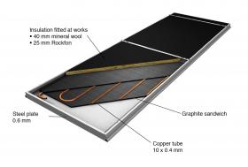
These applications typically use a modular system of prefabricated hydronic panels supported by a T-bar suspended-ceiling system. Figure 4-9 shows the construction of one such modular panel.
These panels are available in nominal widths of 24 inches, and nominal lengths ranging from 24 to 120 inches. Each panel consists of a painted steel frame pan into which is fitted a copper tube circuit, graphite heat diffusion layers and top-side insulation. The graphite layers provide lateral heat conduction between the tubing and panel areas between the tubing. Although these panels are relatively light, they still require support from light gauge chain or steel cables connected to structural elements such as bar joints or concrete slabs.
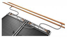
Figure 4-10 shows an example of how these panels can be quickly connected to supply and return piping using corrugated stainless steel tubing (CSST) hose sets.
When used for cooling, radiant panel systems must be designed and operated so that condensation cannot form on the panel or connected piping. This requirement is typically managed by automatic mixing of chilled water from the source equipment (e.g., heat pump or chiller) with water returning from the panels such that the supply water temperature is slightly above the current dewpoint temperature in the conditioned space. More information on radiant cooling is available in:
PANEL RADIATORS
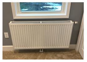
Generously sized panel radiators are an excellent heat emitter option for low-energy and net-zero buildings supplied by hydronic heat pumps. These steel panels are available in a wide range of sizes from several manufacturers. They have relatively low thermal mass per unit of heat output, and thus respond quickly to internal heat gains or temperature changes. They are also relatively light and easy to install.
One type of panel radiator, often called a “compact” panel, is supplied with an integral valve, which is mounted at the upper right corner of the panel. Figure 4-11 shows an example of this type of panel radiator.
All flow through this type of radiator must first pass through its integral valve. The radiator’s heat output can be regulated by varying the flow rate through it. This could be done manually, but like many manually adjusted processes, would require repeated adjustment to keep the radiator’s heat output matched to the room’s heating load.
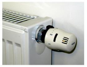
A much-preferred approach is to attach a thermostatic operator to the radiator’s valve, as shown in Figure 4-12.
This non-electric thermostatic operator continuously senses room temperature and automatically adjusts flow through the radiator to maintain the space very close to a desired comfort level.
When the radiators in a hydronic distribution system are equipped with these operators, each one can automatically and independently adjust its heat output to maintain the desired comfort level in the space where it’s located. This ability is especially beneficial in low-energy and net-zero buildings where each room may be subject to different and variable internal heat gains. Thermostatic operators are relatively inexpensive, require no wires or batteries, and are easily installed on the radiator’s integral valve.
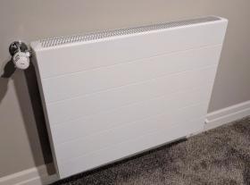
Other types of panel radiators are supplied without integral valves. However, the same zoning and control concepts can be used by installing a thermostatic radiator valve on the inlet connector to each radiator, as shown in Figure 4-13.
When panel radiators are to be supplied by an air-to-water heat pump or geothermal water-to-water heat pump, they should be sized to provide the design heating load of their associated space at relatively low water temperatures. A suggested guideline is to size each radiator for design load output of its associated space when supplied with water no hotter than 120ºF. This is within the operating range of both air-to-water and geothermal water-to-water heat pumps. Under partial load conditions, the water temperature can be further reduced using outdoor reset control. Doing so will increase the seasonal average COP of the heat pump.
The heat output of any panel radiator depends on its total surface area, the average water temperature at which it operates, and the room air temperature where the radiator is installed. Many manufacturers list the output of their panel radiators at relatively high average water temperature (180ºF is typical), along with an assumed room air temperature of 68ºF. This average water temperature is much higher than can be attained using current-generation air-to-water or water-to-water heat pumps. However, it is possible to “de-rate” the listed output of panel radiators based on lower average water temperatures, different temperature drops between supply and return flows, and when necessary, different room air temperatures. Appendix B summarizes the EN442 method for adjusting panel radiator outputs over a wide range of conditions.
FAN-ASSISTED PANEL RADIATORS
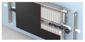
One of the newest low-temperature heat emitters is a fan-assisted panel radiator. These units use an array of small, low-power fans installed between the front and back surfaces of the panel. The fans automatically change speed based on room temperature relative to setpoint. They significantly increase convective heat output at low supply water temperatures. Each fan only requires about 1.5 watts of electrical power at full speed, and thus, electrical energy consumption is negligible, especially when compared to the electrical energy savings associated with operating the heat pump at lower water temperatures and higher COPs.
Fan-assisted panel radiators can operate at water temperatures as low as 95ºF. They have integral controls that can be set for a “boost” mode (e.g., full-speed fan operation) when the system is recovering from a setback temperature. These radiators are ideal for use with hydronic heat pumps.
FAN-COILS
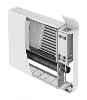
Several companies now offer hydronic fan-coils that can be used for heating, and in many cases, for chilled water cooling. The latter function requires the fan-coil to have a condensate drip pan and drain connection. Figure 4-15 shows an example of such a fan-coil.
This fan-coil combines a large surface-area “coil” made of copper tubing with aluminum fins with a low-power tangential blower located under the coil. The large coil allows for good heat output at relatively low supply water temperatures. The fan coil shown in figure 4-15, sized at 24 inches high and 32-inches wide, can release 6,700 Btu/hr while operating at an average water temperature of 110ºF. As with the previously discussed heat emitters, a suggested guideline is to size and select fan-coils that can release the design heating load of the space they serve while operating with supply water temperatures no higher than 120ºF.
One significant benefit of fan-coils equipped with drip pans, relative to panel radiators or site-constructed radiant panels, is their ability to provide both sensible and latent cooling when supplied with chilled water. The combination of one or more fan-coils with either an air-to- water or geothermal water-to-water heat pump is a relatively simple way of providing cooling to some or all areas of a net-zero building.
The fan-coil(s) could be used for cooling only, or for both heating and cooling. A cooling-only application would require other selections for heat emitters, and thus cost more than using the fan-coil(s) for both heating and cooling. However, the use of panel radiators or radiant panels for heating provides radiant and convective output that’s better-matched to human physiological comfort requirements.
It’s also important for owners to know that any fan-coil emits some sound while operating. The sound level of modern fan-coils is relatively low. For example, the fan-coil shown in Figure 4-15 emits sound measured between 25 and 48 decibels (depending on blower speed), and measured approximately 8 feet away from the unit. For comparison, a modern refrigerator emits about 50 decibels.
The cooling performance of fan-coils is based on the temperature of chilled water supplied to the coil. Lower water temperatures improve both sensible and latent cooling capacity. Designers need to assess the sensible and latent ratings of perspective fan-coils to ensure adequate overall cooling. Heat pump performance (e.g., both cooling capacity and EER) increases as chilled-water temperatures increase. To achieve the best heat pump performance, designers should use the highest chilled-water temperature that can ensure adequate sensible and latent cooling. Chilled-water supply temperatures in the range of 50 to 60ºF are possible with some fan-coils and are well within the operating range of air-to-water and water-to-water heat pumps.
AIR HANDLERS
Air handlers are used to transition the delivery of heat or cooling effect from water to air and deliver it to a building through ducting. They are available in a wide range of sizes and capacities, ranging from small units intended for residential application to very large custom-built units for commercial or industrial applications.
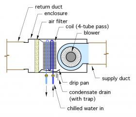
The main components inside an air handler are a water-to-air heat exchanger called a “coil,” and a blower. Other components include a removable filter and electrical controls. Any air handler intended to provide cooling must also have a condensate collection pan, which leads to a drainage connection. Figure 4-16 shows a representation of a typical horizontal air handler.
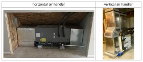
Small air handlers are often available with cabinets and internal components that allows them to be configured to connect to either horizontal or vertical ducting. Figure 4-17 shows an example of each.
The horizontal air handler shown in Figure 4-17 has a condensate collection pan under its internal coil. The trap assembly and 3/4-inch PVC piping seen near the bottom of the cabinet carries condensate away to a drainage pipe. The piping is pitched to allow for gravity drainage. The vertical air handler seen in Figure 4-17 is located in a basement that doesn’t have a floor drain. Condensate from the internal collection pan is routed to a condensate pump, which pushes it upward and outside the building above grade level.
Notice that the piping carrying chilled water to each of these fan-coils is fully wrapped with an elastomeric foam pipe insulation. This is critical to prevent surface condensation when the air handler is operating in cooling mode. All piping components, such as circulator volutes, valves, etc., should also be wrapped with an insulation that provides both thermal resistance and acts as a vapor barrier. Additional information on chilled-water cooling using air handlers and piping insulation is available at:
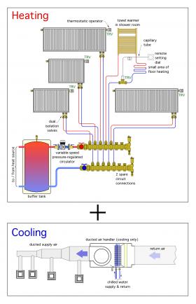
One system configuration that’s appropriate for residential and small commercial low-energy and net-zero buildings has multiple zones of heating combined with a single zone for cooling. The heating zones could be handled by multiple panel radiators, each equipped with thermostatic operators. Single-zone cooling is provide by a ducted air handler equipped with a chilled-water coil. Figure 4-18 shows two component assemblies based on this approach.
The heating assembly is called a “homerun” distribution system. Each of the 5 heated spaces served by this assembly has a small diameter (i.e., 1/2-inch) PEX tube for supply water and another for return water. All 5 homerun circuits begin and end at a manifold station that’s located in a mechanical room or within a recessed framing cavity. Heated water is supplied to the manifold station by a variable-speed pressure-regulated circulator. The high-efficiency motor in this circulator automatically adjusts its speed as the thermostatic operators on the panel radiators open, close or modulate the flow through their associated radiators.
To show versatility, one of the homerun circuits is routed to a towel warmer radiator that’s piped in series with a small area of floor heating. This would be appropriate in a bathroom with a tile floor. Flow through this circuit is also controlled by a thermostatic valve that would typically be located in an accessible framing cavity near the room, and connected by a small capillary tube to a wall-mounted adjusting knob that sets the comfort level in the room.
The buffer tank would be heated by the heat source (e.g., typically a heat pump). The thermal mass of this tank allows for very small heat dissipation rates at the heat emitters, when conditions warrant, without short cycling the heat source. The only electrical component in this heating sub-system is the circulator. Several examples of homerun distribution systems will be shown in section 5.
The single-zone cooling assembly uses a small air handler (either vertical or horizontal-mounted) combined with a ducted forced-air distribution system that supplies several ceiling or high-wall diffusers, each with a balancing damper. The chilled-water coil in the air handler cools and dehumidifies the air passing
through it. Condensate is collected by the pan under this coil and routed to a suitable drain. A horizontal air handler could be suspended from floor joists or placed on a small platform between trusses and within the building’s thermal envelope. A vertical air handler could be located in a small closet, again within the building’s thermal envelope.
INCORPORATING HEAT RECOVERY VENTILATION
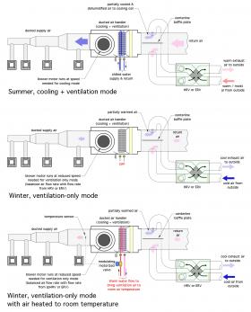
It is also possible to add a heat recovery ventilator (HRV), or an energy recovery ventilator (ERV) to the forced-air distribution system used for chilled-water cooling, as shown in Figure 4-19.
The supply and return ducts that lead back to the HRV or ERV are connected to the return air duct leading into the air handler. Ideally, these ducts are connected opposite from each other with a sheet metal baffle fixed along the centerline of the duct. This placement puts both ducts from the HRV or ERV at the same static pressure point on the return duct. This minimizes any tendency for induced air flow through the HRV or ERV if it is off, and the air handler is on. The centerline baffle prevents a “short circuit” of fresh incoming air back into the exhaust stream leading back to the HRV or ERV.
Operation of the HRV or ERV must be coordinated with the blower in the air handler. For example, in a “ventilation-only” mode, the blower in the air handler would operate at a relatively low speed sufficient to carry the required ventilation air flow rate, but significantly lower than the required flow rate when the air handler is providing cooling. During cooling mode operation, the blower speed would increase to provide an air flow of approximately 400 CFM per ton (12,000 Btu/hr) of cooling capacity. Modern air handlers have high-efficiency ECM motors with multiple-speed tappings that allow these different air flow rates to be achieved.
During winter, it would also be possible to pass a small flow of warm water through the air handler coil to bring the incoming ventilation air stream up to room temperature. The discharge air temperature from the air handler would be measured and used to modulate a motorized valve that regulates the warm water flow rate through the coil. This option would require additional piping design and components to enable warm water flow through the air handler’s coil. In cold climates, it may also require the air handler coil to operate with an antifreeze solution.
This approach eliminates the need to install a separate ducting system for the HRV or ERV.
BUFFER TANKS
There are several ways to zone a hydronic heating or cooling distribution system. The ease of doing so allows designers to create residential or light commercial systems that might have, for example, 3 to 8 zones. Even more zones are possible when individually controlled panel radiators are used, or for systems in larger commercial buildings. Zoning frequently creates situations where the rate of heat delivery to a zone is much lower than the rate of heat generation by the heat source. This is especially true when an “on/off” heat source is providing the heat.
For example, consider an air-to-water heat pump with a single-speed compressor that’s producing heat at a rate of 40,000 Btu/hr and imparting that heat to a hydronic distribution system. At the same time, only one of the building’s zones is calling for heat, and the rate of heat transfer to that zone is 3,000 Btu/hr. Assume the water in the heat emitter, the heat pump and the piping between them totals to 6 gallons. Also assume that the controller operating the heat pump allows a temperature differential of 15ºF between when the compressor is turned on and when it’s turned off. Under these conditions, the on-cycle time of the heat pump will only be 1.2 minutes! Such a short on-cycle time, repeated thousands of times per year, would shorten the life of the components in the heat pump, especially the compressor and the compressor contactor. This situation must be avoided.
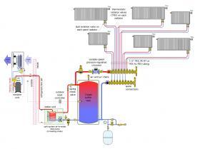
The common method of avoiding short-cycling in multi-zone hydronic systems is to incorporate additional water (and its associated thermal mass) into the system using an insulated buffer tank. Figure 4-20 shows an example of such a tank installed between an air-to-water heat pump and a zoned distribution system for a space heating-only application.
The buffer tank is piped in a “3-pipe” configuration. This allows the distribution system to draw the hottest available water, either directly from the heat pump circuit when the heat pump is operating, or from the upper connection on the buffer tank when the heat pump is off. Heated water leaving the heat pump doesn’t necessarily pass through the buffer tank before flowing to the panel radiators. Return water enters the lower side connection on the buffer tank. This ensures that the thermal mass of the buffer tank is always “engaged” with the flow returning from the radiators, and flow returning to the heat pump.
A variable-speed pressure-regulated circulator provides flow to six panel radiators using a homerun distribution system. The latter consists of a manifold station and 6 circuits of 1/2-inch PEX tubing. Each radiator has an integral valve and is equipped with a thermostatic operator, allowing for independent heat output regulation. Other components in the system include a DIRTMAG® PRO dirt and magnetic particle separator on the flow inlet to the heat pump, and a DISCALAIR® air separator on the supply to the manifold station.
A spring-check valve prevents reverse thermosiphoning from the buffer tank through the heat pump when the latter is off. An outdoor reset controller continuously monitors the water temperature at the mid-height of the buffer tank. This controller turns the heat pump and its associated circulator on and off as necessary to keep the average water temperature in the tank close to the target value calculated by the outdoor reset controller.
The system automatically begins operation when the outdoor temperature drops below some preset value known as the “warm weather shutdown temperature.” There are no electrical thermostats in this system. All room temperature control is regulated by the thermostatic operators on the panel radiators.
BUFFER TANK SIZING
The size of the buffer tank can be calculated based on the desired on-cycle time of the heat pump, the heat pump’s rated heating capacity, and the change in buffer tank temperature during the on-cycle. Use Formula 4-2.
Formula 4-2:
$$ V = {(q_{hp})t \over 500(\Delta T)} $$
Where:
$V$ = minimum volume of buffer tank (gallons)
$q_{hp}$ = rated heat output of heat pump (Btu/hr)
$t$ = length of desired on-cycle (minutes)
$\Delta T$ = temperature swing in buffer tank during on-cycle (ºF)
For example, assume the minimum desired on-cycle time is 10 minutes, and the desired temperature change in the buffer tank during that on-cycle is 15ºF. Determine the minimum buffer tank volume assuming the heat pump’s rated output is 36,000 Btu/hr. Just put the given values into Formula 4-2 and calculate:
$$ V = {(q_{hp})t \over 500(\Delta T)} = {(36,000)10 \over 500(15)} = 48gallons$$
Larger buffer tanks would allow either longer on-cycles, smaller values of $\Delta T$, or some combination of both. Likewise, small buffer tanks would result in shorter on-cycles, assuming the same desired tank temperature swing ($\Delta T$).
BUFFER TANKS & VARIABLE-CAPACITY HEAT PUMPS
Several air-to-water and water-to-water heat pumps are now available with variable-speed (“inverter driven”) compressors. These heat pumps can reduce their output down to 30-40 percent of their rated output. If the heating requirement of the smallest zone in the system is approximately the same as the minimum output of the heat pump, one could argue against the need for a buffer tank. However, in systems with several small zones, such as individually controlled panel radiators in each room, a buffer tank should still be used in heating mode operation.
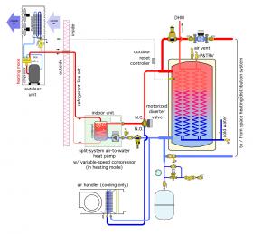
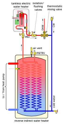
When multiple zones of heating are combined with a single cooling zone, and the system is supplied by a variable-capacity heat pump, it is possible to use a buffer tank in heating mode, but not in cooling mode. This combination allows the buffer tank to be maintained at an elevated temperature year-round to supply preheating, or possibly all the heating required for domestic hot water. Figure 4-21 shows one possible system configuration.
This system uses a “reverse” indirect water heater as a buffer tank. The heat pump maintains the water temperature in the shell of this tank between some upper and lower temperature limits, such as 110 and 130ºF. Domestic cold water passes upward through multiple copper coils inside the tank whenever domestic hot water is drawn from a fixture. That water is either partially heated or fully heated depending on the temperature of the water in the tank shell, the flow rate through the internal coils, and the desired domestic hot-water delivery temperature.
In cases where the domestic water is only partially heated as it passes through the coils, it’s possible to include an electric tank-type or on-demand water heater. Figure 4-22 shows piping for the latter.
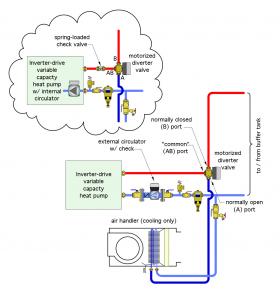
The water leaving the heat pump in Figure 4-21 enters the common port of a motorized diverter valve. This valve is energized when the heat pump operates in heating mode, allowing flow from the common port to the normally closed port, and onward to the buffer tank. When the heat pump is off, the diverter valve is off, and the normally closed port is closed. This prevents reverse thermosiphon flow from the buffer tank through the heat pump. It also prevents flow returning from the space-heating load from flowing through the heat pump when it is off.
The diverter valve should be selected with a flow coefficient (Cv value) approximately equal to the design flow rate through the heat pump. This limits the pressure drop through the valve to approximately 1 psi and reduces circulator power requirements.
Some air-to-water and water-to-water heat pumps are supplied with an internal circulator, and some require an external circulator. Figure 4-23 shows pipe detailing for both cases. The spring-loaded check valve in the external circulator, or as a separate component when an circulator is present inside the heat pump, provides a slight forward opening resistance to prevent flow migration through the chilled-water air handler when the heat pump and circulator are off.
A DIRTMAG® PRO separator is installed on the pipe leading into the heat pump. This location is also upstream of the heat pump’s circulator (whether internal or external). The DIRTMAG® PRO separator helps prevent dirt or ferrous metal particles from entering either the circulator or the heat pump’s heat exchanger, and thus helps maintain peak performance and reliability.
The system configuration shown in Figure 4-21, and in subsequent details shown in Figures 4-22 and 4-23, uses a variable-capacity (“inverter-driven”) heat pump. The internal controls for this type of heat pump typically allow compressor speed to be referenced to a user-set outlet water temperature in both heating and cooling mode.
When the heat pump is used to maintain the buffer tank within some range of temperature suitable for space heating and domestic water heating, it should be turned on and off based on the buffer tank temperature, rather than the outlet temperature from the heat pump. This typically requires an external controller that can open and close a set of electrical contacts based on either a setpoint temperature and associated differential, or on outdoor reset control.
An example of setpoint control would be as follows:
Heat pump = ON when tank sensor temperature drops to 100ºF or lower.
Heat pump = OFF when tank sensor temperature increases to 125ºF or higher.
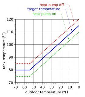
An example of outdoor reset control, with specific settings, is shown in Figure 4-24.
With outdoor reset, the heat pump is turned on when the sensor in the tank drops to the temperature shown on the dashed green line in Figure 4-24. The heat pump continues to run until the sensor reaches the temperature on the dashed red line. Outdoor reset controllers can be adjusted to change the slope of these lines, the temperature differential between the “on” and “off” lines, the minimum supply water temperature setting, and in some cases, additional settings. This allows wide flexibility in how the temperature of the buffer tank is regulated.
Reducing the tank temperature as the outdoor temperature increases allows the heat pump to operate at higher COP. This is ideal when the system only provides space heating. However, in systems that supply both space heating and domestic hot water, this control action decreases the temperature to which domestic water can be heated by the heat pump, especial during mild weather. This can be modeled using specific space heating and DHW load information, heat pump performance information, and climate data.
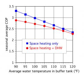
Figure 4-25 shows the simulated seasonal performance of an air-to-water heat pump based on supplying just space heating (blue line), or both space heating and domestic hot water (red line). Any temperature boost needed to ensure a DHW delivery temperature of 120ºF is assumed to be provided by electric resistance heating. Figure 4-24 plots seasonal average COP of the system versus the average temperature at which the buffer tank is maintained by the heat pump (e.g., based on setpoint control, not outdoor reset control). In this graph, the seasonal COP is for the entire system, including energy supplied to supplemental electric heating elements.
The simulations used to produce Figure 4-25 were based on a modern low-ambient air-to-water heat pump operating in a (6,700ºF•day) winter climate with a 60-gallon per day domestic water load heated from 50 to 120ºF. The upper (blue) curve shows significant improvements in seasonal average COP as the average water temperature in the buffer tank is reduced. This demonstrates the previously discussed advantages of using heat emitters that can operate at low water temperatures.
However, when the domestic water-heating load is factored in, the seasonal COPs are lower, especially when the average buffer tank temperature is lower. This happens because of increased use of electric resistance heating to ensure a DHW delivery temperature of 120ºF under all conditions. If the heat pump is only used for space heating, and all domestic hot water is provided by electric resistance heating, the simulated seasonal average COP for the system was 2.57.
When the buffer tank temperature is maintained based on outdoor reset control, heat from the buffer is used to preheat domestic water, and all supplemental heat to bring the DHW delivery temperature to 120ºF is provided by electric resistance heating, the system’s simulated seasonal COP was 2.82.
COOLING MODE CONTROL
The use of a variable-capacity heat pump, and a system configured as shown in figure 4-21, eliminates the need for the buffer tank to store chilled water during cooling mode operation. When the heat pump is operating in cooling mode, its compressor speed is varied to maintain a set leaving-water temperature (typically in the range of 45 to 55ºF). This allows the heat pump cooling capacity to track the cooling capacity of the chilled-water air handler. However, the air handler should be selected with a cooling capacity that is not lower than the minimum cooling capacity of the heat pump. For example, if the minimum cooling capacity of the heat pump is 22,000 Btu/hr when supplying chilled water at 45ºF and receiving return water at 55ºF, the air handler should also be able to absorb 22,000 Btu/hr when operating at the average water temperature of 50ºF (e.g., 45ºF in/55ºF out).
Whenever a heat pump (geothermal or air-to-water) can provide year-round domestic hot water as well as cooling, system controls must set a priority as to which load the heat pump services at times when both loads are simultaneously calling for operation. The most common scenario is to prioritize domestic water heating over cooling. This is based on the likelihood that the “call” for domestic water heating can be satisfied quickly (perhaps 5-10 minutes) during warm weather when the cooling load is active. Once the tank that provides domestic hot water (e.g., the buffer tank in figure 4-21) has reached a set temperature limit, the heat pump turns off, goes into a typical 3-5 minute time delay to allow for refrigerant pressures to equalize, then resumes cooling mode operation.
Given the loads and thermal mass associated with a typical low-energy or net-zero home, this method of priority control is generally acceptable. If the situation “insists” on simultaneous cooling and domestic water heating (e.g,, without prioritizing either load), a separate chilled-water buffer tank can be used, albeit at significantly higher cost and complexity.

