This section describes the optimal design and installation criteria for HPWHs.
New Construction Installations
Imagine that an architect, engineer and installer coordinated their efforts to construct a building with a HPWH in mind, as if it were a priority for integrated design. In a new construction setting, there would be fewer constraints when determining the size and location for infrastructure such as water service entrances, electrical panel placement, floor drain locations, size of the mechanical room and communication subsystems.
Under such ideal conditions, what would the design and installation team do to set up the HPWH for the best performance? This section discusses several considerations.
Water Heater Location
One early consideration in the design process is the physical location of the heat pump and storage tank. In new construction, an ideal location would be a mechanical space with good access to equipment that is in close proximity to the loads supplied by that equipment.
In moderate climates, a portion of a home’s garage space is often reserved for mechanical equipment, including the water heater. Garages provide convenient access for service and eventual replacement of water heaters. They also have lower potential for damage should a leak develop. Many garages have floor drains. Garages are also common points of entry for water and electrical services. The concrete floors in most garages can easily support the weight of residual water heaters, and when necessary, can be designed to handle much higher loads associated with large or multiple thermal storage tanks.
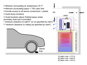
The mechanical space should allow for routine equipment service. HPWHs require service clearances for all tank connections, electrical access points, air filters, controls and refrigeration system components. Water heater manufacturers typically specify a minimum space requirement to install and service their equipment.
Fuel type can also dictate location. Gas water heaters require access to a gas service line and the ability to vent the products of combustion. Gas water heaters also are constrained by the maximum allowed length for vent piping. Nearly all codes require gas-fired water heaters that are located in garages to be on elevated platforms to prevent contact with gasoline or other fuels that might be spilled on floors.
Electric-resistance water heaters and HPWHs do not have the constraints associated with fuel supply and venting for gas-fired water heaters. They have an installation advantage in that they can often be located in relatively small closets or under sink vanities.
HPWHs need more space based on their airflow requirements. This is a major prerequisite for proper performance. If a HPWH is installed in the same space that would have been used for a similar-sized electric-resistance water heater, it could drastically limit performance.
An ideal location for a HPWH would be in the middle of a large interior space that maintains itself at or close to normal indoor temperatures. However, this is seldom possible because building space is expensive, and most occupants would much rather locate mechanical equipment in the smallest and least usable space within a building.
In many cases, water heaters are placed in minimally heated mechanical spaces that are separated from occupied spaces. These locations minimize noise transmission to occupied spaces and keep the equipment out of sight. Most HPWHs can be so located, provided that adequate airflow and surrounding air temperatures are ensured.
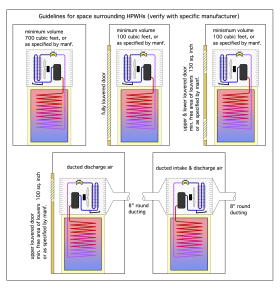
There are ways to provide for adequate airflow, while still partially enclosing the HPWH. Common options for self-contained residential HPWHs include the following:
- A large space having a minimum volume determined by HPWH size and manufacturer, with unobstructed airflow to the unit.
- A closet installation with a fully louvered door or a combination of upper/lower louvers, per manufacturer requirements.
- Inlet/outlet ducting to another space or outside, similar to a gas appliance.
Source of Absorbed Heat
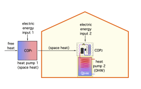
There are situations in which a HPWH placed in a conditioned space absorbs heat supplied by a furnace, boiler or heat pump used to heat that space. Effectively, the space heating system is providing most (or all) of the heat absorbed by the HPWH. While the wire-to-water efficiency of the HPWH might be excellent based on absorbing “surplus” heat not specifically generated for space heating, the net efficiency of using a HPWH decreases when absorbing heat generated by another device for space heating.
Examples of “surplus” heat include low-grade heat in outdoor air, excess solar heat gains inside a building, low-grade heat in an unconditioned basement or garage, or heat generated by equipment or processes in a commercial building. These sources of heat are a byproduct of how the building is configured or used, rather than heat intentionally produced by the building’s heating system.
Heat pump 1 is absorbing free heat from outside the building, combining it with heat derived from electricity, and sending that heat inside the building. Heat pump 2 is a HPWH. It absorbs heat that was placed inside the building from heat pump 1, combines it with more electrical energy, and sends combined energy into domestic water within the tank.
The net COP of this cascading heat pump system can be determined:
Formula 4-1
$$ COP_{net} = \color{blue}{{ \Bigl({COP_1 \over COP_1-1} \Bigl) \Bigl( {COP_2 \over COP_2-1} \Bigl)} \over \color{red}{{ \bigg[} \color{blue}{ \Bigl({COP_1 \over COP_1-1} \Bigl) \Bigl({COP_2 \over COP_2-1} \Bigl) -\color{red}{1}}} \color{red}{\bigg]}} $$
Where:
COP net = the overall COP of the two cascaded heat pumps
COP 1 = the COP of the space heating heat pump (must be > 1.0)
COP 2 = the COP of the heat pump water heater (must be > 1.0)
Note: To use this formula, both COP 1 and COP 2 must be > 1.0
For example, if a heat pump provides space heating to a building while operating at a COP of 4.0, and a heat pump water heater within that building only absorbed heat produced by the space heating heat pump while operating at a COP of 3.0, the net COP, defined as the heat added to the domestic water divided by the total electrical input to enable that heat placement, would be:
$$ COP_{net} = {\color{blue}{{ \Bigl({COP_1 \over COP_1-1} \Bigl) \Bigl( {COP_2 \over COP_2-1} \Bigl)}} \over \color{red}{{ \bigg[} \color{blue}{ \Bigl({COP_1 \over COP_1-1} \Bigl) \Bigl({COP_2 \over COP_2-1} \Bigl) -\color{red}{1}}} \color{red}{\bigg]}} = {\color{blue}{{ \Bigl({4 \over 4 - 1} \Bigl) \Bigl( {3 \over 3-1} \Bigl)}} \over \color{red}{{ \bigg[} {\color{blue}{ \Bigl({4 \over 4-1} \Bigl) \Bigl({3 \over 3-1} \Bigl)} -\color{red}{1}}} \color{red}{\bigg]}} {\color{black}=} {2 \over 2-{\color{red}1}} = 2.0 $$
A net COP of 2.0 means that for every two units of heat delivered to the domestic water, one was absorbed from a “free” source, and the other came as electric heating. Although this net COP is still double the COP of any form of electric-resistance heating (e.g., COP = 1.0), it is far lower than the rated COP of the heat pump water heater operating under the assumed condition of absorbing “free” surplus heat.
In most buildings, there will be times when the heat absorbed by the heat pump water heater is indeed surplus heat, and thus the long-term net COP will likely be higher than the above calculation implies. Still, the concept of “cascading heat pumps” shown in the previous example demonstrates that placing a HPWH within the heated thermal envelope of a low-energy or net-zero building, where the majority of the heat it absorbs is present due to operation of a space heating heat pump, doesn’t yield the savings often expected for HPWHs. In such cases, it could be more efficient to configure a domestic water heating subsystem as an ancillary load to the space heating heat pump. Section 5 shows some options for such configurations.
HPWHs always cool the space around them. This must be considered if the space is intended for normal human occupancy. A HPWH located close to an office or living area may cool that space to uncomfortable temperatures, especially during cold weather. Conversely, a HPWH can also create beneficial cooling and dehumidification of spaces that otherwise may be too warm or damp.
Noise is another placement consideration. All water heaters make some noise, and those sounds are perceived differently among occupants. For some, the clicks of a relay in an electric water heater might be annoying, while others may dislike the drone of a HPWH fan or gas appliance blower. Whenever possible, it is best to avoid placing any mechanical equipment, including HPWHs, adjacent to bedrooms, offices or other spaces that are intended to remain quiet. Many hours of design and installation labor can be required to relocate or otherwise address mechanical equipment after it has been installed without regard to the sound it creates, which often leads to complaints from occupants. The ability to duct the airflow required by HPWHs to and from locations away from occupied spaces can help alleviate thermal discomfort and noise issues.
Cold Climate Considerations
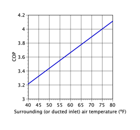
The coefficient of performance of a HPHW located in a cold garage or unconditioned mechanical space will be lower than if the same unit was located in a warmer area, such as a server room. At times of high domestic hot water demand, some HPWHs will also activate their electric-resistance heating elements to ensure adequate hot water delivery. This further decreases average efficiency. However, even at lower COP operating conditions, the HPHW uses significantly less electrical energy in comparison to a standard electric-resistance water heater.
It is also important to avoid installation locations where the water in piping leading to or from a HPWH could potentially freeze, especially during a prolonged power failure.
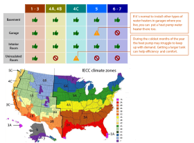
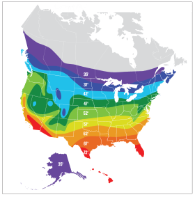
The Northwest Energy Efficiency Alliance (NEEA) provides guidance for HPWH installation locations, related to International Energy Conservation Code (IECC) climate zones across the U.S. The map in Figure 4-5 is useful to identify installation location possibilities and should be used in conjunction with HPWH manufacturer guidelines and local building codes.
Condensate Management
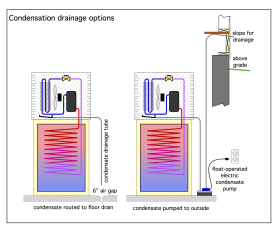
All HPWHs create condensate. It forms whenever the temperature of their evaporator coil drops below the dewpoint of the air passing across it. The condensate is not acidic, as is the condensate from a fossil fuel boiler. There is no need for a condensate neutralizer. However, the condensate must be routed to a suitable drain.
A floor drain in reasonable proximity to the HPWH is ideal. If a floor drain is not available, a small automatically operated condensate pump, such as used for residential air conditioning systems, can be used to route the condensate to another drain or outside the building. In the latter case, the condensate drain tube should end above grade and be sloped to avoid freezing in winter.
Electrical Power Supply
In new construction, planning to supply a HPWH with 240V power provides the most flexibility for equipment selection. While 120V HPWHs are available, they are best suited for retrofits, or situations where 240V power is not available or would be costly to supply. The use of 240V also reduces amperage and wire size. Larger commercial HPWHs generally require 3-phase power.
Locating the HWHP relatively close to a building’s electrical service panel, or a suitable sub-panel, reduces installation cost. The wire type and size used to supply the HPWH is generally specified by its manufacturer. All electrical materials and methods must also conform to local codes.
Tank Size
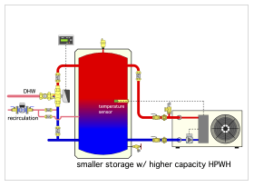
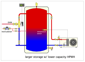
The volume of the storage tank in a HPWH is an important selection consideration. Larger storage volumes typically increase the amount of hot water the unit can deliver, based on the unit’s first hour rating. One downside to a larger tank is increased standby heat losses, which increase cost of operation without providing a benefit for building occupants.
Additionally, larger storage can increase the installed cost of the system. The balance between ideal water storage volume and heat pump output will vary by project. In Figure 4-7a, a system is designed with a larger heat pump and minimal storage. In Figure 4-7b, a system is sized with larger storage but a smaller HPWH. Both are acceptable designs. Consult with heat pump manufacturers for specific sizing guidance.
Storage Temperature and Point-of-Distribution Mixing Valves
All HPWHs have an adjustable water temperature setting. Increasing the storage temperature of a water heater increases its ability to deliver hot water to the building. It may also allow for a smaller tank. In some installations, the minimum storage tank temperature may also be mandated based on avoiding Legionella bacteria growth.
Point-of-distribution mixing valves are highly recommended whenever the temperature setting of the water heater is above 120ºF, or higher than otherwise allowed by code or other applicable regulations.
Two different types of mixing valves can be used in systems with elevated storage temperatures. Point-of-distribution (POD) mixing valves listed to ASSE 1017 are designed to deliver consistent water temperatures to the building's plumbing system by mixing hot and cold water. These devices are designed for high flow rates. They are not scald protection devices. Point-of-use (POU) mixing valves listed to ASSE 1070 are designed to prevent scalding at the fixtures.
Point-of-distribution mixing valves are a useful, adjustable part of a HPWH system. It is easier and typically less expensive to add a POD mixing valve, or adjust the temperature setting of such a valve, than to install a larger HPWH, especially if an electrical service upgrade is required for the latter.
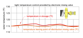
Point-of-distribution mixing valves allow the tank temperature to be set higher or for the tank temperature to fluctuate while maintaining a consistent and safe outlet temperature.
Here are three of the most common design options for consideration:
- Baseline example, fixed temperature setpoint. No point-of-distribution mixing valve.
- Elevated fixed setpoint. Point-of-distribution mixing valve is added to lower the outlet temperature, effectively adding heat storage capacity without increasing the size of the tank.
- Variable setpoint. Scheduled to avoid peak utility rates or coordinate with real-time utility information. A point-of-distribution mixing valve is added to lower the mixed outlet temperature, effectively adding energy storage capacity without increasing the size of the tank.
Design option 1 is typical in many water heater installations, especially new construction projects. A simple aquastat or tank sensor calls for heat when the water temperature in the tanks drops slightly. When the tank rises slightly above the setpoint temperature, the call for heat ends.
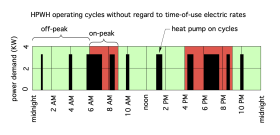
The temperature of water delivered to the building fluctuates slightly, within the temperature differential of these on/off cycles. Often, the differential is small and remains unnoticed by building occupants. No point-of-distribution mixing valve is used, but point-of-use ASSE 1070 may still be recommended (or required) by local codes or regulations. Figure 4-8 shows a conceptual cycling pattern for the HPWH.
The mathematical area of the black rectangles represents electrical energy input to the HPWH. Notice that much of the energy input occurs during peak electrical rate periods. The length of the on-cycle is determined primarily by the demand for hot water at fixtures.
An advantage of this control method is that it is simple and requires the minimum amount of components. A disadvantage is that it does not take advantage of time-of-use utility rates. Based on typical residential usage, most of the electrical energy used by a HPWH falls within the peak time-of-use utility rate windows. For utilities offering time-of-use electrical rates, the cost of electrical energy supplied during peak demand periods is often substantially higher than during off-peak times.
This type of loading is also a concern for utilities that are trying to decarbonize their energy offerings. For example, if all the gas-fired water heaters were switched to HPWH systems operating primarily during peak demand times, utilities would face major overloading, possibly leading to brownouts or other large-scale grid reliability issues.
Design option 2 adds a point-of-distribution mixing valve between the HPWH hot water outlet and the domestic hot water fixtures. The tank water is stored at a higher temperature than the baseline design option 1. An advantage of this scenario is that the higher storage temperature increases the tank's hot water delivery capacity without increasing tank size. The mixing valve provides a safe and consistent temperature to the fixtures throughout the day. A disadvantage is that the COP of the HPWH is slightly reduced when operating at higher water temperatures.
This is advantageous because the storage temperature does not necessarily have to be higher than the desired hot water delivery temperature. During periods of heavy DHW demand, this approach can maintain a consistent delivery temperature while extracting more heat from the tank.
Operating the HPWH at Higher Storage Temperature
How does the warmer storage temperature boost the effective hot water delivery capacity of the system? As an example, consider a project being designed for Atlanta, Georgia.
Start by determining the average groundwater temperature from the map in Figure 4-10.
For Atlanta, the average groundwater temperature is 62ºF. Assume that this is the cold-water temperature supplied to the water heater. The heat stored in a tank-style water heater can be determined using Formula 4-2a.
Formula 4-2a:
$$ H=8.33(v)(T_s-T_c) $$
Where:
H = heat stored in tank water (Btu)
8.33 = Btus required to raise 1 gallon of water 1ºF
V = tank volume (gallons)
Ts = average temperature of stored hot water (ºF)
Tc = cold-water inlet temperature (ºF)
Consider a 60-gallon tank maintained at an average temperature of 120ºF. The heat stored in this tank’s water would be:
$$ H_{120}=8.33(60)(120-62)=28,988 Btu $$
If the average storage temperature was increased from 120ºF to 130ºF, the heat stored in the same tank would be:
$$ H_{130}=8.33(60)(\color{red}{130} \color{black}-62)=33,986 Btu $$
The percentage increase in stored heat would be:
$$ {H_{130} \over H_{120}} = {33,986 Btu \over 28,988Btu} =1.172\approx17\% \ increase $$
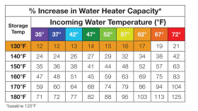
This increase can be approximated using the chart in Figure 4-11a.
Formula 4-3:
$$ {H_s \over H_b} = {(T_{s}-T_{c}) \over (T_{b}-T_{c})} $$
Where:
Ts = average storage temperature (ºF)
Tb = baseline storage temperature (ºF)
Tc = cold-water inlet temperature (ºF)
For example, assuming the same 62ºF cold-water temperature, the ratio of heat stored in a tank with an average water temperature of 140ºF, relative to a baseline average storage temperature of 120ºF, would be:
$$ {H_s \over H_b} = {(T_s-T_c) \over (T_b-T_c)} = {(140-62) \over (120-62)}=1.345 \approx 34.5\% \ increase $$
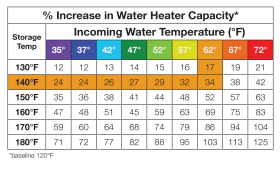
This increase could also be approximated using the chart in Figure 4-11b.
If the temperature were increased to 140°F, it would add 34% to the effective capacity. This would essentially make a 60-gallon water heater, storing water at 140°F, deliver the same amount of hot water in a parallel drawdown as an 80-gallon tank storing water at 120°F. The space-saving and cost-reducing potentials of this approach are significant. It also can allow for better demand response scenarios with electrical rates.
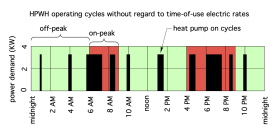
In design option 3, the setpoint of the tank changes depending on the time-of-use rates. Essentially, the tank is being used as a rechargeable thermal battery. It is “charged" with extra heat during “off-peak" periods of low electrical demand, with the intent of delivering the stored thermal energy during “on-peak" periods, and thus reducing the load on utilities during periods of high electrical demand. It's analogous to eating a big meal before leaving the house to minimize the amount of expensive vending machine snacks required before lunch.
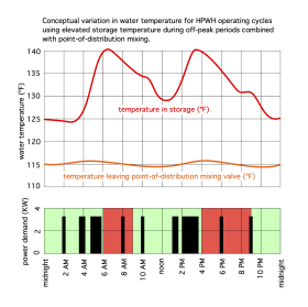
Figure 4-12 shows the concept. The mathematical area of the black rectangles represent the electrical energy supplied to the HPWH. Notice that the majority of this energy is supplied during the off-peak periods (approximately 85% of the total daily energy). The width of the rectangles increases, indicating longer heat pump on-cycles, especially ahead of the oncoming on-peak periods. This “packs” more heat into the storage tank.
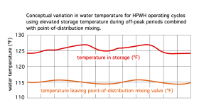
Figure 4-13 overlays the HPWH cycles with the conceptual temperatures of stored water and the hot water delivered to the fixture through a point-of-distribution mixing valve. An ASSE 1017 point-of-distribution mixing valve allows for consistent water delivery even when the tank is at higher temperatures. The cycle scheduling is controlled through an automated communication protocol with the electrical utility. The goal is to minimize electrical demand during on-peak times. This has the combined effect of reducing operating cost to the building owner, while also benefiting utility load management efforts.
The downside of storing water at an elevated temperature relates to maintenance, standby heat losses and the COP of the HPWH. The higher the temperature at which water is stored, the faster the scale will accumulate on heat exchangers and DHW components like thermostatic point-of-distribution mixing valves. Elevated temperatures also lead to faster galvanic corrosion, making anodic protection more vital. Higher storage temperatures increase standby heat loss from the tank and decrease the COP of the heat pump water heater.
As an alternative to external point-of-distribution mixing valves, water heater manufacturers can design their equipment with ASSE 1082 or 1084 compliant technologies to limit the point-of-distribution temperature. These technologies can be used in place of an ASSE 1017 point-of-distribution mixing valve. ASSE 1070 point-of-use mixing valves could still be required, depending on the jurisdiction.
For more information on mixing valve applications, point-of-use or point-of-distribution valves, refer to
Point-Of-Use Mixing Valves
ASSE 1070 valves are temperature-limiting devices designed to protect end-users from hot water scalding. They are also designed to prevent the flow of water from the mixed water outlet in the event of the failure of hot or cold supply. The size of the valve is generally smaller than a point-of-distribution valve because it is required to stop the flow of hot water quickly. Unlike a point-of-distribution mixing valve, the point-of-use valves are designed to protect a single fixture or a small group of fixtures.
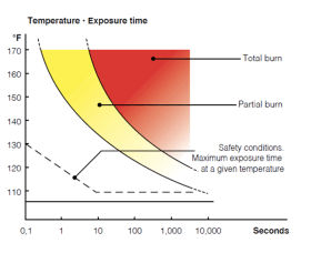
The maximum allowable hot water distribution temperature varies from one jurisdiction to another based on plumbing codes or other regulations. Occupant safety is always the primary concern upon which these codes or regulations are based. Scalding can occur quickly, as shown in Figure 4-14.
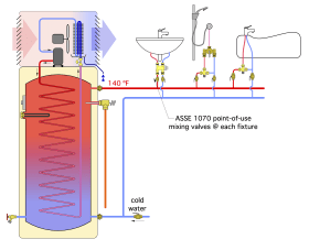
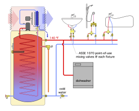
In some HPWH applications, a point-of-distribution mixing valve is not used. The temperature of the stored water may be elevated above a desired (or mandated) maximum delivery temperature. In these situations, point-of-use mixing valves should be used at each fixture or small grouping of fixtures, as shown in Figure 4-15a.
Domestic Hot Water Recirculation
In an ideal domestic hot water delivery system, heated water emerges from a faucet the moment it is opened. There would be no wait for cooler water to be purged from the piping ahead of heated water delivery. This desirable condition can be closely approximated through use of a recirculating domestic hot water delivery system.
There is an important balance to establish in recirculating domestic hot water systems: minimizing wait times for hot water at the fixtures while not wasting energy in the recirculation loop. In concept, DHW recirculation increases the total heat loss from the hot water delivery system. Holding the heated water in a well-insulated storage tank, rather than distribution piping, reduces heat loss and the excessive cycling of the water heater. However, omitting DHW recirculation systems may result in extended wait times for hot water at fixtures, which is undesirable and also leads to excessive water waste.
Poorly designed or inadequately insulated hot water recirculation systems can create unnecessary cycling of water heaters, thus wasting energy. This effect is potentially more noticeable in systems using HPWHs due to their reduced heating capacity/recovery rate relative to gas-fired water heaters. This is especially true during periods of high hot water demand or in systems with excessive heat loss from a recirculating piping loop.
In some situations, hot water recirculation to all fixtures is not justified. As an example, if a warehouse has a single mop sink located far from the water heater, a small, dedicated point-of- use water heater at the sink would save installation time and cost. It would also reduce energy losses compared to circulating hot water over long distances.
For more information on balancing valve applications for DHW recirculation, refer to
Retrofit Heat Pump Water Heater Installations
This section discusses factors that need to be considered when adding a heat pump water heater to an existing system.
Based on a mix of workforce development, new HPWH technologies, rebate programs, energy standard advancements and other factors, a 2022 Progress Report by the Advanced Water Heater Initiative projected 30% HPWH market share scenario by 2028. Retrofit application flexibility is key, because a majority of the water heater market is for the emergency replacement of failed water heaters.
While planning for the best-case new construction installation of a HPWH was discussed in the previous section, additional considerations need to be made for retrofit installations.
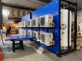
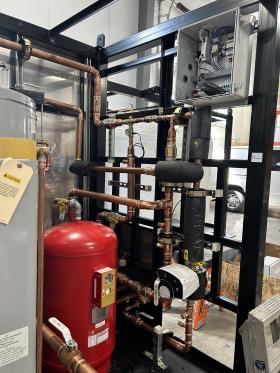
Every installation location is different. As is the case in all field-installed mechanical systems, some site conditions may be ideal, while others may be limiting. Prefabrication is an excellent option for commercial retrofit systems, as shown in Figures 4-16a,b.
Water Heater Location
In a retrofit, the location of the water heater is sometimes predetermined; however, a thorough assessment of the location needs to be made before replacement work begins. The basic requirements for airflow, electrical capacity, service clearances and condensate drainage need to be verified. If one or more of these prerequisites cannot be met with reasonable cost and complexity, it is better to use another type of water heater rather than compromise the performance of the HPWH. In scenarios where a HPWH is not utilized, there is still opportunity to update mixing valves, balancing valves and add insulation to improve the performance of the system.
In some residential installations, there is an opportunity to move the water heater from the original location to a new space. Often a garage in a residential application is a good fit for a relocation in a milder climate. However, the distribution piping and components might also need to be relocated, increasing installation cost. Always check the manufacturer installation manuals when determining acceptable locations.
Airflow
HPWHs need an adequate supply of air to operate at peak performance. In a retrofit application, this could mean “unboxing” the mechanical space. When replacing existing water heaters that were installed in closets or small mechanical spaces, verify the minimum volume of the space with the HPWH manufacturer’s requirements. If the minimum volume is not met, one possibility is to add louvers to the mechanical room doors. A few ideal locations for louvered doors would be in an adjacent exterior hallway/atrium that has solar gains from windows or in a computer server room that may have a high cooling load. A few undesirable location examples would be louvered doors connecting to bedrooms, offices or living spaces where occupants may be impacted by the cool air leaving the HPWH or by the sounds of the equipment.
Because it creates the potential for condensation, avoid ducting a HPWH system to an attic. A general recommendation is to terminate the ductwork outside the building envelope.
When replacing a gas water heater with a HPWH, there may be existing ductwork for supplying combustion air. That ducting may be reusable for a HPWH installation, depending on the diameter and total equivalent feet of the ductwork.
An advantage of using ducted outside air for a HPWH is that the absorbed heat is coming from outside the building envelope. This reduces the possibility of thermal discomfort near the equipment. A downside to outdoor ducting is the added installation time and cost. It is also important to consider that if only the exhaust air from the HPWH is ducted outside, a negative air pressure could be created in the space, drawing more outside air through the building envelope.
The main decision points for ducting outside air to the HPWH relate to climate. In a high alpine environment, the COP of the HPWH may be significantly lower if ~40°F air is the source of absorbed heat. Ducting supply air from the outdoors in a warm climate may lead to a higher COP, compared to absorbing heat from the cooler, conditioned air within the building.
Equipment service clearances should also be checked. Avoid installing HPWHs in areas that generate considerable dust (e.g. a basement woodshop). The dust will quickly accumulate on the filter screen. If the screen is not frequently cleaned, the performance of the heat pump will decrease due to reduced airflow. If the screen is removed, the dust will accumulate on the evaporator coil where it would be difficult or impossible to remove.
Installers should also ask owners about any issues related to their current water heater when considering a HPWH. For example, does the current system create objectionable noises or does it take a long time for hot water to reach certain fixtures when first used in the morning? These insights help guide placement of a replacement water heater in a way that minimizes or eliminates undesirable existing issues.
Condensate
Ideally, the condensate produced by a HPWH would flow by gravity through a pipe to a suitable drain. When this isn’t possible, one option is to install a condensate pump that would collect and expel any condensate produced by the HPWH. There may also be a possibility of connecting the condensate drainage tube from the HPWH to a condensate drainage pipe or pump that serves an existing air conditioning system or other type of heat pump.
Piping
Installers should examine the piping to an existing water heater to determine if improvements can be made at the same time as the water heater replacement. The issue of wasteful DHW recirculation piping in existing buildings will not be remedied by replacing the existing water heater with a HPWH. A poor DHW recirculation system may be revealed when a HPWH is installed, if not accounted for in the retrofit work. With any equipment upgrade, reassessing pipe insulation, mixing, balancing and other componentry is critical. Additionally, the cost and complexity of making changes to the hot water distribution system will often be lower if done at the same time the water heater is replaced.
The heat loss of an existing recirculation loop should also be evaluated to determine next steps in a retrofit. This is especially important with HPWHs because if the heat loss of the recirculation is similar to the output of the HPWH when in heat pump only mode (as opposed to hybrid mode, where electrical resistance heating is also operating), the heat pump might need to operate whenever the recirculation pump is on.
It is important to know the rate of heat loss from a recirculating DHW loop. The following example demonstrates that this is a relatively easy calculation.
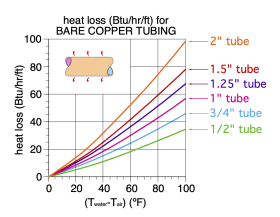
Assume that an existing recirculation loop operates at an average water temperature of 120ºF. The recirculation piping has a total length of 300 feet through an unconditioned crawl space where the air temperature is 55°F. The entire recirculation loop is piped with bare ¾" copper tubing. Figure 4-17 can be used to estimate the rate of heat loss from each foot of bare copper water tubing based on the difference in temperature between the water in the tubing and the surrounding air.
300 feet of ¾" bare copper tubing
Twater = 120°F
Tair = 55°F
T difference = 65°F
Heat loss = 27 Btu/hr/ft * 300 feet
Total heat loss = 8,100 Btu/h
Assume that the HPWH is properly sized for the design load and has a heat pump only mode heating capacity (e.g., without electrical backup heating) of 8,500 Btu/hr. In this example, the heat pump essentially provides temperature maintenance for the recirculation loop, while the backup electrical element would be needed to help carry the hot water fixture load. This will lower the net COP of the HPWH system since a significant portion of the water heating was done by the electric-resistance elements rather than the heat pump refrigeration system.
The opportunity for energy savings is wasted when much of the HPWH’s heat pump only mode output is required to offset heat loss in the recirculation loop. Reducing such losses when installing a HPWH increases cost but often yields a high return on investment.
For more information on balancing valve applications for DHW recirculation, refer to
Consider another retrofit example in which the recirculation loop ∆T is only 1°F. In this case, the domestic hot water recirculation pump is likely oversized. It is important to verify that the velocity of the recirculation piping isn’t above 5 feet per second with copper pipe, when carrying water up to 140°F. In systems with higher temperatures, consult the piping manufacturer to determine the velocity limit. In some cases, the target velocity may drop to 2-3 feet per second. If the flow velocity within the recirculation piping is high, there is a greater likelihood of developing pinhole leaks as the piping material erodes.
Balancing valves are helpful to equally distribute water through all branches of the domestic hot water system. The recirculation pump will bring water around the piping circuit through the path of least resistance. This can create high velocity through certain risers or laterals, which can lead to pinhole leaks. In the service sector, this is often blamed on an undersized recirculation pump. Upsizing the recirculation pump often exacerbates underlying balancing issues and increases the likelihood of pin-holing the piping material, without reducing the wait times for hot water at the fixtures.
120 VAC Heat Pump Water Heaters
The earliest HPWHs installed in North America required 240V electrical input. In buildings constructed with natural gas, propane or fuel oil as the intended fuel for domestic water heating, a 240V dedicated circuit would have to be added to supply these units.
However, some existing gas-fired water heaters, as well as oil-fired water heaters, may already be serviced by a dedicated 120V circuit. Recognizing this, some HPWH manufacturers have developed 120V models that could reuse this existing dedicated circuit. When possible, this reduces installation cost, especially in situations where a licensed electrician would have to be hired to install a new dedicated 240V circuit.
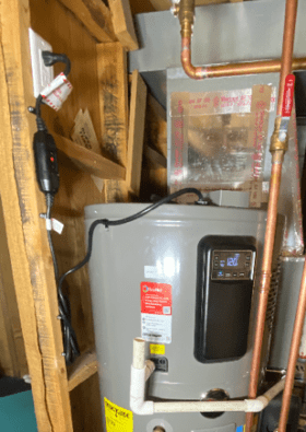
Some manufacturers also offer 120V HPWHs that can be plugged into a shared (rather than dedicated) 120V circuit. A retrofit example is shown in Figure 4-18.
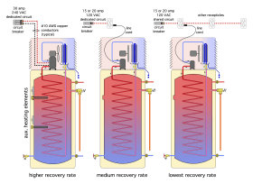
120V heat pump water heaters have lower recovery rates than 240V models. For example, one 50-gallon model designed for a dedicated 120V /15 amp circuit can provide 28 gallons per hour with a 60ºF temperature rise. A similar model with the same tank size, but intended to be used on a 120V /15 amp shared circuit can only provide 12 gallons per hour across the same temperature rise. This is due to a smaller compressor in the model designed for a shared circuit. Most HPWHs that are designed for 240V /30 amp dedicated circuits, and are equipped with auxiliary heating elements, can provide over 40 gallons per hour across the 60ºF temperature rise (see Figure 4-19).
Tank Size
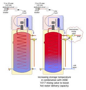
When replacing a gas-fired or electric-resistance water heater with a heat pump water heater, it’s important to compare the first hour DHW production ratings. It may be necessary to increase the volume of a HPWH to reasonably match the recovery rate of the existing water heater — especially if it’s a gas-fired unit. If a larger tank is selected to achieve the desired first hour rating, be sure there is ample space available — especially height — to accommodate it. When a larger tank is not possible, consider operating the HPWH at a slightly higher storage temperature, combined with an ASSE 1017 rated thermostatic mixing valve to increase the amount of hot water available during high demand periods, as illustrated in Figure 4-19.
Planning For Future Replacements
The water heaters available for the replacement of a 15-year-old unit are likely different from the original installation. As policy, energy standards and production methods change, so does the available stock of potential replacement water heaters. This has always been the case, it is not a new phenomenon with HPWHs. It is likely that at the end of the service life of the equipment being installed today, a direct replacement might not be available. To simplify the eventual replacement of a water heater, always install isolation and service valves between the water heater and the remainder of the domestic water system.


