Having discussed many aspects of distribution system design, it’s time to combine several details into systems. This section will present several such systems.
System #1
System #1: Baseboard system using manifold distribution + indirect domestic water heating
Fin-tube baseboard is one of the most common hydronic heat emitters used in North American hydronic systems. Traditionally, multiple fin-tube baseboards have been connected into a series circuit using rigid copper piping. In smaller houses, a single series loop has often been used. In larger houses, there may be two or more series loops based on zoning.
Although this traditional approach works, it carries the previously discussed limitations associated with series loop systems (e.g., temperature drop from one baseboard to the next, higher head loss, lack of room-by-room zoning). This approach was also developed when rigid copper tubing was typically the only practical piping material available for such systems.
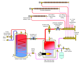
Today there are hardware selections available that can significantly improve both the installation and performance of traditional fin-tube baseboard heat emitters. The system shown in Figure 8-1 is one example. It retains fin-tube baseboard as the heat emitters, but changes the piping arrangement from series circuits to a homerun system.
Each baseboard is served by supply and return tubing made of flexible 1/2-inch PEX or PEX-AL-PEX tubing. This tubing is much easier and faster to install compared to rigid copper tubing, especially in retrofit applications.
All baseboard circuits are now in parallel and connected to a central manifold. Each baseboard will receive water at the same temperature. Parallel piping also allows the flow rate to each baseboard to be independently controlled. The use of thermostatic radiator valves on the supply side of each baseboard allows for room-by-room zoning.
The variable-speed pressure-regulated circulator is set for constant differential pressure mode and adjusted to provide sufficient differential so that design flow rates can be supplied to all six baseboards operating simultaneously. This circulator will automatically reduce its speed (and its electrical energy usage) as the thermostatic valves modulate to reduce or stop flow through each distribution circuit. The circulator is turned on whenever the temperature at a master thermostat drops below its setpoint. If none of the thermostatic radiator valves are open, the circulator drops into a “sleep” mode where power consumption is less than 10 watts. As a radiator valve begins to open, the circulator automatically senses the attempted drop in differential pressure and responds by increasing its speed.
A magnetic air/dirt separator is installed upstream of the variable-speed circulator. Its coalescing media will strip out and eject microbubbles from the system. The lower portion of the separator will capture both ferrous and non-ferrous particles before they can enter the circulator.
The indirect water heater is connected as a separate zone with its own circulator. Domestic water heating is controlled as a priority load. During a call for domestic water heating, the circulator supplying the manifold station is temporarily turned off. This allows the full heat output of the boiler to be directed to domestic water heating, ensuring the fastest possible recovery to the tank’s setpoint temperature. A 3-way thermostatic valve ensures that domestic water leaving the tank does not exceed a safe delivery temperature.
This system uses an oil-fired, cast iron, sectional boiler. Such boilers generally have sufficient thermal mass to stabilize heat delivery to a zoned distribution system, and thus a buffer tank is not needed.
System #2
System #2: Multiple water temperature system supplying panel radiators and radiant panels, in combination with “on-demand” domestic water heating.
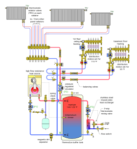
The versatility of hydronics makes it easy to build a distribution system that requires a range of water temperatures to supply different types of heat emitters. The system shown in Figure 8-2 allows for three simultaneous supply water temperatures. They range from a low of 95ºF for the basement floor heating circuits, to 120ºF for the panel radiators. Another area of radiant panel heating requires a supply water temperature of 110ºF.
All heat for the system comes from a low thermal mass modulating/condensing boiler.
A Caleffi ThermoCon buffer tank is used to protect this boiler from short cycling when minimal loads are present on the extensively zoned distribution system. The boiler fires to maintain the temperature at the mid-height sensor location between 120 and 140ºF. This allows the mod/ con boiler to operate in condensing mode most of the time. The buffer tank has been sized to allow the boiler to operate for a minimum of 10 minutes when there is no concurrent load on the system.
The buffer tank is piped in a “2-pipe” configuration. This reduces the flow velocity of heated water entering the upper sidewall connection of the tank when the distribution system is operating at the same time as the boiler. Reduced inlet flow velocity encourages better temperature stratification within the tank. The short and generously sized headers at points A and B also allow the tank to provide hydraulic separation between the boiler circulator (P1) and the variable-speed distribution circulator (P2).
A spring-loaded check valve near the upper tank header, as well as an internal spring-loaded check valve in the boiler circulator, prevent hot water in the tank from reverse thermosiphoning through the boiler circuit when the boiler is off.
A single pressure-regulated variable-speed circulator (P2) supplies flow to two Caleffi distribution stations, each set at an appropriate supply temperature for the radiant panel circuits they serve. This circulator also provides flow to a manifold station that supplies 4 panel radiators, which are piped as a homerun subsystem.
Zone valves open and close to determine which of the three load circuits receives hot water. The bypass built into each distribution station provides hydraulic separation between the variable-speed distribution circulator and the fixed-speed circulator in each distribution system. Each of the three load circuits is equipped with a flow-balancing valve. This allows the proper flow proportions to be set, assuming all three loads are operating simultaneously under design load conditions. The variable-speed pressure regulated circulator (P2) ramps its speed up or down as necessary to maintain approximately constant differential pressure between the supply and return headers.
Domestic water is heated “on demand” by the stainless steel heat exchanger seen to the right of the ThermoCon tank. Whenever there is a draw of hot water, a flow-activated switch turns on circulator (P3) to send hot water from the top of the ThermoCon tank through the primary side of the heat exchanger. Domestic cold water passes through the other side of the heat exchanger and absorbs heat. A 3-way thermostatic mixing valve provides anti-scald protection for the domestic hot water delivery. This configuration leverages the thermal mass of the ThermoCon tank to stabilize domestic hot water production, and eliminates the need for an indirect water heater. Because the top of the tank is always at or above 120ºF, domestic water is always available.
System #3
System #3: Space heat and domestic hot water supplied from a pellet-fueled boiler with an auxiliary boiler
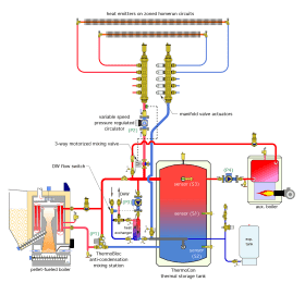
The system shown in Figure 8-3 uses a pellet-fueled boiler as the primary heating source, and an oil-fired boiler as the auxiliary heat source. For good thermal efficiency and low emissions, the pellet boiler is sized to 75% of the building’s design heating loss. This allows it to provide about 96% of the total seasonal space-heating energy needs, and helps prevent short cycling under partial loads.
The auxiliary boiler fires only when the pellet-fueled boiler is unable to keep pace with the total load on the system.
A Caleffi ThermoCon tank serves as the central thermal mass component of the system. It can accept heat from either boiler and deliver heat to both space-heating and domestic water-heating loads. The multiple connection ports on this tank allow for both piping connections and sensor placements that coordinate with the overall system control scheme.
The pellet-fueled boiler is turned on when storage sensor (S1) drops to 130ºF. It remains on until the lower tank sensor (S2) reaches 175ºF. This operating logic allows for long burn cycles and good thermal performance. The auxiliary boiler is fired only if sensor (S3) in the upper portion of the ThermoCon tank drops to or below 130ºF. Once fired, the auxiliary boiler remains on until the upper tank sensor (S3) reaches 140ºF. These temperatures are high enough that anti-condensation protection is not needed by the auxiliary boiler.
The pellet-fueled boiler is protected against sustained flue gas condensation by the ThermoBloc mixing station. This mixing station also creates flow between the pellet-fueled boiler and the header on the left side of the ThermoCon tank. If a power failure occurs, the ThermoBloc allows passive thermosiphon flow between the pellet-fueled boiler and ThermoCon tank. This safely dissipates residual heat from the boiler into the tank.
The ThermoCon tank is set up in a “2-pipe” configuration with short 2” pipe size headers at the upper and lower left side connections. This configuration allows the tank to absorb any surplus heat created by either heat source that is not being used by the loads. It also allows the tank to provide hydraulic separation between all the circulators.
Space heating is provided by multiple homerun circuits of 1/2” PEX or PEX-AL-PEX tubing routed from the manifold station to each of several fin-tube baseboard heat emitters. These emitters have been sized to deliver design load output at a supply water temperature of 130ºF. Flow to each heat emitter is controlled by manifold valve actuators on the return manifold.
A 3-way motorized mixing valve controls the water temperature suppled to the heat emitters. This valve is regulated based on outdoor reset control. It reduces what could be relatively high temperature (180+ºF) water from the thermal storage tank to a value that allows the heat emitters to supply the current heating load of the building.
Domestic water is heated “on demand” by the stainless steel heat exchanger seen to the left of the ThermoCon tank. Whenever there is a draw of hot water, the flow switch turns on circulator (P3) to send hot water from the top of the ThermoCon tank through the primary side of the heat exchanger. Domestic cold water passes through the other side of the heat exchanger and absorbs heat. A 3-way thermostatic mixing valve provides anti-scald protection for the domestic hot water delivery. This configuration leverages the thermal mass of the ThermoCon tank to stabilized domestic hot water production, and eliminates the need for an indirect water heater. Because the top of the tank is always at or above 130 ºF, domestic water can always be produced. If the pellet-fueled boiler is not operating, the upper portion of the ThermoCon tank is maintained at a minimum acceptable temper by the auxiliary boiler. This configuration also provides buffering for the auxiliary boiler to prevent short cycling.
System #4
System #4: Space Heating, cooling & DHW from air-to-water heat pump
Most hydronic heat pumps can provide heated water for space heating and domestic hot water production, as well as chilled water for cooling. The system shown in Figure 8-4 takes advantage of this ability to provide room by room zoned heating, two zones of cooling, and domestic water heating.
This system uses a 2-stage air-to-water heat pump. Heating or cooling capacity can be switched between 100 % of maximum rated output and 50% of that output. This is particularly important for the zoned cooling distribution system. If only only one air handler is operating, the cooling capacity of the heat pump can be reduced to prevent short cycling.
The heat pump is connected to an antifreeze protected circuit. In heating mode, heated antifreeze flows through a 3-way diverter valve to heat exchanger #1, where heat is transferred to water. This heat exchanger has been sized so that the approach temperature difference (e.g., the temperature difference between the incoming antifreeze solution and the leaving water) is only 5 ºF under full design heat transfer rate. Heated water is then routed to a generously sized header at the top left connection of the ThermoCon buffer tank. If one or more of the panel radiators is active, some of the heated water is routed to the load. The remainder goes into the buffer tank.
A variable speed pressure-regulated circulator, set for constant differential pressure mode, automatically adjusts speed based on the flow demands of the homerun distribution subsystem serving the panel radiators. Each radiator is equipped with a thermostatic radiator valve to allow room-by-room comfort control. Each radiator also has a dual isolation valve at its lower connections.
During heating mode operation, the temperature of the thermal storage tank is regulated based on outdoor reset control. Under design load conditions, the tank is heated to 125 ºF at the mid-height sensor. Under partial load conditions the temperature to which the tank is heated decreases with increasing outdoor temperature. The minimum tank temperature is set to 90 ºF. Reducing the tank temperature under partial load conditions allows the heat pump to achieve higher COPs and higher heating capacities.
The cooling subsystem is a 2-pipe direct return configuration. It connects “upstream” of heat exchanger #1. When the 3-way diverter valve is energized, all incoming chilled antifreeze is routed to the active air handler(s). The heat exchanger is not involved in cooling mode operation. This eliminates any thermal penalty, allowing for optimal cooling performance.
Flow through each air handler is controlled by a zone valve. Circulator (P1), which drives flow through the heat pump, also drives flow through the air handlers. A differential pressure bypass valve is installed at the end of the 2-pipe distribution system to prevent over-pressure when only one air handler is operating. A Caleffi FloCal valve is installed in the piping to each air handler. This valve ensures stable flow through each air handler regardless of the status of the other air handler. During cooling mode operation, the temperature of the antifreeze solution delivered to the air handlers varies between 40 and 60 ºF.
Domestic water is heated “on demand” by the stainless steel heat exchanger connected to the ThermoCon tank. Whenever there is a draw of hot water, a flow switch turns on circulator (P4) to send hot water from the top of the ThermoCon tank through the primary side of the heat exchanger. Domestic cold water passes through the other side of the heat exchanger and absorbs heat. The temperature of the domestic water leaving the heat exchanger depends on the temperature of the water in the upper portion of the buffer tank. In this system that temperature varies from a high of 125 ºF under design space heating load conditions, to a minimum of 90 ºF under partial space heating load. This implies that there will be times when the domestic water leaving the heat exchanger is only partially heated. Therefore, a thermostatically controlled electric tankless water heater is provided to “boost” the domestic water temperature to the value deemed necessary. A 3-way thermostatic mixing valve provides anti-scald protection for the domestic hot water delivery. This configuration leverages the thermal mass of the ThermoCon tank to stabilize domestic hot water production, and eliminates the need for a separate water heating tank.
The system’s controls are configured to allow the buffer tank to be heated, as a priority load, whenever the system is set for cooling mode operation, and the tank temperature drops to 120 ºF or less. This ensures that most of the heat delivered for domestic water heating will be sourced from the heat pump rather than from the tankless electric heater. If the tank drops to 120 ºF or less, any active cooling load is temporarily suspended while the tank temperature is increased to 130 ºF, after which cooling resumes.
System #5
System #5: Space Heating and DHw using mixed heat emitters
The system shown in Figure 8-5 is a modification of the system shown in Figure 8-1.
This system combines fin-tube convectors and panel radiators within a modified homerun system. The two fin-tube baseboards are individually supplied from the manifold station. Each is equipped with a thermostatic radiator valve to allow individual room temperature control.
Likewise, the panel radiator at the far right of the system is connected using a homerun distribution circuit and is regulated by a thermostatic radiator valve.
The three panel radiators at the top of the schematic are located in a remote area of the building, perhaps 75 feet away from the manifold station. They appear to be connected in a series circuit. However, each is equipped with an H-pattern bypass valve. This allows flow through each panel to be individually controlled. This series bypass arrangement was selected to reduce the amount of tubing that would otherwise be required to provide individual homerun circuits to each of these panel radiators.
Domestic water is heated by an indirect water heater operated as a priority load.


