The previous sections have discussed several preferred piping details for hydronic distribution systems. While it’s good to fill a designer’s toolbox with such details, it’s also good to create a “blacklist” of details that should be avoided. This section presents several such details, discusses the problem, and presents at least one way to correct each deficiency.
Common Hydronic Piping Errors
Error 1: Circulator located upstream of expansion tank
Discussion: This is a common error found in many existing hydronic systems. It stems partially from the traditional practice of installing a circulator on the return side of a boiler. This was usually done to reduce the size of shipping containers, rather than as a result of best hydronic design practice.
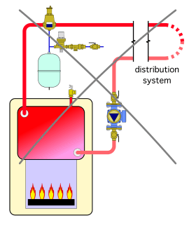
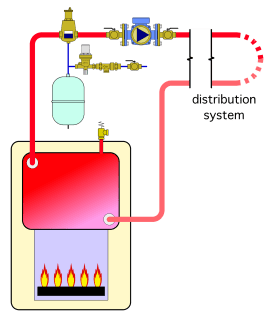
Another traditional practice was to attach the system’s expansion tank to the bottom of the air separator, which was located on the outlet side of the boiler, as shown in Figure 7-1a. This arrangement puts the point of no pressure change (PONPC) near the discharge of the circulator. This causes the pressure in most areas of the distribution system to drop when the circulator turns on. If the pressure at some point in the distribution system drops below atmospheric pressure, and if there are any components such as float-type air vents or valves with loose packings present at these locations, air can be sucked into the system each time the circulator runs.
This problem usually presents itself as the inability to rid the system of air. The system might be purged to a point where the service person believes air has been eliminated. However, the air problem reappears in a short time through the process described above.
Solution: Move the circulator so that its inlet port is close to the point of no pressure change (PONPC), as shown in Figure 7-1b.
Error 2: Routing total system flow through high flow resistance heat source
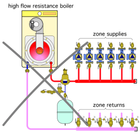
Discussion: There are several types of hydronic heat sources and chillers that have high flow resistance, especially in comparison to early generation boilers. A good example is a mod/con boiler with a compact heat exchanger. Another is a water-to-water heat pump with a coaxial heat exchanger. Problems arise when such devices are piped so that all system flow must pass through them, as shown in Figure 7-2a.
A high flow resistance heat source or chiller, piped as shown in Figure 7-2a, can significantly increase the flow resistance of the circuit in which it is located. If this higher flow resistance is not eliminated or otherwise compensated for through use of a more powerful circulator(s), the flow rate through the system will be much lower than anticipated. The result will be inadequate heat delivery, or in the case of a chilled-water system, inadequate cooling. The arrangement shown in Figure 7-2a also fails to provide hydraulic separation between the circulators.
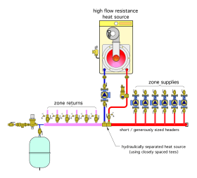
Solution: Install the high flow resistance heat source in a hydraulically separated circuit, such as shown in Figure 7-2b.
This system uses a dedicated boiler circulator in combination with a pair of closely spaced tees to hydraulically separate the high flow resistance heat source, and provide sufficient flow through it. This arrangement will not affect flow in the remainder of the distribution system. This same technique could be used for chillers.
Another option is to install a hydraulic separator between the heat source and distribution system, along with the dedicated circulator, as shown in Figure 7-2c. This option provides hydraulic separation, as well as high-performance air and dirt separation, for the system.
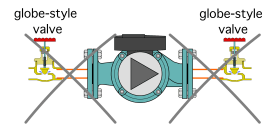
Error 3: Using high flow resistance valves for component isolation
Good practice advocates placing a means of isolating major components within a hydronic system. This includes boilers, circulator, heat exchangers and tanks. The valves used for isolating components need to provide a pressure-tight seal when closed. However,
they should also create very little head loss when they are open, which they should be over the vast majority of their service life.
The more head loss an open isolation valve creates, the more pumping power is required to maintain a given flow rate in the system. One could think of using higher flow resistance isolation valves as equivalent to keeping the brakes on a car slightly engaged at all times. Both are a needless waste of mechanical energy.
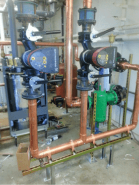
Solution: Several types of valves can provide acceptable service as isolation valves. These include gate valves, full-port ball valves and butterfly valves. The latter are typically used in flange-connected piping systems, as shown in Figure 7-3b.
Error 4: Lack of differential pressure control in systems using valve-based zoning
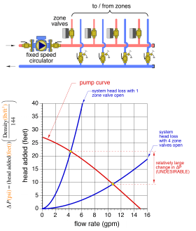
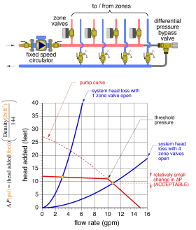
Discussion: Many hydronic systems use valve-based zoning. These include systems with electrically operated zone valves, manifold valve actuators or thermostatic radiator valves. The circulators in these systems are selected based on providing the necessary flow rate and corresponding head loss of the distribution system when all valves that control flow to the zones are open. When one or more zones turn off, and a fixed-speed circulator is providing flow, the differential pressure created by the circulator increases, as shown in Figure 7-4a.
The increased pressure differential between the supply and return headers causes the flow in the active zone circuits to increase. In some cases, this leads to flow noise, or even internal erosion of components if the flow velocities are excessive.
Solutions: The ideal system would maintain the same differential pressure between the supply and return headers regardless of the number of active zones. This can be closely approximated in two ways:
1. Use of a properly set differential pressure bypass valve
2. Use of a variable-speed circulator configured for constant differential pressure control
Figure 7-4b shows how a differential pressure bypass valve would be added to the piping. The threshold opening pressure of this valve should be set to at 0.5–1 psi above the pressure differential across the circulator when all zones are open.
When the pressure across the differential pressure bypass valve exceeds it threshold pressure, some flow passes through it from the supply header to the return header. This minimizes further increases in differential pressure, as shown in Figure 7-3b.
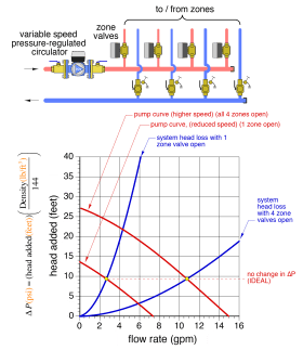
Figure 7-4c shows how a variable-speed circulator configured for constant differential pressure would maintain approximately constant differential pressure across the headers supplying the zones. This allows the flow rate in each zone to remain stable regardless of what zones are operating.
When a zone valve closes, the circulator running at its current speed attempts to increase the pressure difference between its inlet and outlet. However, a variable-speed pressure-regulated circulator quickly senses this tendency and responds by decreasing its speed. As speed decreases, the circulator’s pump curve shifts down and left, as shown in Figure 7-4c. Within a few seconds, the circulator will settle to a speed where the user-set differential pressure exists. The net effect is that active zones remain at the same flow rate as they were before one of the zones closed. This process also works in reverse as another zone valve opens.
Error 5: Flow-restricting thermostatic mixing valves
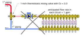
Discussion: It’s may seem intuitive to select a 3-way thermostatic mixing valve based on its pipe size. For example, if a piping circuit is built using 1-inch copper tubing, it would seem that a mixing valve with 1-inch piping connections is the proper selection, as shown in Figure 7-5a. Unfortunately, this often leads to significant flow restriction through the valve.
The underlying reason is that some 3-way thermostatic mixing valves are not specifically designed for use in hydronic systems. They are designed for use as antiscald devices in domestic hot water systems. In the latter application, a pressure drop of a few psi as water flows through the valve is generally not a problem. However, in a small hydronic system, a pressure drop of a few psi may represent most of the pressure differential that a small circulator can create.
Mixing valves should be selected based on their Cv values (a.k.a. flow coefficient) rather than the size of their piping connections. A Cv of 3.0 indicates that a flow rate of 3 gallons per minute of 60ºF water through the valve will result in a pressure drop of 1 psi across the valve. This pressure drop increases based on the following formula:
$$\Delta P= \bigg( {D\over 62.4} \bigg) \bigg({f\over Cv} \bigg)^2$$
Where:
$\Delta P= pressure drop across valve$
$D$ = density of fluid $(lb/ft^3)$
$f$ = flow rate through valve $(gpm)$
Thus, a valve with a Cv of 3.0 would have a pressure drop of 1 psi at a flow rate of 3 gpm, a pressure drop of 4 psi at 6 gpm, and a pressure drop of 16 psi at 12 gpm. Notice that pressure drop increases rapidly with increasing flow rate.
If a mixing valve with a Cv of 3.0 was placed in a circuit that was expected to operate at 10 gpm, and the large pressure drop of the valve at this flow rate was overlooked when the circulator was selected, the flow rate in the circuit would be far less than expected, and so would the rate of heat transfer by the circuit. Unfortunately, this is a common error in many North American hydronic systems.
Solution: Use a mixing valve with a Cv value that is approximately equal to the intended flow rate through the valve. Thus, if a circuit is supposed to operate with a 10 gpm flow rate, it would be appropriate to select the valve with a Cv of approximately 10.
3-way motorized mixing valves that are designed to be operated by an electrical actuator typically have higher Cv values than valves designed for domestic water-mixing applications.
idronics™ #7 provides a description of how to size and select several types of mixing valves.
Common Errors in Primary/Secondary Distribution Systems
The relationship between the primary and secondary circuits in a primary/secondary system is important. Unfortunately, this relationship is sometimes compromised by trying to combine other piping techniques in an attempt to circumvent issues such as the sequential temperature drop from one set of closely spaced tees to another in a series primary loop.
Error 6: An undefined piping assembly
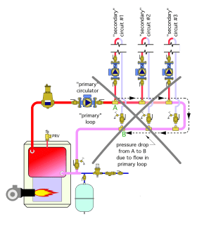
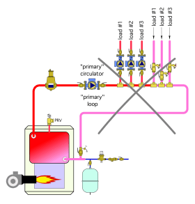
Discussion: One common error associated with attempts at creating primary/secondary piping is shown in Figure 7-6a.
This piping arrangement is the likely result of someone beginning to design a system based on use of a primary loop, but in the process, reverting to the concept of “headers” when connecting the load circuits to that primary loop. The result is neither a primary/secondary system, nor any other acceptable piping topology.
The problem with this piping arrangement is the pressure differential created by head loss along the primary loop. This pressure differential can induce flow through one or more of the load circuits when those circuits are not supposed to be delivering heat.
For example: Consider the pressure drop from point A to point B along the primary loop shown in Figure 7-6a. This pressure drop is due to head loss created by flow moving along the primary loop. Once this pressure drop exceeds the forward opening threshold of the spring-loaded check valves in a given circulator, flow will be pushed through that circulator and its associated circuit. This will deliver heat to the space served by that circuit when there is no call for such heat.
Solution: Either design a proper primary/secondary system using closely spaced tees, or design a different (but established) piping arrangement. Do not “morph” the two concepts together, as represented in Figure 7-6a.
Error 7: Incorrect placement of “closely spaced” tees
Discussion: Another “intuitive” but flawed attempt at eliminating the sequential temperature drop in a series primary loop is shown in Figure 7-7a.
In this system, the upstream tees for each of the three “secondary circuits” have been placed upstream of the three return tees. The rationale is that this allows each secondary circuit to operate at the same supply water temperature. The tees remain “relatively” close, so the head loss between them is “relatively” small.
This scenario will only function as intended when the flow rate in the primary loop is greater than or equal to the sum of the flow rates in all active secondary circuits. If this condition is not met, there will be a flow reversal in the pipe between the upstream group of three tees and the downstream group of tees. This flow reversal will create a mixed water temperature condition at the upstream tees.
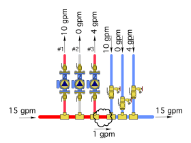
Assume the first zone circulator was operating at a flow rate of 10 gpm, the second zone circulator was off and the third zone circulator was operating at a flow rate of 4 gpm. Also assume that the flow rate created by the primary circulator was 15 gpm. This would produce the result shown in Figure 7-7b. All zones would be receiving water at the same temperature. So far, so good.
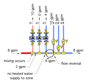
Now assume all zone flow rates remain the same, but reduce the flow rate in the primary loop from 15 to 8 gpm. The result is shown in Figure 7-7c.
In this scenario, the flow between the 3rd and 4th tee has reversed. This is the only possibility, since the flow entering any portion of the system has to be the same as the flow leaving that portion of the system.
There is no heated water entering zone #3, and the flow sent into zone #1 will be mixed (8 parts heated water with 2 parts return water). This will obviously have detrimental effects on heat delivery to these zones.
There are many other possibilities for what might happen based on assumed primary loop flow rate and the combined zone flow rates. However, this piping arrangement will only produce the expected equal supply temperature to each zone circuit if the flow rate in the primary loop is always greater than or equal to the sum of the zone flow rates.
Solution: One could argue that use of a large circulator could ensure that the primary loop flow rate is always greater than the sum of the secondary circuit flow rates. However, a larger circulator would have a high installation and operating cost. The best solution is to avoid this piping configuration and stick with proven piping arrangements.
Error 8: Incorrect placement of secondary circulator
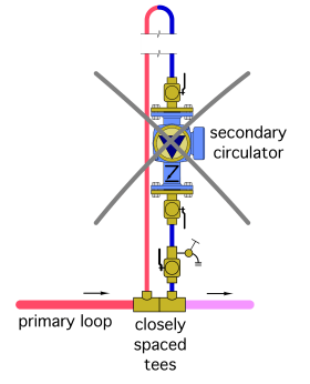
Discussion: The expansion tank in most primary/ secondary systems is connected to the primary loop. This makes the primary loop the pressure “reference point” for the secondary circuit. From the perspective of the secondary circulator, one can think of the connection between the primary loop and secondary loop as if it were a point of no pressure change. If the secondary circulator is installed on the return side of the secondary loop, as shown in Figure 7-8a, its pressure differential will produce a drop in pressure within the secondary circuit. This is not desirable. If the pressure at any point in the secondary circuit drops below the vapor pressure of the fluid being circulated, that fluid will boil. If the pressure drops below atmospheric pressure at a location where a float-type air vent or a valve with a loose packing nut is located, air will be drawn into the circuit.
Solution: For these reasons, it is best to locate the secondary circulator on the supply side of a secondary circuit, as shown in Figure 7-8b.
This placement allows the pressure differential created by the secondary circulator to increase the pressure within the secondary circuit. In effect, the secondary circulator is now “pushing” fluid though the secondary circuit, rather than “sucking” fluid through that circuit.
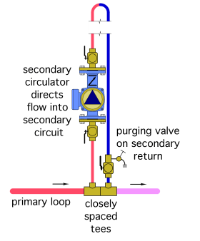
Error 9: Lack of protection against thermosiphoning
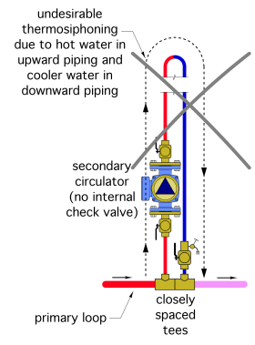
Discussion: Hot water is less dense, and therefore “lighter” than cool water. Whenever a hydronic circuit contains a source of hot water, vertical piping, and no means for blocking flow, thermosiphoning will develop. Hot water will rise from the heat source, cool as it passes through the piping and heat emitters, and “sink” downward through the return side of the circuit. This is illustrated in Figure 7-9a.
Secondary circuits located above a primary loop, and lacking a means of thermosiphon prevention, will experience thermosiphon flow. This can deliver heat into areas of the building where it is neither needed or desired. For example, consider a situation where a primary loop is delivering hot water to an indirect water heater during a hot summer day. Any unprotected secondary circuit with upward routed piping will allow some heat to migrate to the heat emitters in that circuit, perhaps on a day when that building’s air conditioning is operating. Such a situation must be avoided.
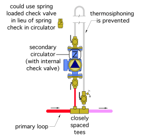
Figure 7-9b shows proper piping using either of the spring-loaded check valve options.
All of these devices require a slight forward opening pressure of 0.3 to 0.5 psi, which is generally sufficient to block the weak pressure differentials created by buoyancy differences between heated supply water and cooler return water in hydronic systems with no more than 25 feet of vertical rise. This vertical rise is based on the possibility of water at 180ºF in the primary loop, water at 70ºF on the return side of the secondary circuit, and a forward opening resistance of 0.3 psi in the springloaded check valve.
Error 10: Excessive pressure drop between tees.
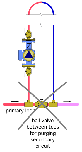
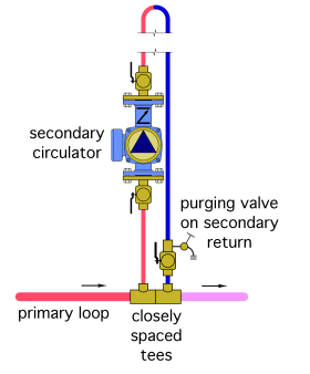
Discussion: The rationale for using closely spaced tees is to minimize the pressure drop between them. Anything that adds flow resistance between the tees will reduce their ability to provide hydraulic separation.
One common practice that can be a problem is placing a ball valve between the two tees, as shown in Figure 7-10a.
The valve is only used for routing purging flow from the primary loop through the secondary circuit during system commissioning, or following servicing.
Although the pressure drop through a “full-port” ball valve is small compared to other types of valves, it may still represent the equivalent of 1-2 feet of tubing. A “standard-port” ball valve will create even higher pressure drop.
Solution: A preferred detail is to install a purging valve at the end of each secondary circuit, as shown in Figure 7-10b.
Error 11: Use of two underslung thermal traps
Discussion: Even in systems where forward thermosiphon flow is prevented using a spring-loaded check valve or flow check valve, it is possible for a slight thermosiphon flow to develop in the return side of a secondary circuit that is located above the primary loop. This is the result of weak 2-directional flow within the return pipe. Hot water passes upward through the “core” of the pipe, while cooler water against the pipe wall flows downward. Although this is a weak flow compared to forward thermosiphoning, it can be prevented.
One of the “classic” approaches to stopping thermosiphoning in the return pipe of a secondary circuit is by installing a thermal trap that is at least 12 inches deep.
One might assume that if a thermal trap is effective at preventing thermosiphoning on the return side of a secondary circuit, it should be equally effective on the supply side of the circuit, and thus eliminate the need for a spring-loaded check valve or flow check on that side of the circuit. This is not true, as illustrated in Figure 7-11a. The underlying cause is that each thermal trap is buoyancy neutral. Neither trap induces a tendency for flow to develop in the secondary circuit. However, once that circuit is operating, the supply side of the circuit above the primary loop is filled with heated water, while the return side is filled with cooler water. The buoyancy differences between these columns of water will sustain a forward thermosiphon flow after the secondary circuit turns off. This flow will continue until the primary loop cools off, which denies the supply side of the circuit more hot water.
Solution: Do not use a thermal trap on the supply side of the secondary circuit. Use a spring-loaded check valve or weighted-plug flow check, as previously discussed.
Common Errors in Multi-Circulators Systems
Error 12: Lack of hydraulic separation
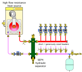
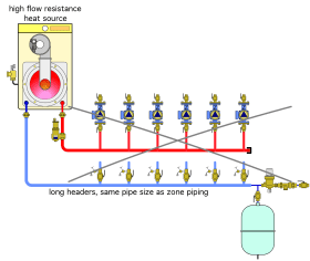
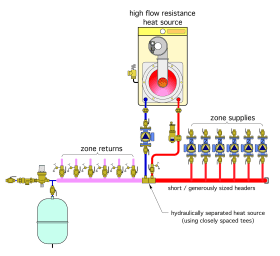
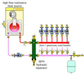
Discussion: One common error in many multi-circulator systems is a lack of detailing to provide hydraulic separation between the circulators. This may be the result of routing the combined system flow through a high flow resistance heat source. It can also result from undersized or excessively long header piping. Although both errors can occur individually, Figure 7-12a combines them into the same system.
Solution: The high flow resistance heat source should be hydraulically separated from the distribution circulators and equipped with its own circulator. The distribution headers should be sized for a flow velocity of 2 to 4 feet per second, and kept as short as possible. Both of these details are shown in Figure 7-12b.
Another solution is to install a hydraulic separator between the high flow resistance heat source and the distribution headers, as shown in Figure 7-12c. The Caleffi SEP4 hydraulic separator also eliminates the air separator shown in Figure 7-12c, and provides magnetic particle and dirt separation for the system.
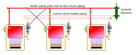
Error 13: Unnecessary use of reverse return piping
Another detail that, while not necessarily “wrong,” remains nonessential, is shown in Figure 7-13a.
Discussion: The use of reverse return header piping as a means to provide equal flow through identical devices (in this case boilers), each with their own circulator, is unnecessary.
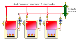
Solution: A simpler approach to providing approximately equal flows is to keep the header as short as possible, and generously sized, as shown in Figure 7-13b.
The header piping in combination with the hydraulic separator is providing the hydraulic separation between the three boiler circulators. As such, it should have a low head loss. A suggested criterion is to size the headers for a flow velocity of 2 to 4 feet per second when all circulators are operating.
In most cases, it is not essential to have exactly the same flow rate through identical heat sources. A slight variation in flow will only yield a slight variation in temperature rise. These variations are typically eliminated when the flows from simultaneously operating identical heat sources are combined at a hydraulic separator or other device.
If the flow rate must be identical, the same piping as shown in Figure 7-13b can be used with an individual flow measuring/balancing valve added to each heat source circuit. All circulators can be turned on, and each flow-balancing valve adjusted until the desired flow through each heat source is attained.
Common Errors in Mixing Applications
There are several errors that commonly occur when integrating mixing into hydronic distribution systems.
Error 14: Lack of boiler protection detailing
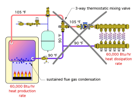
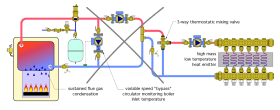
Discussion: A common error found in many systems that combine a conventional boiler with a lower temperature distribution system is not protecting a conventional boiler against sustained flue gas condensation when it is coupled to a low temperature distribution system. The schematic in Figure 7-14a shows a typical (but incorrect) arrangement.
The 90ºF water returning from the low temperature heat emitters divides up between the cool port of the 3-way thermostatic mixing valve and the pipe leading back to the boiler. There is no detail that senses or reacts to boiler inlet temperature. Furthermore, the return water temperature may never increase to a nominal 130ºF, even after hours of sustained operation. That’s because the low temperature distribution system has achieved thermal equilibrium with the boiler. The rate of heat production at the boiler equals the rate of heat dissipation from the distribution system. This occurs when the water temperature supplied to the heat emitters reaches 105ºF. There is no need for the supply water temperature to climb and higher, and thus the return water temperature will also remain at (or in some cases less than) 90ºF.
This arrangement is sure to allow sustained flue gas condensation, leading to corrosion of the boiler and vent connector piping, and damage to masonry chimneys. This system also violates the previously discussed prerequisite of having two mixing points when a conventional boiler is paired with a low temperature distribution system. The only mixing point in this system is the one within the 3-way thermostatic mixing valve, which controls supply water temperature.
Solution: Always provide a means of boosting boiler inlet temperature when a conventional boiler is used to supply a lower temperature distribution system. The solution must include hardware that senses and reacts to boiler inlet temperature, as well as two mixing points, one for supply temperature control and the other to boost boiler inlet temperature. It must also allow the boiler to be completely uncoupled from the distribution system when necessary to raise boiler inlet temperature as quickly as possible.
idronics™ #7 describes several options for providing boiler protection.
Error 15: Expecting a “bypass circulator” to provide boiler protection
Discussion: To properly protect a conventional boiler from operating with sustained flue gas condensation under all conditions, there must be a way to completely “uncouple” heat transfer from the heat source to the load. This is especially critical when the load has high thermal mass and operates at low water temperatures.
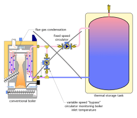
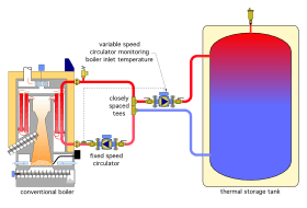
The system shown in Figure 7-15a uses a variable-speed “bypass circulator” to monitor the inlet temperature to a pellet-fueled boiler. The load is a large thermal storage tank that, at times, may be near room temperature.
The variable-speed circulator is set to speed up when the boiler inlet temperature is below some minimum boiler inlet temperature, such as 130ºF. The intent is to drive a significant flow of supposedly hot boiler water into the tee below the variable-speed circulator. This hot water would then mix with cooler water returning from the lower portion of the thermal storage tank, to keep the boiler inlet water temperature high enough to prevent sustained flue gas condensation.
Although well intended, this method of boiler protection is flawed.
Consider a situation where the water coming back from the lower portion of the thermal storage tank is 90ºF. This is well below the dewpoint temperature of the flue gases in the boiler, so the variable-speed circulator is likely to be running at or close to full speed. The circulator carrying flow to the tank is also running. The combined flow rate of these two circulators will be passing through the boiler. Under such a condition, the temperature rise across the boiler, even at maximum boiler output, is likely to be far less than 20ºF. Thus, the anticipated “hot” water needed to bring the blended flow entering the boiler above 130ºF is simply not present. No amount of “bypass flow” can remedy this situation. Under such conditions, the boiler will operate with sustained flue gas condensation. Furthermore, this situation could last for hours, based on the volume and initial water temperature of the thermal storage tank. Fundamentally, this detail fails to provide a means to totally prevent heat flow from the boiler to the load.
Figure 7-15b shows another scenario in which a high thermal mass heated floor slab is supplied through a 3-way thermostatic mixing valve, and boiler protection is intended to be provided by the variable-speed bypass circulator.
Although there is mixing to control the supply water temperature, the inability of this arrangement to totally stop heat flow between the boiler and load when necessary removes its ability to properly protect the boiler from sustained flue gas condensation.
Solution: Figure 7-15c shows how the system of Figure 7-15a could be modified to provide proper boiler protection.
The variable-speed setpoint circulator is now located where it can completely stop any heat transfer between the boiler and thermal storage tank. The closely spaced tees provide hydraulic separation between the fixed-speed boiler circulator and the variable-speed boiler protection circulator. The variable-speed circulator remains off until the boiler inlet temperature climbs to some minimum value (typically 130ºF) that can prevent sustained flue gas condensation. The variable-speed circulator then increases speed, but continues to monitor boiler inlet temperature. If that temperature decreases, the variable-speed circulator decreases speed to reduce the rate of heat transfer from the boiler to the thermal storage tank. If the boiler inlet temperature continues to rise, so does the speed of the variable-speed circulator. The variable-speed circulator typically reaches full speed when the boiler inlet temperature is above the minimum boiler inlet temperature setting by 5 to 10ºF.
Error 16: Incorrect placement of circulator relative to mixing valve
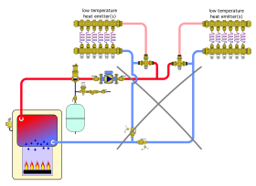
Discussion: There must be a circulator between a mixing valve and the heat emitters served by that mixing valve. The schematic shown in Figure 7-16a fails to provide the required circulators.
Water discharged from the circulator shown in Figure 7-16a will favor the path of least resistance when returning to the circulator’s inlet. This will not allow proper mixing within the 3-way thermostatic valves, and therefore will not deliver heat at the required rate or supply water temperature to the low temperature heat emitters. The schematic in Figure 7-16a also fails to provide boiler protection, and thus allows sustained flue gas condensation within the boiler.
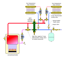
Solution: The system shown in Figure 7-16b places a circulator downstream of each mixing valve. It also includes a high flow capacity 3-way thermostatic valve for boiler protection.
Error 17: Lack of hydraulic separation, and possible flow reversal
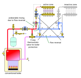
Discussion: The system shown in Figure 7-17a embodies two significant errors.
The first error is a lack of hydraulic separation between the boiler loop circulator and the two zone circulators. When the boiler has reached a stable operating temperature above the dewpoint of the flue gases, the hot port of the boiler protection mixing valve will be closed. Under this condition, the boiler loop circulator will create a significant pressure differential between the supply and return headers to which the zone circuits are connected. This pressure differential is imposed across both zone circuits and will push flow into both circuits. If one of the zones is off, the spool within the 3-way motorized mixing valve will remain in the last position it had when operating. This could allow a flow path through the 3-way mixing valve from the hot inlet port to the mixed outlet port. The imposed pressure differential will allow hot (unmixed) water to flow into the inactive zone, leading to possible space overheating, as well as a possible over temperature condition in the low temperature heat emitters (i.e., imagine 170ºF water being pushed into a radiant floor zone).
The other problem with the system in Figure 7-17a is lack of check valves that can prevent any reverse flow from an active zone through an inactive zone. A 3-way rotary valve that is not operating may present a flow path from the cool inlet port to the hot inlet port, and thus allow flow reversal through the valve. To stop this, a check valve must be located between the header connections and the mixing valve. A spring-check valve within the circulator will not be able to stop possible flow from the cool port to the hot port of the mixing valve. Some 3-way thermostatic valves contain internal check valve cartridges that could prevent such flow reversal, but 3-way rotary mixing valves do not contain any check valve cartridges.
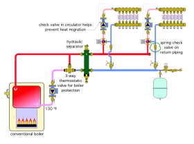
Solution: One solution that solves both problems is shown in Figure 7-17b.
This system uses a hydraulic separator to isolate the pressure dynamics of the boiler loop circulator from that of either zone circulator. The Caleffi SEP4 hydraulic separator also provides central air and dirt separation, as well as the ability to capture ferrous metal particles within the system.
A spring-check valve has been installed on the return side of each zone circuit between the mixing valve and return header. This check valve prevents flow reversal through either zone when it is inactive and the other zone is active.
When spring-check valves are located on the return side of the zone circuits, as shown in Figure 7-17b, it is still good practice to use zone circulators with internal spring-checks. These internal valves provide a forward opening pressure requirement of 0.3 to 0.5 psi, which is generally sufficient to prevent heat migration into the supply side of the zone circuit.


