PREFACE
Several methods for cooling commercial and institutional buildings have been developed based on the use of chilled water as the primary energy transport media. These methods offer several distinct advantages that cannot be matched by “all-air” systems. They include:
• Minimally invasive installation
• Reduced electrical energy usage
• Adaptability to many sources of chilled water
• Easy zoning
• No coil frosting
• Adaptability to radiant panel cooling
• Adaptability to chilled-beam cooling
• Possibility of use of rejected heat
• Adaptability to thermal storage
• Low refrigerant volume relative to VRF systems
Each of these advantages is briefly described in this section. They will be more fully explained and applied in later sections.
MINIMALLY INVASIVE INSTALLATION
The heat capacity of water is 62.4 Btu/ft3/ºF. The heat capacity of air is 0.018 Btu/ft3/ºF. The difference in this thermal property allows liquid water to absorb almost 3,500 times more heat than the same volume of air. This has profound implications regarding the size of the piping required to convey chilled water through a building versus the size of ducting required to move a thermally equivalent amount of air through that building.
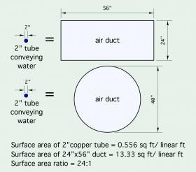
For example, a 2-inch copper tube carrying chilled water at a flow rate of 40 gallons per minute to a large air handler, and undergoing a temperature increase of 15ºF across the coil of that air handler, is absorbing heat at a rate of 300,000 Btu/hr. To do this with a duct operating at a face velocity of 1,000 feet per minute and an air temperature change of 30ºF would require a duct 24 inches deep and 56 inches wide, or a round duct about 40 inches in diameter, as shown in Figure 2-1. Accommodating such large ducts in commercial and institutional buildings usually requires a mechanical chase located above a suspended ceiling. This adds to building height as well as cost.
Piping carrying chilled water and ducting carrying chilled air require insulation to prevent surface condensation. The 24-inch x 56-inch rectangular duct shown in Figure 2-1 has 24 times more surface area compared to the 2-inch copper tube. Insulating the duct against surface condensation would require 24 times as much insulation material as using the same insulation on the copper tube. Undesirable heat gain into the duct will be substantially greater than that into the tube, assuming approximately equal internal temperatures and insulation R-values.
REDUCED ELECTRICAL ENERGY USAGE
A cooling distribution system operating with chilled water can use significantly less electrical power compared to a forced-air distribution system of equivalent thermal capacity. The difference can be expressed through a calculation of distribution efficiency, which is defined by Formula 2-1:
Formula 2-1
$$\mathrm{{Distribution\ efficiency=} {rate\ of\ heating\ or\ cooling\ delivery(Btu/hr) \over electrical\ power\ input\ to\ operate\ delivery\ system(watt)}}$$
Here’s one comparison: Published data for the blower in a geothermal water-to-air heat pump using forced-air delivery indicates that a 3/4-horsepower electronically commuted motor is required to deliver approximately 1500 CFM airflow through a duct system. The estimated electrical input power to this motor when operating at full capacity is 690 watts. The rated total cooling capacity of this heat pump is about
53,000 Btu/hr (based on 60ºF entering fluid temperature from the geothermal source). The heat pump’s distribution efficiency under these conditions is:
Formula 2-1a
$${\mathrm{Distribution\ efficiency=} {53,000\ Btu/hr \over 690\ watt}{=} {76.8}{Btu/hr \over watt}}$$
An equivalent hydronic system is assumed to have 200 feet equivalent length of 1-inch copper tubing. It will operate with a 10ºF chilled-water temperature rise across a radiant ceiling panel. The hydronic system uses a circulator with an electronically commutated motor with a wire-to-water efficiency of 40% The water flow rate required for delivering 53,000 Btu/hr at a 10ºF temperature change is:
Formula 2-1b
$${{f=} {\text{53,000} \over 500 \times \Delta T}{=} {\text{53,000} \over 500 \times 10} {=} \text{10.6gpm}}$$
Assuming a 200-foot total equivalent length for the circuit, the pressure drop in the circuit is 5.6 psi. The power supplied to the circulator can be estimated using:
Formula 2-2
$${\text{w }{=} {0.4344 \times f \times \Delta P \over e}{=} {0.4344 \times 10.6 \times 5.6 \over 0.40} {=} \ 64.5watt}$$
Where:
${\text w}$ = electrical input power to circulator (watts)
$f$ = flow rate through circulator (gpm)
$ΔP$ = pressure increase across circulator (psi)
$e$ = wire-to-water efficiency of circulator (decimal %)
Assume that 30% of the 53,000 Btu/hr total cooling load is latent cooling. This is handled by a small air handler with a blower operating at 150 watts.
The distribution efficiency of this hydronic delivery systemwould be the rate of heat transfer divided by the wattage of the circulator plus the wattage of the air handler blower. It can also be calculated using Formula 2-1:
$${\text{Distribution efficiency =} {\text{53,000}\ Btu/hr \over {(64.5w+150w)}}{=} { 247}{Btu/hr \over watt}}$$
This comparison shows that the chilled-water delivery system is using only about 36% of the electrical power required by the equivalent forced-air system. The circulator wattage (64.5 watts) was only about 9.4% of the power required by the blower in the heat pump. The 150-watt blower in the small air handler adds substantially to the total power required for the hydronic cooling method.
Hydronic cooling systems using radiant panels or chilled beams will have minimal ratios of total cooling capacity divided by fan or blower input power. Commercial and institutional buildings using these systems can
substantially reduce the electrical energy required to convey cooling throughout a building. Radiant panel cooling and chilled beams are discussed in more detail in Section 7.
It’s important to remember that all electrical input to a cooling distribution system ultimately becomes a heat gain to the building. When high energy efficiency is a primary design goal, it is imperative to minimize the
electrical input power required to create cooling effect AND move that effect through the building to where it’s needed. Properly designed hydronic distribution systems require significantly less electrical energy compared to thermally equivalent “all-air” systems.
CHILLED WATER OPTIONS
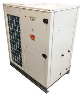
A wide variety of devices are now available to produce chilled water. They include the large dedicated (non-reversible) chillers often used in large high-rise buildings, as well as reversible heat pumps, and heat recovery chillers, such as shown in Figure 2-2. In some limited circumstances, it is also possible to use water from a lake to directly cool a building. These options are described in Section 5 (Traditional chilled-water terminal units).
EASE OF ZONING
Chilled-water cooling systems are very easy to zone. They can be designed around electrically operated zone valves in combination with variable-speed pressure-regulated circulators. This approach substantially reduces electrical energy consumption relative to systems using multiple zone circulators. Zoning also allows unoccupied areas to be minimally cooled, and thus reduces the energy used
by the chiller.
NO COIL FROSTING
Many air handlers and fan coils used for cooling have direct expansion (“DX”) coils. Liquid refrigerant flows into these coils and evaporates as it absorbs heat from the air stream passing across the coil. In some cases, the temperature of the refrigerant within the coil can be lower than 32ºF. This creates a potential for frost to form on the exterior surfaces of the coil — depending on the temperature and humidity of the air entering the coil. This undesirable effect is exasperated if the actual airflow rate across the coil is lower than the specified airflow, which could result from improperly designed ducting systems. Coil frosting will not occur with chilled-water coils, which operate well above 32ºF.
RADIANT PANEL COOLING
Chilled water can be used for radiant panel cooling. Ceiling surfaces are ideal for absorbing heat from the occupied space below. An example of a radiant ceiling that can provide both heating and radiant cooling is described in Section 7 (Radiant panel & chilled beam systems).
CHILLED-BEAM COOLING
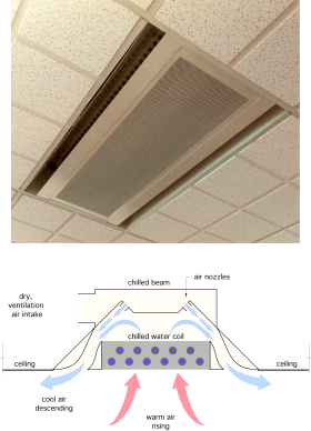
Chilled beams are specially designed heat absorption units that use chilled water to generate a gentle cooling airflow within a room using natural convection. They also serve as a terminal to gently supply ventilation air to occupied spaces, as shown in Figure 2-3.
Although relatively new to North America, chilled beams have been used in European buildings since the 1970s. Like radiant ceilings, they are only intended to handle a portion of the sensible cooling load. The distribution energy saved through use of chilled beams has proven to be as much as 50% lower than that required by VAV (Variable Air Volume) systems. Chilled-beam cooling is also known to be very quiet and comfortable. It is discussed in more detail in Section 7.
POSSIBLE USE OF REJECTED HEAT
The heat rejected from a water-cooled chiller may be of use for simultaneous space heating or process heating loads. One example is preheating (or fully heating) domestic water using the heat rejected from a water-to-water heat pump supplying chilled water for space cooling. Another is using the heat rejected from a water-cooled chiller to warm a swimming pool. In commercial buildings, it is common to have situations in which the core areas of the building require cooling, while the exposed perimeter areas of the building require heating. This is an ideal application for a water loop heat pump system, which is described in Section 8.
THERMAL STORAGE
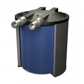
Chilled-water cooling is adaptable to thermal storage where preferential time-of-use electrical rates or lower nighttime ambient temperatures make this approach feasible. Ice-based thermal storage cooling systems use large water-filled tanks, such as shown in Figure 2-4.
Integrating ice-based thermal storage into hydronic-based cooling can also significantly reduce electrical power demand charges, as well as the size of the chiller(s) used. These systems are described in Section 9.
LOWER REFRIGERANT VOLUME
Chilled-water cooling systems contain far less refrigerant than equivalent variable refrigerant flow (VRF) systems. This is important for several reasons.
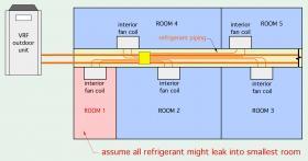
First, a leak in a commercial (VRF) system could lead to the loss of hundreds of pounds of refrigerant, in some cases inside the building. This is a dangerous possibility that could require emergency evacuation of the building. It’s also an expensive failure, and undesirable from the standpoint of releasing gases that contribute to climate change. ASHRAE standards 15 and 34 define specific refrigeration concentration limits. Those designing VRF systems should verify that the amount of refrigerant that could be released due to an interior leak, and the smallest interior space where such a leak could occur, are in conformance with these standards.
Second, the type of refrigerants used in current generation VRF systems may not be the same as those used in the future. There is currently a wide variety of research underway to develop new refrigerants with lower global warming potential. It’s also likely that when such refrigerants are available, environmental regulations aimed at replacing legacy refrigerants will be enacted. There is no guarantee that a currently installed VRF system will be compatible with future refrigerants or oils. Incompatibility could require a major equipment changeout. In contrast, any future hydronic chiller will remain compatible with a water-based distribution system.
Third, most VRF systems use proprietary controls that must be commissioned and serviced by specially trained technicians. This limits the building owner’s choices on maintenance as well as parts availability and cost.
Fourth, hydronic-based systems are adaptable to low power terminal units such as radiant panels and chilled beams, whereas almost all VRF systems use fan-equipped terminal units.
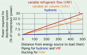
Finally, the electrical energy used to transport heating and cooling energy through a building, expressed as a percent of the chiller compressor power, is substantially lower in a properly designed hydronic system compared to either a VRF system, or a variable air volume (VAV) system of equivalent capacity, as shown in Figure 2-6.

