WINDOW AIR CONDITIONERS
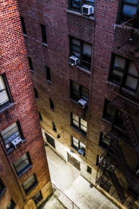
The low-end approach to cooling large buildings, especially older buildings used for apartments or condominiums, is to use window air conditioners that are temporarily installed in late spring and removed in fall. Window air conditioners are only useful in rooms with exterior walls and suitably sized windows. Although such rooms are common in residential buildings, this requirement significantly impedes their use in many non-residential commercial buildings, (i.e., those having rooms without exterior walls). Window air conditioners are also aesthetically unappealing. The sound that they generate is present in the space being conditioned. Their cooling efficiency is also lower than that of many other central cooling options. They are very limited in terms of how the forced-air stream is directed into the occupied space, and thus may create objectionable drafts. They require much more effort to install and remove each year compared to other, permanently installed options. In most cases, their use in commercial buildings is based on low installation cost, or the inability to accommodate any other cooling hardware.
PACKAGED TERMINAL AIR CONDITIONERS (PTAC UNITS)
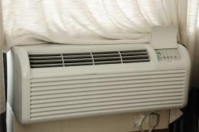
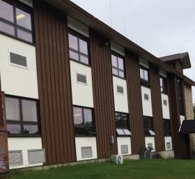
PTAC units are self-contained, and most are all-electric. They use a reversible heat pump refrigeration system to provide heating and cooling. They are installed through openings in exterior walls, and thus are not applicable in spaces without such walls. They supply heating or cooling to a room using forced-air circulation. They allow for individual temperature control in each room, and thus are popular in hotels.
Still, most people who have spent time in hotel rooms conditioned by PTAC units can attest that the comfort they provide is not ideal. A single point of high velocity air delivery into a room tends to create objectionable drafts. Undesirable fan noise is also present.
DUCTLESS MINI-SPLIT HEAT PUMPS
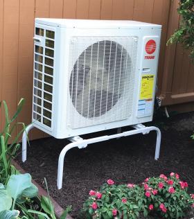
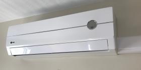
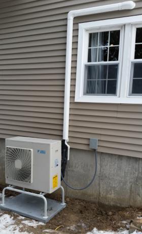
Another commercial cooling option is a multiple-head ductless mini-split air conditioner (or heat pump). In these systems, a single outdoor condenser can supply chilled refrigerant to several indoor wall or ceiling “cassettes,” which in turn supply cooled and dehumidified fan-forced air to occupied spaces. A typical outdoor condenser for small system is shown in Figure 3-3a. One of its associated wall cassettes is shown in Figure 3-3b.
Ductless systems require two refrigerant tubes between each indoor cassette and the outdoor condenser. They also require individual condensate drain tubes from each cassette to a suitable drain and wiring between each cassette and the condenser. Like PTAC units, ductless mini-split systems allow individual temperature control within each space where a cassette is mounted.
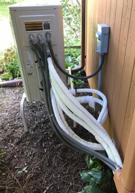
Ductless mini-split systems tend to be more expensive on a dollar per unit of cooling capacity basis compared to larger centralized systems. They are popular in retrofit applications because they eliminate the need for ducting. However, routing the refrigeration tubing, wiring and condensate drain to each interior cassette, especially in retrofit situations, can be challenging. When interior routing is difficult or impossible, the tubes and wires are routed along the exterior of buildings, which compromises aesthetics, as seen in Figure 3-5.
VARIABLE REFRIGERANT FLOW (VRF) SYSTEMS
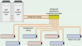
In larger commercial buildings the concept of ductless mini-split systems can be expanded into a variable refrigerant flow (VRF) system. One or more outdoor condenser units can supply refrigerant to many (in some cases over 100) indoor cassettes. Figure 3-6 shows the basic topology of a VRF system.
Unlike ductless mini-split systems, most VRF systems allow some indoor cassettes to operate in cooling while others operate in heating. A common situation in commercial systems is when a room with an exterior exposure requires heating while an interior room requires cooling. VRF systems can handle these situations using refrigerant management controls. This makes them popular for hotels and other buildings where many independently controlled zones are required.
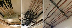
Large VRF systems can contain miles of copper refrigerant piping routed throughout the building, as seen in Figure 3-7. There can be hundreds of brazed or compression connections connecting this tubing. There can also be hundreds of pounds of refrigerant contained in the system, much of it within interior space. A leak or rupture in an interior refrigerant line could create a very dangerous situation requiring evacuation of the building.
ROOFTOP UNITS
Air conditioning, ventilation, and in some cases heating, can also be supplied from rooftop forced-air units. These systems are commonly used on low-rise commercial or institutional buildings with flat roofs.
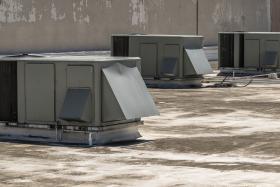
A typical rooftop unit mounts to a curb that has been secured and sealed to the flat roof of a building, as shown in Figure 3-8. Supply and return air ducts connect to the rooftop unit through the opening in the curb. Cooling is provided by a direct expansion refrigeration system. Outside air for ventilation enters the unit through a modulating damper. Heating can be supplied by the refrigeration system (operating as a heat pump), or by burners supplied by natural gas. The ducting system can be routed to several air diffusers within the building.
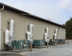
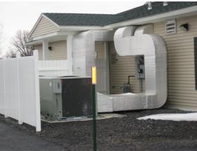
Because they are “all-air” systems, rooftop units are limited to applications where the supply and return ducting can be accommodated within the building. In most cases, this requires a mechanical plenum space above the suspended ceiling at each floor of the building. The height of the plenum space depends on the size of the ducting that must be routed through it. The ducting for all-air systems must be sized to accommodate the full (sensible + latent) cooling load, as well as the ventilation airflow requirement. Rooftop units are also directly exposed to the elements, which tends to shorten their service life relative to cooling systems with mostly indoor components. Rooftop units that provide heating experience higher heat losses compared to heating appliances that are housed inside buildings. Some rooftop units can also be configured for ground mounting. However, some ground-mounted “rooftop” units infringe on building appearance, as shown in Figures 3-9a and 3-9b. The long-term maintenance of insulated exterior ducting can also prove challenging. Although they are a convenient means of providing cooling in low rise commercial or institutional buildings, they do not offer the versatility of hydronic-based systems.
“CLASSIC” CHILLER/TOWER COOLING FOR LARGER BUILDINGS
Chilled water cooling has been used for several decades in commercial and institutional buildings such as high-rise hotels and offices buildings. One of its chief attractions, as previously discussed, is the ability to move “cooling effect” over large distances using pipes that are much smaller than ducting of equivalent thermal capacity.
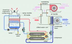
Figure 3-10 illustrates the make-up of a “classic” — and very basic — commercial chilled water-cooling system. It will be referred to as a “chiller/tower” system.
The chiller in this system is shown in the dashed lines. It contains the major components of any electrically powered refrigeration system: a compressor, evaporator, condenser and expansion device. The evaporator and condenser are both heat exchangers that separate the refrigerant from water but allow rapid heat transfer between these fluids.
Small chillers typically use hermetically sealed compressors (e.g., where the motor and mechanical portions of the compressor as enclosed in a sealed steel shell). Older chillers may have reciprocating compressors that use one or more pistons mounted to a crankshaft to compress the vaporous refrigerant. Modern hermetic compressors typically use orbiting scrolls to compress the refrigerant. Larger chillers often use screw compressors or centrifugal compressors driven by large 3-phase electric motors. In all cases, the compressed refrigerant exits the compressor at much higher pressures and temperatures in comparison to those entering the compressor.
The condenser releases heat to a stream of water that flows through a cooling tower. As this warm water flows through the cooling tower, it is cooled by the combined action of upward airflow and a downward spray of water.
The two most common types of electrically powered chillers are:
• air-cooled chillers
• water-cooled chillers
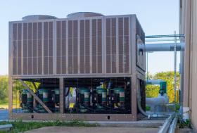
Air-cooled chillers are usually located outside buildings, often on rooftops. They contain a complete refrigeration system, which absorbs heat from a stream of water supplied to the chiller from the building’s hydronic cooling system. The temperature of this heat is increased by the refrigeration system and released to outside air through large refrigerant-to-air heat exchanger coils that serve as condensers for the refrigeration cycle. Large fans create a strong airflow past these coils. Cold water produced by the chiller returns to the building’s hydronic cooling system.
Figure 3-11 shows a large, multi-stage, air-cooled chiller mounted outside a cool storage warehouse. This unit includes several staged hermetic compressors, along with multiple condenser coils and multiple fans.
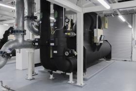
Water-cooled chillers are usually located inside buildings and are more commonly used in larger systems. They also consist of fundamental refrigeration components including an evaporator, condenser, compressor and expansion device. However, water-cooled chillers transfer heat gathered from the building into a stream of water rather than directly to outside air. That water stream is circulated through a heat dissipation device, such as a cooling tower or geothermal earth loop, where the heat is rejected.
Figure 3-12 shows an example of a large water-cooled chiller with a centrifugal compressor. This type of chiller is commonly used in large commercial and institutional chilled water-cooling systems.
In most applications, the typical leaving water temperature from modern chillers ranges from about 40 to 60ºF. However, some chillers can create significantly lower temperatures when operating with an antifreeze solution rather than water.
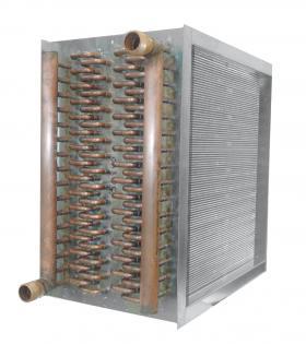
Cold water from chillers is routed through piping within the building to one or more terminal units. In Figure 3-10, the terminal unit is an air handler equipped with a chilled-water coil. That coil consists of an array of smaller diameter copper tubes mechanically bonded to closely spaced aluminum fins. Figure 3-13 shows an example of a “thick” chilled-water coil with several rows of tubes.
Return air from the building, as well as some outdoor air to meet ventilation requirements, is pulled across the coil by a blower in the air handler. As it passes through the coil, the air is cooled (e.g., its temperature is lowered), and in most cases, the moisture content of the air is reduced. The latter is called dehumidification, or “latent” cooling, which will be explained in more detail in the next section.
The “conditioned” air leaving the air handler is pushed through a ducting system to several air diffusers in the building. Larger buildings generally have multiple air handlers to reduce the space requirement and routing constraints associated with large ducts.
The air handler shown in Figure 3-10 also has an exhaust blower and modulating dampers. These components are used to regulate the amount of outside air admitted to the building and to provide a controlled means of exhausting stale air from the building.
The cooling tower shown in Figure 3-10 is more specifically classified as an “evaporative” cooling tower. It is further classified as a “closed” cooling tower.
The water stream from the condenser remains within piping inside the tower and doesn’t mix with the “sump” water being sprayed over the piping to create evaporative cooling. A large fan at the top of the tower pulls outside air through louvers at the base. Some cooling towers are designed as “open” units. The warm water stream from the chiller’s condenser is directly exposed to outside air within the tower. The water stream leaving the cooling tower flows back to the condenser to absorb additional heat as it is being created.
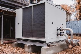
Water from the sump at the base of the tower is pumped through an array of nozzles near the top of the tower. Some of this water evaporates when it contacts the piping carrying warm water from the chiller’s condenser. This significantly increases the heat dissipation ability of the tower, especially on low-humidity days. Additional water is automatically added to the sump at the base of the tower to replace the water that has evaporated. The cooled (but not chilled) water then flows back to the chiller’s condenser to absorb additional heat. Figure 3-14 shows an example of a cooling tower that is part of a commercial chilled-water cooling system.
There are many variations of the “classic” chilled-water cooling system just described. Larger systems may have two or more chillers. Those chillers may have the ability to modulate refrigerant flow, and thus vary cooling capacity. Multiple variable-speed circulators and modulating valves may be used to manage chilled water flow through the chilled-water distribution system. Two or more cooling towers, each with variable water and airflow capability might be used to adjust heat dissipation capacity to the current cooling load.
WATER-SIDE ECONOMIZERS
Some large chilled-water cooling systems are designed around “water-side economizers.” These systems have a large plate & frame heat exchanger, commonly referred to as an “economizer,” between the cooling tower and chilled-water distribution system. On days when the outdoor air temperature is relatively low, it’s possible to supply the chilled-water distribution system directly from this heat exchanger without operating the chiller, or with the chiller operating at minimal cooling capacity. These modes of operation use much less electrical energy compared to a standard mode where all cooling is provided by the chiller. ASHRAE Standard 90.1 now requires evaluation of water-side economizers in otherwise “classic” chiller/tower cooling systems for installations in climate zone 4 or higher.
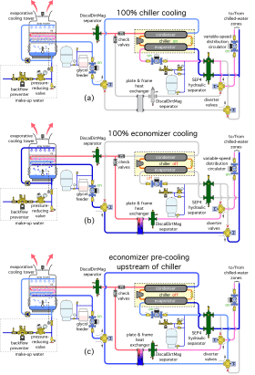
Figure 3-15 shows one piping configuration for a chiller/tower system that includes a water-side economizer.
The system in Figure 3-15 uses two 3-way diverter valves and one 3-way modulating valve. It also uses a SEP4 hydraulic separator to interface the evaporator side of the chiller to the system. This separator allows the chiller to maintain a minimum flow rate when the demand from a zoned distribution system is low. It also provides air, dirt and magnetic particle separation for the system.
In Figure 3-15a, the position of the valves and circulator operation are in the mode where the chiller provides 100 percent of the cooling load. This mode applies when outdoor conditions are warmer than the return water from the cooling distribution system. The water-side economizer is not functioning in this mode.
In Figure 3-15b, the position of the valves and circulator operation allows the plate & frame heat exchanger (e.g., the economizer) to assume 100 percent of the cooling load. This mode applies when the outdoor temperature is below the return temperature from the cooling distribution system — but is still several degrees above freezing. This is also the mode that yields the greatest reduction in operating cost since the chiller is completely off. The only significant electrical power being used is for the circulators.
In Figure 3-15c, the system is using the plate & frame heat exchanger to pre-cool the water returning from the cooling load, and then passing that water to the chiller to further lower its temperature to the desired setpoint. The pre-cooling removes some of the chiller load and lowers its power demand. A modulating 3-way valve controls the portion of flow from the cooling tower to the heat exchanger and the chiller. This mode of operation is appropriate when the outdoor temperature is low enough to allow some pre-cooling, but not enough to drop the chilled water temperature to the desired setpoint. As the outdoor temperature decreases, more of the tower flow is directed through the heat exchanger and less through the chiller, and vice versa.
Cold water from the building is supplied to the sump in the cooling tower through an automatic make-up assembly. A float switch inside the cooling tower monitors the water level in the sump. When the water level drops, the float switch operates a solenoid valve to allow water into the sump. This make-up water passes through a testable backflow preventer and a pressure-reducing valve upstream of the solenoid valve.
The closed cooling tower circuit operates with an antifreeze solution. If the tower will be inactive in winter, its sump water would be drained.
The heat exchanger in the cooling tower and the economizer heat exchanger are protected against dirt that could foul the heat transfer surfaces by DiscalDirtMag® separators. These separators also collect air entrained with the water and eject it from the system.
Water-side economizers are especially well-suited to chiller/tower systems serving with a high percentage of sensible cooling load. Examples include data centers or industrial cooling in arid climates. These loads allow for higher chilled water temperatures, and thus increase the hours where the economizer can provide most, if not all, of the cooling requirement. They are also well-suited for applications where a high percentage of the sensible cooling load is handled by radiant panel cooling or chilled beams, and the latent load is handled by a separate chiller operating at a lower water temperature.
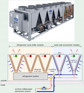
Some air-cooled chillers are now available with optional water side economizers. One modular approach places a section of water-to-air coils that form the economizer next to the refrigeration-based hardware, as illustrated in Figure 3-16.
The number of economizer modules, as well as the number of refrigeration-based modules, can be varied depending on the cooling capacity required, the ratio of sensible versus latent cooling, and the climate where the unit is installed. Applications with high sensible cooling ratios, or those using radiant cooling and/or chilled beams, allow for warmer chilled water temperatures, and thus extended the range of outdoor conditions over which the economizer can be used. Applications in hot/humid climates would likely require more refrigeration-based modules but still provide for limited use of the water-side economizer during winter. The modular approach also allows cooling capacity to be controlled in stages, and sometimes with variable-speed modulating within stages.
CHILLER EFFICIENCY
There are several indices that are used to express the cooling efficiency of chillers. The one that is used usually depends on the cooling capacity of the chiller and if it operates as an on/off device or a variable-capacity device.
For large water-to-water chillers, the efficiency index used to measure efficiency has been kilowatts of electrical input power per ton (12,000 Btu/hr) of cooling capacity. Modern centrifugal chillers operating at full load, and using HFC-134a refrigerant, can attain efficiencies in the range of 0.55 Kw/ton.
The efficiency of smaller chillers is often expressed as an Energy Efficiency Ratio. EER is the cooling output in Btu/hr divided by the electrical input power in watts, both of which are measured at industry standardized conditions for entering air and water.
Another efficiency index used for variable-capacity chillers is called Integrated Part Load Value (IPLV). This rating, which is based on AHRI standard 550/290, is meant to approximate the seasonal efficiency that a variable-capacity chiller could achieve when subject to a wide range of operating conditions over a representative cooling season. IPLV is based on Formula 3-1.
Formula 3-1:
$$IPLV= 0.01A+ 0.42B + 0.45C + 0.12D$$
Where:
$IPLV$ = Integrate Part Load Value
$A$ = EER of chiller operating at 100% capacity
$B$ = EER of chiller operating at 75% capacity
$C$ = EER of chiller operating at 50% capacity
$D$ = EER of chiller operating at 25% capacity
Formula 3-1 “weights” the EER of the chiller based on the assumption that it operates at full capacity for 1% of the cooling season, 75% capacity for 42% of the season, 50% of capacity for 45% of the season, and 25% capacity for 12% of the season. When chillers operate at reduced capacity, their instantaneous EER increases based on lower rates of heat transfer through the same amount of heat exchange area. The IPLV is meant to capture this improved performance under part load conditions in a standardized manner. It allows designers to compare the performance of different variable-capacity chillers.
CONTINUING IMPROVEMENT
Commercial chilled-water cooling systems have evolved significantly since first being used in the late 1920s. The two primary goals of this evolution have been to:
• Reduce the electricity used, or in the case of absorption chillers, the fossil fuel used, to create suitable chilled water.
• Improvements to hydronic delivery systems that reduce circulator power in chilled-water distribution systems.
• Other refinements including:
• Improved load matching between the devices producing chilled water and concurrent cooling loads.
• Use of naturally cool outside air or water when available to reduce (or eliminate) the need for refrigeration-based cooling.
• Use of alternative heat dissipation sub-systems, such as geothermal earth loops, that reduce reliance on cooling towers.
• Designing systems to reduce peak loading on electrical utilities.
Later sections provide overviews of several contemporary hydronic-based cooling systems for commercial and institutional buildings that leverage these refinements.
Optimal operation of any chilled-water cooling system requires good hydronic design and detailing. For example, it’s imperative to keep all heat transfer surfaces in the chiller clear of dirt and scale. It’s also important to properly balance water flow through each of several chilled-water terminal units in the system. Chilled-water systems also need to be free of air and have properly sized expansion tanks. These details can be accomplished with modern hydronic system components. Several will be discussed as you read on.

