PREFACE
There are many ways to provide space heating, cooling and domestic water heating in all-electric net-zero buildings. They range from separate systems for each load, to integrated approaches that leverage energy recovery and energy management to minimize consumption and coordinate the needs of building occupants with the real-time status of the utility grid.
This section describes the advantages and benefits of using hydronic-based systems in low-energy and net-zero buildings. It also discusses some of the hydronic heating and cooling hardware that’s appropriate for these applications. Later sections will show specific details and example systems.
SUPERIOR THERMAL COMFORT
Although some energy enthusiasts are willing to live in buildings that minimize energy use at the expense of widely varying comfort, this is not true for most North American consumers. History has shown that approaches to space heating and cooling that require sacrifices in comfort to achieve high energy-efficiency targets or absolute minimum energy use, usually fail to gain significant market share. The lesson learned: Comfort, has been and remains one of the most important underlying factors in establishing and maintaining a market for building energy systems.
Human thermal comfort is determined by the interaction of processes the body uses to dissipate metabolic heat production, as well as the environmental conditions within the occupied space. These include air temperature, air temperature stratification, interior surface temperatures, relative humidity and air movement. Comfort is established when the conditions surrounding the body allow metabolic heat production to be dissipated at the same rate it is generated. Some degree of discomfort is experienced when these two rates of heat transfer are not balanced.
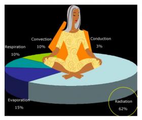
A healthy adult engaged in light activity generates heat at a rate of about 400 Btu/hr. Figure 3-1 shows the heat transfer processes by which a human adult dissipates this metabolic heat production.
Notice that a high percentage of the body’s heat dissipation comes from thermal radiation to surrounding surfaces. This has profound implications regarding comfort. It can make a person located near a large, cool surface, such as a window on a cold winter day, quite uncomfortable, even if the room’s air temperature is 70°F. The opposite is also true: the gentle warmth emitted by a heated surface, such as a warm floor or ceiling, or a panel radiator, can provide excellent comfort, even when the surrounding air temperature is in the mid-60ºF range.
Designers can assess how different building characteristics influence human thermal comfort using software called the CBE Thermal Comfort Tool.
Several types of hydronic distribution systems simultaneously influence air temperature, temperature stratification, and surface temperatures of rooms in ways that enhance human physiological comfort. This distinguishes them from alternatives such as electric furnaces, ductless mini split heat pumps, or central heat pumps that connect to forced-air distribution systems. These air-based delivery systems have less influence on interior surface temperatures and can create undesirable drafts or air temperature stratification. As such, they are not as well-matched to human comfort needs.
ACOUSTICAL COMFORT
Most people want their home to be a quiet refuge from the pace and noise of modern life. They don’t want to hear sounds emanating from their heating and cooling systems. Properly designed and installed hydronic systems using radiant panels or panel radiators can operate with virtually no detectable sound within occupied spaces. The sound produced by the source equipment, such as the compressor in a heat pump, is either outside the building or it can be acoustically isolated within a mechanical room.
Although some ducted forced-air systems can also operate at very low sound levels, the levels associated with wall-mounted fan-coils, such as used in ductless heat pumps, is clearly detectable by occupants with normal hearing. That sound, although not intense, is still undesirable. It can interfere with conversation, listening to music or watching television, especially for occupants with partial hearing loss.
REDUCED AIR VELOCITY
Most hydronic-based systems also create minimal air velocity within conditioned spaces. This reduces the possibility of drafts, which compromise comfort. Lower air velocity also reduces the dispersant of airborne pollutants such as viruses, dust, pollen, smoke, volatile organic compounds and cooking odors.
This characteristic doesn’t eliminate the need for proper ventilation, or filtration of ventilation air, such as provided by a heat recovery ventilator, but it does enhance the effectiveness of that ventilation.
EASY ZONING
Hydronic heating & cooling systems can be easily zoned to allow different spaces within a building to accommodate individual comfort preferences and activity levels. Well-planned zoning can also help eliminate overheating or underheating due to variations in internal heat gain from sunlight, appliances, lighting and occupants. This ability is especially beneficial in low-energy and net-zero buildings, which, due to their high-performance thermal envelopes, are more prone to variations in air temperature due to internal heat gains.
ELECTRIC HEATING & COOLING SOURCE EQUIPMENT
There are several electrically operated devices that can provide heating and cooling when combined with a hydronic distribution system in a low-energy or net-zero building.
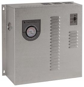
One of the simplest hydronic heat sources is an electric boiler, an example of which is shown in Figure 3-3.
Electric boilers contain one or more resistance heating elements that directly heat water passing through the boiler. For residential and light commercial systems, these boilers are available with rated heating outputs from 5 kW (17,065 Btu/hr) to 40 kW (136,500 Btu/hr).
Electric boilers suitable for use in homes or small commercial buildings are typically supplied by one or more single-phase 240 VAC circuits. When an electric boiler is being considered, it is essential to verify that the building’s electric service has sufficient capacity to operate it, in addition to the other loads. A 200-amp electric service is generally considered a minimum requirement.
All electric boilers provide one kilowatt•hour (3,413 Btu) of heat per kilowatt•hour of electrical input. That performance can also be represented as a coefficient of performance (COP) of 1.0 when comparing them to heat pumps.
Because they are electric resistance heaters, these boilers require 2 to 4 times as much electrical energy input as a heat pump (assuming heat pumps with seasonal average COPs of 2.0 to 4.0). Their operating cost relative to a heat pump will be proportional to the heat pump’s seasonal average COP (i.e., an electric boiler’s operating cost would be 3 times higher relative to that of a heat pump with a seasonal average COP of 3.0). This higher operating cost may be justified for a small, highly energy-efficient home, especially where electric rates are low or time-of-use rates are available. The relatively low installation cost of an electric boiler relative to an equivalent heat pump also helps justify their potential use in low-energy and net-zero buildings.
Advantages of electric boilers include:
- Very small and easy to mount
- No combustion or venting requirement
- Some have internal controls that regulate outlet temperature based on outdoor reset
- Much less expensive than heat pumps of equivalent heating capacity
- Can operate at elevated water temperatures up to 200ºF if necessary
- Minimal servicing requirements
Disadvantages include:
- Cannot provide cooling
- Higher operating cost relative to heat pumps of equivalent capacity
- Typically require minimum 200-amp electric service entrance
- High power draw may be beyond what a typical emergency generator can supply
To date, most of the North American systems that combine heat pumps with hydronic distribution have used water-to-water heat pumps supplied by geothermal heat sources (e.g., earth loops or water wells).
In heating mode operation, a water-to-water heat pump absorbs heat from a low-temperature geothermal source, increases the temperature of that heat, and passes it to a separate higher-temperature water stream that delivers it using a hydronic distribution system.
In cooling mode, a water-to-water heat pump absorbs heat from a stream of water that passes through one or more air handlers, fan-coils or other cooling terminal unit(s) within the building. The temperature of that absorbed heat is increased, and it is passed to another water (or antifreeze solution) stream that dissipates it outside the building — typically to an earth loop.
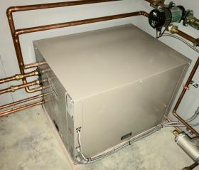
Figure 3-4 shows an example of a water-to-water heat pump having a nominal heat output of 48,000 Btu/hr.
Two of the four larger pipes connected to this heat pump go to an earth loop. The other two connect to the hydronic distribution system. The two smaller pipes near the bottom of the heat pump connect a desuperheater heat exchanger within the heat pump to a domestic hot water storage tank. All of these pipes will be insulated and vapor-sealed when the installation is completed.
Most currently available water-to-water heat pumps can produce water at temperatures up to approximately 125ºF for space heating. They can also produce chilled water for cooling.
For more information on water-to-water heat pumps, and how they can be applied in geothermal applications:
Advantages of geothermal water-to-water heat pumps include:
- Can provide heated water up to 125ºF and chilled water for cooling
- No visible outdoor equipment or sound
- Slightly higher seasonal COP compared to air-source heat pumps in cold climates
- Can be ordered with desuperheater for domestic water heating
- Longer expected service life (20-25 years) relative to air-source heat pumps due to their interior location
- No defrost cycle is required (as needed for all air-source heat pumps)
- No venting or combustion air is required
Disadvantages include:
- Significantly higher installation cost compared to air-source heat pumps
- Installation is often highly disruptive of existing landscape
- Not compatible with all installation sites due to lot size, ground water regulations, presence of rock ledge, etc.
- Antifreeze solution generally required in earth loops
Low-energy and net-zero buildings equipped with hydronic heating and cooling distribution systems can also be supplied by heat pumps that absorb heat from outside air, even when the temperature of that air is below 0ºF. This low-temperature heat is combined with electrical energy to produce a stream of heated water at temperatures up to about 130ºF. Like water-to-water heat pumps, most air-to-water heat pumps contain refrigerant reversing valves, allowing them to also provide chilled water for cooling.
Air-to-water heat pumps eliminate the need for geothermal earth loops. This allows for installation at almost any site, and at significantly lower cost compared to that of geothermal heat pump systems of equivalent capacity.
There are two primary configurations for air-to-water heat pumps:
- Monobloc
- Split system
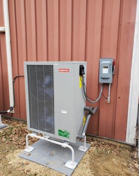
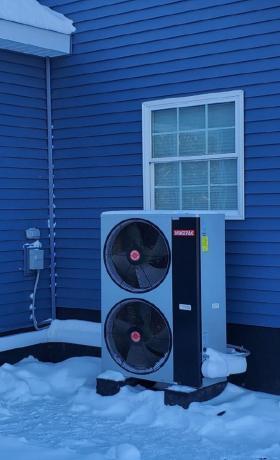
Figure 3-5 shows an example of a monobloc air-to-water heat pump.
The refrigeration system in a monobloc air-to-water heat pump is completely contained within the outdoor cabinet. It is charged with refrigerant, sealed and leak-tested before leaving the factory. Installers do not need to add to or adjust any part of this refrigeration system. They only need to run supply and return piping and electrical power to the heat pump. This allows the potential for the heat pump to be installed by a contractor who doesn’t have the experience or servicing tools to deal with refrigeration systems.
Because they are located outside in cold climates, nearly all monobloc air-to-water heat pumps operate with a mixture of water and antifreeze, such as a 30% solution of non-toxic propylene glycol. This protects the heat pump from potential freeze damage during a prolonged power outage in sub-freezing weather.
Monobloc air-to-water heat pumps also contain significantly less (approximately half) the refrigerant volume per ton of heating capacity compared to ductless heat pumps, especially when the latter are installed with the maximum allowable refrigerant line set lengths between the outdoor unit and multiple indoor units.
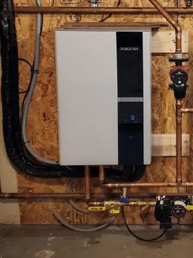
Figure 3-6a/b shows an example of a split-system air-to-water heat pump. The outdoor unit connects with the indoor unit using two copper refrigerant lines, the same as used with most central air-conditioning systems. There is no water in the outdoor unit, which eliminates the need for antifreeze in the system. The indoor unit contains the refrigerant-to-water heat exchanger, which serves as the condenser in heating mode and the evaporator in cooling mode.
Split-system air-to-water heat pumps have comparable performance to monobloc units. In heating mode, both operate over a range of heating capacity and COPs depending on the outdoor air temperature and the leaving water temperature at which they are operating. Both are available with variable-speed, “inverter-driven” compressors that allow them to vary heating and cooling capacity from some maximum rated output down to about 30 percent of that output. This is helpful in situations where a single-zone, chilled-water cooling distribution unit needs to operate at a relatively small capacity compared to the heat pump’s full heating capacity.
Advantages of air-to-water heat pumps include:
- Can provide heating water up to 130ºF and chilled water for cooling
- Can be installed at nearly all sites
- Not disruptive to landscaping
- Low ambient units can operate at sub-0ºF air temperatures
- Significantly lower installed cost relative to equivalent geothermal heat pumps
Disadvantages include:
- Shorter expected service life (15-20 years) due to outside installation
- Slightly higher operating cost relative to geothermal water-to-water heat pumps
- Automatic defrost cycles are required
- Monobloc systems require antifreeze in outdoor piping
- Limited availability of units with desuperheater for domestic water heating
- Highly zoned systems will require a buffer tank
For more information on air-to-water heat pumps, see
DISTRIBUTION EFFICIENCY
Professionals who design low-energy and net-zero buildings apply scrutiny when selecting the
“source equipment” that supplies space heating, cooling and domestic hot water. They often limit selections to state-of-the-art devices with the highest available thermal efficiencies.
While this approach is certainly relevant and logical, it is also incomplete. The energy used by the source equipment, be it a boiler, heat pump or chiller, is only part of the total energy used by the system. Regardless of how heating energy or cooling effect is generated, additional energy is needed to distribute that thermal energy within a building. Treating this “distribution energy” as insignificant or inconsequential is a serious oversight in the design process, especially when the objective is to create buildings that minimize energy use.
The energy required to distribute heat produced by any heat source, or the cooling effect generated by any cooling source, should always be considered when designing a heating or cooling system for a low-energy or net-zero building. Systems that use a significant amount of energy to move heat from where it is produced to where it is needed in the building are undesirable, even if the thermal energy is produced at high efficiency by the source equipment.
Distribution energy is an even more important consideration for cooling systems. Every watt of electrical energy used to move cooling effect through a building is a watt added to the building’s sensible cooling load. For example, a constant-torque ECM blower motor used in a nominal 3-ton forced-air heat pump adds about 2,935 Btu/hr (0.24 tons) to the building’s sensible cooling load. An ECM circulator delivering an equivalent cooling effect using chilled water, and operating at an input power of 35 watts, only adds 120 Btu/hr to the sensible cooling load.
Designers should also consider that air-to-air heat pumps typically require higher air flow rates per unit of heat delivery compared to fossil-fuel furnaces, and thus their distribution power requirement is higher, assuming the same blower motor technology in each device.
One way to assess this aspect of system design is through an index called “distribution efficiency,” which is defined as follows: $$ n_d = {Q_{delivered} \over {w_e}} $$
Where:
$Q_{delivered}$ = rate of heat delivery under design load conditions (Btu/hr)
$w_e$ = electrical power required by the distribution system under design load conditions (watts)
The higher the distribution efficiency, the lower the operating cost of the distribution system per unit of heat delivered.
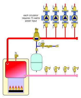
For example, consider a “traditional” hydronic heating system that uses four small circulators, each operating on 75 watts input power, and collectively delivering 100,000 Btu/hr to the building. A schematic of this system is shown in Figure 3-7.
Assuming that all circulators are operating under design load conditions, the distribution efficiency would be: $$ n_d = {Q_{delivered} \over {w_e}} = {100,000{{Btu} \over hr} \over {4 \times 75watt}} = 333.3{ {Btu\ /\ hr} \over {watt}}$$
The number 333.3 Btu/hr/watt can be interpreted as follows: for each watt of electrical power supplied to the distribution system, it delivers 333.3 Btu/hr to where it’s needed in the building.
However, this number has little relevance without something to compare it to. To provide such a comparison, consider a forced-air delivery system associated with a furnace that requires 550 watts while delivering 80,000 Btu/hr to the building. The distribution efficiency of that system is: $$ n_d = {Q_{delivered} \over {w_e}} = {80,000{{Btu} \over hr} \over {550watt}} = 145.5{ {Btu\ /\ hr} \over {watt}} $$
In this specific comparison, the forced-air system has less than half the distribution efficiency of the hydronic system. This implies that the forced-air system requires over twice the electrical power input of the hydronic system to deliver the same amount of heat to the load.
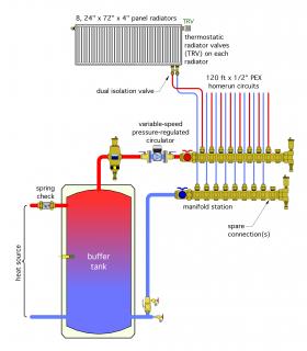
The concept of distribution efficiency can be used to compare hydronic versus forced-air heating systems, as well as competing hydronic system designs. Consider, for example, the contemporary “homerun” hydronic distribution system as shown in Figure 3-8.
This system, which would be well-suited for use in low-energy or net-zero homes, uses a high-efficiency variable-speed pressure-regulated circulator to create flow between the buffer tank and 8 individually regulated panel radiators. Under design load conditions, the water leaving the buffer tank is maintained at 120ºF, which is well within the operating range of an air-to-water or water-to-water heat pump.
Each panel radiator is assumed to be piped with 1/2-inch PEX tubing, 60 feet out and 60 feet back from a manifold station. A non-electric thermostatic radiator valve regulates the flow of warm water through each panel radiator based on its setting and the current room temperature.
A hydraulic analysis of this system, under the stated conditions, shows that it could deliver 30,800 Btu/hr to a building, with a circulator power input of only 8.6 watts. Thus, it would have a distribution efficiency of:
$$ \color{maroon}{\text{distribution efficiency} = {30,800{{Btu} \over hr} \over {8.6watt}} = 3581{ {Btu\ /\ hr} \over {watt}}} $$
Comparing this to the previously discussed forced air distribution system, which had a distribution efficiency of 145 Btu/hr/watt, shows that this modern hydronic system can deliver heat to the building using only (145/3581) = 4% of the electrical input energy needed by the forced-air system, per unit of heat delivered. This demonstrates the overwhelming advantage of using water, rather than air, in combination with state-of-the-art hydronic hardware, to deliver heat in a low-energy or net-zero building.
Assuming that the high-efficiency circulator operated at approximately 75 percent of design input wattage for 3,000 hours per year, in a location where electricity costs \$0.12/kW/hr, the seasonal operating cost of the distribution system would only be about \$2.32. This compares to a seasonal estimated operating cost of $148 for the previously described forced-air system operating under the same assumed conditions.
MINIMALLY INVASIVE INSTALLATION
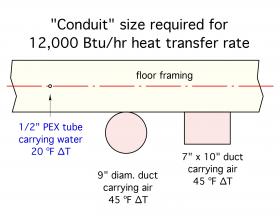
A given volume of water can absorb almost 3,500 times more heat than the same volume of air, assuming both materials undergo the same temperature rise. This allows a given rate of heating or cooling to be conveyed using small diameter hydronic tubing relative to the size of a duct conveying that same rate of heat transport using air.
For example, consider a heat transfer rate of 12,000 Btu/hr. This would be adequate to heat an area of 1,200 square feet in a low-energy or net-zero house having a design load of 10 Btu/hr/ft2 of floor area. If water is used to convey this heat transfer, and the hydronic distribution system operated at a typical design load temperature drop of 20ºF, the required flow rate is only 1.2 gallons per minute (gpm). This flow rate could be handled by a nominal 1/2-inch PEX tube. That tube could be easily routed along or through framing members with virtually no impact on the structure.
If air is used to provide this same 12,000 Btu/hr heat transport rate, while undergoing a temperature change from 65ºF to 110ºF through the heat source, the required flow rate would be 247 cubic feet per minute (CFM). Assuming a typical duct sizing air velocity of 600 feet per minute (FPM), a 9-inch diameter round duct, or a 7-inch high by 10-inch wide rectangular duct would be needed. Figure 3-9 shows a scaled comparison of these different delivery “conduits.”
A 1/2-inch PEX tube could be easily routed through floor framing using 3/4- or 7/8-inch diameter holes. If these holes were drilled near the center of the floor joists, they would have no significant impact on the structure. However, due to their size, the equivalent ducts shown would have to be supported under the floor framing, potentially compromising the use of the space below.
Beyond the heat conveyance consideration is the issue of heat loss and possible insulation requirements. A 9-inch diameter duct has about 14 times more surface area compared to a 1/2-inch PEX tube. The 7-inch by 10-inch rectangular duct shown in Figure 3-9 has about 17 times more surface area. Assuming the same insulation requirement, the round duct would require about 14 times more insulation material, and the rectangular duct about 17 times more material, per unit of length. If the ducting and hydronic tubing operated at the same temperature, the heat loss (or heat gain in cooling mode) would be substantially higher for the ducting.
REFRIGERANT CONSIDERATIONS
Nearly all monobloc-style air-to-water heat pumps and geothermal water-to-water heat pumps used in hydronic heating and cooling systems come with a factory-charged, sealed and leak-tested refrigeration system. With proper handling and installation, the chances of a refrigerant leak occurring during or after installation are very small.
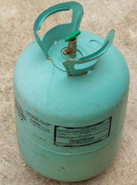
A small 2-ton rated monobloc heat pump contains about 5 pounds of refrigerant. A 5-ton rated unit would contain about 7 pounds. These relatively small refrigerant volumes should be compared to those of multi-head ductless heat pumps and commercial VRF systems.
One nominal 3-ton ductless heat pump system, when applied with maximum allowable refrigerant piping lengths, requires approximately twice the refrigerant volume per ton of rated capacity compared to that required by a typical factory-sealed air-to-water or water-to-water heat pump. One 8-ton rated VRF system contains over 25 pounds of refrigerant, more
than twice the volume of refrigerant per ton of capacity compared to a typical factory-sealed air-to-water or water-to-water heat pump.
Large VRF systems in commercial buildings can contain hundreds of pounds of refrigerant. A leak in such a system is a serious safety issue, as well as an environmental hazard. Although the currently popular refrigerant R-410a is not toxic and non-flammable, it will displace air if allowed to accumulate within a confined space. Given sufficient concentration and the inability to vacate a space quickly, this could lead to asphyxiation.
One OSHA material safety data sheet (MSDS) for R-410a states the following: “In Case of Spill or Leak Use Halogen leak detector or other suitable means to locate leaks or check atmosphere. Keep upwind. Evacuate enclosed spaces and disperse gas with floor-level forced-air ventilation. Exhaust vapors outdoors. Do not smoke or operate internal combustion engines. Remove flames and heating elements.”
ASHRAE Standards 15 and 34 set specific limits on how much refrigerant a system can contain based on the volume of the smallest interior space into which that refrigerant could potentially leak. Under ASHRAE Standard 34, which applies to systems containing more the 6.6 pounds of refrigerant, there can be no more than 26 pounds of refrigerant in the system per 1,000 cubic feet of the smallest occupied space into which refrigerant could potentially leak. For institutional buildings, where occupants might not be able to evacuate without assistance, the limit is 13 pounds of refrigerant per 1,000 cubic feet of smallest occupied space.
Ductless heat pumps and VRF systems also contain many site-fabricated joints in refrigeration piping. Most of these joints are inside the building. Figure 3-11 shows both brazed and compression joints in refrigeration tubing that’s a small portion of a VRF system installed at a multi-story hotel.
Although field-installed refrigerant piping is leak-tested during the installation, the number of connections and the conditions under which they are made inevitably increase the possibility of leaks over time.
Another consideration is the ongoing evolution of refrigerants based on their global warming potential. Prior to the 1990s, the most common refrigerant used in North American heat pumps and central air-conditioning systems was R-22, which, among other compounds, contained chlorine. Rising concern over the effects of chlorine on atmospheric ozone eventually led to a phaseout of R-22. Beginning in January 2020, the production or import of R-22 was no longer allowed in the U.S.
Today, most residential and light commercial heat pumps and air-conditioning systems used in North America operate on R-410a refrigerant. However, due to its global warming potential relative to newly developed alternative refrigerants, R-410a is also scheduled to be eliminated from new equipment beginning in January 2023. There will likely be a multi-year phaseout plan for R-410a similar to that used for R-22. New refrigerants such as R-32, which has a lower global warming potential (roughly 1/3 that of R-410a), are already being used in some new heat pumps systems in Europe and Asia. Eventually, propane (R-290), which has good refrigerant properties and low global warming potential, may be accepted for use as refrigerant in some heat pump applications where all the refrigerant remains in outdoor equipment. However, it remains questionable whether a flammable refrigerant, such as propane and to a lesser degree (R-32), would be allowed in systems with large refrigerant volumes and extensive interior refrigerant piping. This situation has the potential to severely limit the future service of current-generation VRF systems.
Beyond specific refrigerant chemistries are potential compatibility issues related to lubricating oils, and the size/pressure rating of the refrigerant piping used. The latter consideration is especially relevant to large VRF systems, which can contain thousands of feet of copper tubing selected and sized for specific current-generation refrigerants and their associated lubricants.
These considerations should be contrasted with those relevant to the air-to-water or water-to-water heat pumps used with hydronic distribution systems. Monobloc air-to-water heat pumps contain all refrigerant outside the building. As such, they are more adaptable to potential use with flammable refrigerants. The relatively small refrigerant volumes present in these heat pumps in comparison to those present in VRF systems makes the consequences of a leak much less costly, and less of a safety issue.
Buildings equipped with hydronic heating and cooling distribution systems are also minimally dependent on evolving refrigerant regulations — provided the source equipment using these refrigerants can meet the capacity and supply water temperatures required by the hydronic distribution system.
PIPING FLEXIBILITY
There are several piping configurations that have been used for hydronic heating and cooling systems over many decades. These configurations are highly scalable. In smaller systems, the piping is typically sized so that flow velocities don’t exceed 4 feet per second. The orientation of the piping in a closed hydronic system is largely irrelevant — provided that provisions are made to vent air from high points in the system. Piping can be vertical, horizontal, sloped and routed over or under obstructions. Different piping materials, such as copper, steel, PEX and polypropylene, can be combined in the same system when there are advantages in doing so.
In contrast, the piping requirements for VRF system are much more restrictive. Very specific details are required to prevent oil, which is circulated through the system with refrigerant, from being trapped and thus unable to flow back to the compressor. Insufficient oil return has resulted in compressor failures, which can cost thousands of dollars to isolate, replace and recommission. Most VRF systems are also limited to copper tubing.
VERSATILITY OF HYDRONIC SYSTEMS
Although it’s likely that heat pumps will steadily gain market share against fossil-fuel boilers in the years ahead, it’s unlikely that the fossil-fuel boiler market will suddenly disappear. Existing fossil-fuel boilers will, in most cases, remain in operation until they can no longer be serviced, or until the cost of the fuel they require becomes significantly more expensive on a $/MMBtu basis compared to heat supplied through other means.
This can be beneficial, especially as a step in transitioning existing buildings from fossil fuel to an all-electric status. An existing boiler can serve as an auxiliary heat source as well as a peak load heat source, in combination with an electrically powered heat pump that serves as the primary heat source. In such a system, the objective is to provide heat from the heat pump whenever possible, but also recognize that some heat pumps may not have the heating capacity or be able to produce suitably high water temperatures to meet the building’s heating load on extremely cold days. Making use of an existing boiler can also reduce the cost of the installation relative to removing an otherwise functional boiler and replacing it with a heat pump sized to cover the building’s design heat load.
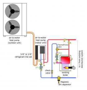
Figure 3-12 shows a relatively simple way to incorporate an existing boiler along with a new air-to-water heat pump. The partial system shown in Figure 3-12 has a split-system air-to-water heat pump piped in parallel with the existing boiler. Each heat source has its own circulator. There is also a check valve associated with each heat source to prevent flow reversal when that heat source is off and the other one is operating.
The controls for the system may be internal to the heat pump, or possibly external to either heat source, depending on the specific equipment used. The objective of the controls, during heating mode operation, is to use heat from the heat pump whenever possible, but invoke operation of the boiler when necessary to ensure that the load is being met. The boiler would typically be called to operate if the heat pump is unable to maintain some pre-set temperature on the supply side of the distribution system.
During cooling mode, the boiler would remain off. The heat pump would be operated as necessary to provide a suitable chilled-water supply temperature to the remainder of the system.
One way to maximize the seasonal COP of a heat pump supplying a hydronic distribution system is to regulate the supply water temperature based on outdoor reset control. This control strategy, which is built into the internal controls of some modern heat pumps, only allows the water temperature produced by the heat pump to be high enough to meet the current heating load. During mild weather, the water temperature supplied by the heat pump would be automatically lowered to maximize the heat pump’s coefficient of performance (COP). As the load increases, the water temperature supplied by the heat pump would increase, up to a maximum of 125ºF to 130ºF. If higher supply water temperatures are needed, the heat pump would be turned off and the boiler would supply the load.
Depending on its heating capacity relative to the building’s design load and the climate, an air-to-water heat pump or geothermal water-to-water heat pump may be able to supply 75 percent or more of the building’s seasonal space heating energy, even when connected to a legacy hydronic distribution system using “high-temperature” heat emitters, such as fin-tube baseboard.
This percentage of total seasonal space heating energy can be increased by either reducing the building’s heating load, or by adding heat emitters to the system. Both of these techniques lower the required water temperature of the distribution system. In some cases, an air-to-water heat pump can provide upwards of 95 percent of the seasonal space heating energy.
For more information and details on lowering water temperature in existing hydronic distribution systems: idronics #25
The boiler shown in Figure 3-12 is assumed to be an existing “conventional” boiler (e.g., one not intended to operate with sustained flue gas condensation). When outdoor reset control is added to the system, there will be times when the water temperature is significantly lower than temperatures associated with the original installation. A Caleffi ThermoProtect mixing valve should be installed to protect the existing boiler for operating with sustained flue gas condensation.
The existing boiler can also serve as a low-power-demand backup heat source during a power outage. Most residential-sized gas-fired or oil-fired boilers can operate with an electrical power demand in the range of 100 to 400 watts. By comparison, a residential-sized heat pump may have a power demand in the range of 2,000 to 6,000 watts. The relatively low power demand of the exiting boiler could be supplied by a small emergency generator. It might also allow the boiler to operate from the home’s electrical energy storage system — if so equipped. This concept demonstrates a degree of resiliency that might not be possible with an electric boiler due to its much higher electrical power demand.
If the building is eventually converted to all-electric as part of a net-zero strategy, the existing boiler could be replaced by an electric boiler with minimal piping modifications. However, this should only be done after an evaluation of the building’s electrical service entrance to ensure adequate capacity. It might also entail an upgrade to the building’s emergency generator if that generator is expected to power the electric boiler.
THERMAL STORAGE POTENTIAL
Water is one of the best materials available for storing thermal energy. This characteristic allows hydronic systems to include thermal energy storage where it provides a benefit. One possibility that’s applicable in areas where utilities offer time-of-use electrical rates is operating a heat pump or an electric boiler during “off-peak” times when the cost of electricity is significantly reduced, and store some of the thermal energy produced during this period in an insulated tank for use during “on-peak” periods. Another possibility is to store heat produced by an electric boiler or heat pump during “off-peak” times in a large, solid, thermal mass such as a thick concrete slab with embedded hydronic tubing. Both of these techniques have been used in limited applications to date. They hold potential for increased adaptation as influencing factors such as real time electrical pricing become more common. Air-based heat pump systems have virtually no ability to leverage these opportunities without significantly and detrimentally affecting comfort. Thermal storage can also be coordinated with chilled-water cooling systems.
EASY EXPANDABILITY
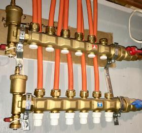
There are several ways that hydronic heating and cooling systems can be designed for easy future expansion. This is especially true for homerun distribution systems supplying panel radiators or fan-coil units. A manifold station, such as that shown in Figure 3-13, can be installed with one or more extra connections to allow heat emitters to be easily added.
Another possibility is to pipe systems during initial installation so that a second air-to-water heat pump could be added in the future to significantly increase heating or cooling capacity. By comparison, most central air-to-air heat pumps and ductless heat pump systems used in residential and light commercial applications do not allow for expansion beyond the configuration in which they were originally purchased. For example, a ductless system that was ordered in a 4-zone configuration could be initially used with 3 zones, but it could not be expanded to 5 zones. Any addition or modification to the building that required a 5th zone would require either a new condenser unit with 5 zones, or a separate single-zone system. Furthermore, multi-zone ductless heat pump systems are restrictive in terms of manufacturer-approved combinations of specific outdoor and indoor units.
ALL LOADS FROM A SINGLE HEAT PUMP
Another unique possibility offered by hydronic systems is the ability to provide domestic water heating in addition to space heating and cooling, all from the same heat pump. In a modern low-energy home, domestic water heating often represents 25 to 30% of the total thermal energy used and is therefore a major consideration if attempting to reach net-zero status. Domestic water heating is typically not provided by central air-to-air heat pumps or ductless heat pump systems.
Traditional approaches to domestic water heating in all-electric homes include electric resistance heating elements in a tank or within a tankless “on-demand” heater. Both of these approaches have been successfully used in thousands of buildings, some of which were likely achieving net-zero status.
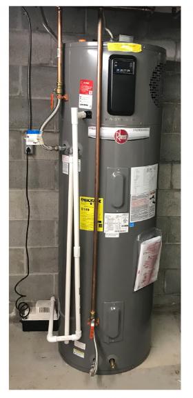
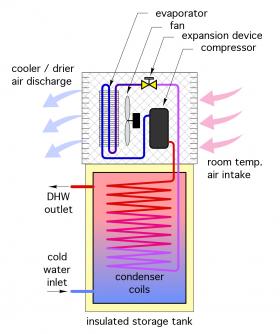
A more recently introduced option — the heat pump water heater — is attracting the attention of some designers involved with net-zero buildings. These water heaters use a simple vapor/compression refrigeration cycle to gather heat from surrounding air and transfer it to domestic water in an insulated tank. Figure 3-14 shows a typical heat pump water heater installation and representative schematic of its refrigeration system.
Heat pump water heaters are well-suited to situations where “surplus” heat is available inside, or in some cases, outside a building. When properly applied, they can provide domestic hot water using roughly 1/3 the electrical energy required by electric resistance water heaters.
However, the term “surplus heat” must be scrutinized. Fundamentally, it implies that the low-temperature heat absorbed by the heat pump water heater is present due to circumstances other than being created by the building’s heating system. Examples of such circumstances include low grade heat in outdoor air, excess solar heat gains inside a building, low grade heat in an unconditioned basement or garage, or heat generated by equipment or processes in a commercial building. These sources of heat are a byproduct of how the building is configured or used, rather than heat intentionally produced by the building’s heating system. This is an important distinction because the “net” efficiency (measured as net COP) of a heat pump water heater that absorbs heat created by the building’s heating system is significantly lower than that of one that absorbs “surplus” heat.
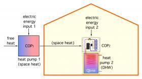
Figure 3-15 shows the concept of “cascading” heat pumps (e.g., where the heat pump water heater absorbs heat placed in its vicinity it by another heat pump).
Heat pump 1 is absorbing free heat from outside the building, combining it with heat derived from electricity, and sending that heat inside the building. Heat pump 2 is a heat pump water heater. The water heater absorbs heat that was placed inside the building from heat pump 1, combines it with more energy sourced from electricity, and sends combined energy into domestic water within the tank.
The net COP of this cascading heat pump system can be determined as follows:
$$ COP_{net} = \color{blue}{{ \Bigl({COP_1 \over COP_1-1} \Bigl) \Bigl( {COP_2 \over COP_2-1} \Bigl)} \over \color{red}{{ \bigg[} \color{blue}{ \Bigl({COP_1 \over COP_1-1} \Bigl) \Bigl({COP_2 \over COP_2-1} \Bigl) -\color{red}{1}}} \color{red}{\bigg]}} $$
Where:
$COP_{net}$ = the overall COP of the two cascaded heat pumps
$COP_1$ = the COP off the space heating heat pump (must be > 1.0)
$COP_2$ = the COP of the heat pump water heater (must be > 1.0)
Note: To use this formula, both $COP_1$ and $COP_2$ must be > 1.0
For example, if a heat pump provides space heating to a building while operating at a COP of 4.0, and a heat pump water heater within that building only absorbed heat produced by the space heating heat pump while operating at a COP of 3.0, the net COP, defined as the heat added to the domestic water divided by the total electrical input to enable that heat placement, would be:
$$ COP_{net} = \color{blue}{{ \Bigl({COP_1 \over COP_1-1} \Bigl) \Bigl( {COP_2 \over COP_2-1} \Bigl)} \over \color{red}{{ \bigg[} \color{blue}{ \Bigl({COP_1 \over COP_1-1} \Bigl) \Bigl({COP_2 \over COP_2-1} \Bigl) -\color{red}{1}}} \color{red}{\bigg]}} = \color{blue}{{ \Bigl({4 \over 4-1} \Bigl) \Bigl( {3 \over 3-1} \Bigl)} \over \color{red}{{ \bigg[} \color{blue}{ \Bigl({4 \over 4-1} \Bigl) \Bigl({3 \over 3-1} \Bigl) -\color{red}{1}}} \color{red}{\bigg]}} = {2 \over 2- \color{red}{1}} = 2.0 $$
A net COP of 2.0 means that for every two units of heat delivered to the domestic water, one came from a “free” source, and the other came as electric heating. Although this net COP is still double the COP of any form of electric resistance heating (e.g., COP = 1.0), it is far lower than the rated COP of the heat pump water heater operating under the assumed condition of absorbing “free” surplus heat. In most buildings, there will be times when the heat absorbed by the heat pump water heater is indeed surplus heat, and thus the long term net COP will likely be higher than the above calculation asserts. Still, the concept of “cascading heat pumps” demonstrates that placing a heat pump water heater within the heated thermal envelope of a low-energy or net-zero building, where the majority of the heat it absorbs is present due to operation of a space heating heat pump, doesn’t yield the savings often cited for heat pump water heaters.
When a single air-to-water or geothermal water-to-water heat pump provides space heating, cooling, and domestic water heating, the heat it absorbs during the domestic water heating mode is always coming from a “free” source (e.g., outside air or heat in the earth). This avoids the derating effect just described for a cascading heat pump installation. An air-to-water heat pump that supplies a year-round domestic water heating load can typically achieve annual average COPs in the range of 2.5 to 3.0, depending on climate and the temperature to which the domestic water needs to be heated.
Some air-to-water and geothermal water-to-water heat pumps also can be ordered with a desuperheater heat exchanger for domestic water heating. During cooling mode operation, the heat gathered by the desuperheater from the hot refrigerant discharged from the heat pump’s compressor is heat that would otherwise be dissipated outside the building (e.g., to outside air or into the earth). This scavenged heat is truly “free.”
When an air-to-water heat pump is operating in cooling mode, and the thermostatic control in the domestic water storage tank calls for heating, the heat pump will temporarily switch to heating mode, quickly bring the tank temperature up to its setpoint, and then switch back to cooling. Later sections will show other system configurations that use heat pumps to supply domestic hot water as well as space heating and cooling.
RESILIENCY
Many professionals who plan buildings or HVAC systems are being asked to incorporate “resiliency” into their designs. This term implies an ability for buildings, or systems within buildings, to withstand unexpected events such as extended power outages, the effects of climate change or interruption of normal supply chains. The objective is to create buildings and systems that are reliable, long-lasting, adaptable and easy to repair when necessary. Although it would be flippant to simply state that any hydronic heating or cooling system is highly “resilient,” these systems do have characteristics that fit the objectives of resiliency.
One characteristic is that there are many potential sources for much of the hardware used in hydronic heating and cooling systems. For example, the eventual failure of a specific make and model of circulator within a hydronic system, or even the inability to obtain a new circulator of the same make and model, doesn’t render the system inoperable for long. Several other makes and models of circulators are readily available for replacing the failed circulator. Most of the potential replacements would have the same flange-to-flange dimension as the original circulator, and could be installed within a few minutes by any competent heating technician using basic tools. This same concept holds true for many other components in a hydronic system, such as pipe, fittings, valves, expansion tanks, heat emitters, manifolds, air/dirt separators and basic temperature controllers, etc.
This adaptability may not be possible for alternatives such as ductless heat pumps or commercial VRF systems. Many of these systems have proprietary controls or other components that must be replaced with exactly the same component obtained from the original manufacturer or their authorized agent at whatever pricing they choose to set. Special tools, software and training are often required to fully service these systems. The eventual discontinuation of proprietary components, or long delays in obtaining them due to supply chain disruption, could render the entire system inoperable for extended periods, or even unrepairable.
Consider the following (real) scenario: A crack forms in a small plastic condensate collection pan inside a highwall fan-coil that’s part of a ductless heat pump (or VRF) system. This causes condensate to leak from the unit. Some makes and models of these fan-coil units do not allow that simple and inexpensive pan to be removed in the field and replaced as a separate component. The entire wall mounted fan-coil unit must be replaced. Doing so requires the system to be turned off. The refrigerant must be reclaimed and eventually reinstalled using specialized equipment. It also requires the refrigerant piping and wiring to be disconnected and reconnected. The overall process could take several hours and cost multiple hundreds of dollars. The fan-coil with the cracked condensate pan will likely be discarded, even though the majority of the components within it are in working order. This true story demonstrates vulnerability rather than resiliency.
Another reason that hydronic systems offer resiliency is that water will always be available as the working fluid. It is not subject to evolving global warming directives, refrigerant phaseouts, manufacturing limitations or material handling and transportation regulations. Any water lost from the system due to maintenance or component replacement is easily and inexpensively replaced. The heat source or cooling source within a hydronic system may change over time, but the physical properties that enable water to efficiently convey heat or cooling effect will not change.
Finally, most of the components used in a properly designed, installed and maintained hydronic distribution system will last for many decades. They will outlast the system’s initial heat source or cooling source, and perhaps even its second or third heat source or cooling source. Simply stated: Properly executed hydronic systems are long-term investments rather than “throw away” technology. Contrast this with the typical service life of many modern appliances, such as refrigerators, washing machines and microwaves, some of which will not even last ten years under normal service. Portions of those discarded appliances will inevitably end up in landfills.
Professionals who plan low-energy and net-zero buildings, or place emphasis on decarbonization, environmentally conscious design, and resiliency, should carefully consider these benefits associated with hydronic heating and cooling systems.

