The thermal performance of heat exchangers is very dependent on the physical properties of the two fluids passing through them. It’s also dependent on the “dynamic condition” of those fluids. The latter refers to the flow direction, velocity and degree of turbulence present in the fluids exchanging heat.
LAMINAR vs. TURBULENT FLOW
It’s helpful to imagine liquids flowing through pipes or along the surface of a plate as a stream containing millions of tiny buoyancy-neutral “particles.” The path that any one of these particles takes as it moves is called a streamline.
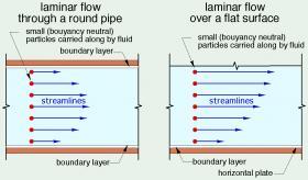
In some situations, the streamlines of all the fluid particles are parallel to each other, like multiple lanes of traffic on a major highway. The particles near the center of the pipe, or those farther away from a flat surface, move faster than those near the pipe wall or the flat surface, but they don’t “change lanes.” This type of fluid movement, represented by Figure 4-1, is called laminar flow.
Laminar flow can be desirable or undesirable depending on where it occurs in hydronic systems, as well as the intended purpose of those systems. If the goal is to move fluid long distances with minimal pumping power, laminar flow is desirable because it reduces pumping power.
However, if the goal is to maximize heat transfer from a flowing fluid, laminar flow is very undesirable. Because the fluid particles move in parallel streamlines during laminar flow, there is very little mixing between them. This increases the thickness of the boundary layer between the bulk of the fluid stream and the wall of the pipe or surface of a plate. Thicker boundary layers decrease convective heat transfer.
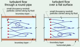
Turbulent flow causes the streamlines of the imaginary fluid particles to bend and twist as the fluid moves down the pipe or along a surface, as shown in Figure 4-2.
The erratically shaped streamlines present during turbulent flow create good mixing. A small quantity of fluid that’s close to a solid surface one instant, can be swept into the bulk of the fluid stream the next instant. This decreases the boundary layer thickness and significantly improves convective heat transfer.
The convective heat transfer associated with a relatively viscous liquid at low temperatures, such as a 25% solution of propylene glycol antifreeze at 30ºF, under laminar flow is only about 7% of the convective heat transfer of the same fluid under turbulent flow. This implies that laminar flow will result in a very significant drop in heat transfer between a fluid and the inner wall of a tube or the surface of a plate. Such a change could have a major negative effect on the ability of a hydronic circuit, such as a ground loop heat exchanger supplying a geothermal heat pump, to transfer heat at the required rate.
Although turbulent flow improves convective heat transfer, it also increases head loss, and thus requires more pumping power to maintain a given flow rate relative to the power required for laminar flow. However, the increased heat transfer capabilities of turbulent flow often far outweigh the penalty associated with the increased pumping power. Thus, when possible, all heat exchangers should be operated with turbulent flow of both fluids.
REYNOLDS NUMBER
It’s possible to predict if flow through a pipe or across a smooth plate will be laminar or turbulent. It’s based on calculating a dimensionless quantity called the Reynolds number of the fluid (abbreviated as $Re\#$).
The Reynolds number is a ratio of the inertial forces existing in a flow stream compared to the viscous forces in that flow stream. It takes several physical characteristics of the flowing fluid into account, including the fluid’s density and viscosity, both of which are dependent on the fluid’s temperature. It also accounts for the speed of the fluid and the geometry of surfaces in contact with the fluid.
When the Reynolds number is low, the inertial forces are relatively weak compared to the viscous forces. Any disturbance to the flow stream that might otherwise induce turbulence is quickly dampened out by viscous forces, and thus sustained turbulence cannot exist. However, when the inertial forces become dominant over the viscous forces, which would be characterized by higher Reynolds numbers, the dampening effects of viscosity are not able to prevent turbulent flow from being established and maintained.
For flow through a round pipe, the $Re\#$ is calculated using Formula 4-1.
Formula 4-1: $$ Re\# = {vdD \over \mu } $$
Where:
$v$= average flow velocity of the fluid (ft/sec)
$d$ = internal diameter of pipe (ft)
$D$ = fluid’s density (lb/ft3)
$\mu$ = fluid’s dynamic viscosity (lb/ft/sec)
If the Reynolds number of flow through a round pipe is over 4,000, the flow will be turbulent. If the $Re\#$ is below 2,300, the flow through the pipe will be laminar. If the $Re\#$ is between 2300 and 4000, the flow could be either laminar or turbulent, and it could switch back and forth.
Here’s an example: Determine the Reynolds number of water at 140°F flowing at 5 gpm through a 3/4-inch type M copper tube. Is this flow laminar or turbulent?
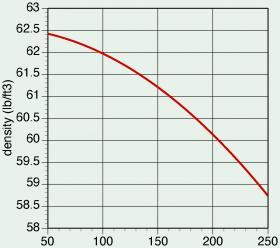
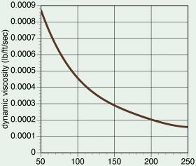
Solution: To calculate the $Re\#$, the density and dynamic viscosity of the water must be determined. The density of water can be found from Figure 4-3. The dynamic viscosity of water can be found from Figure 4-4.
At 140ºF, the density of water is read from Figure 4-3 as 61.35 lb/ft3. From Figure 4-4, the dynamic viscosity of water at 140ºF is 0.00032 lb/ft/sec.
The inside diameter of a 3/4-inch type M copper tube is 0.811 inches. This must be converted to feet to match the stated units for Formula 4-1:
$$ d = (0.811 \ in) \left( 1 \ ft \over 12 \ in \right) = 0.06758 \ ft $$
The average flow velocity corresponding to a flow rate of 5 gpm can be found using Formula 4-2.
Formula 4-2: $$ v = \left( 0.408 \over d^2 \right) f $$
Where:
$v$ = average fluid velocity (ft/sec)
$d$ = exact inside diameter of pipe (inches)
$f$ = flow rate through pipe (gpm)
For 3/4-inch Type M copper tubing operating at a flow rate of 5 gpm, the average flow velocity is: $$ v = \left( 0.408 \over d^2 \right) f = \left( 0.408 \over (0.811)^2 \right)5 = 3.1{ ft \over \text{sec} } $$
The Reynolds number can now be calculated using Formula 4-1. $$ Re\# = {\left(3.1{ ft \over \text{sec} } \right)(0.06758 \ ft) \left( 61.35 {lb \over ft^3} \right) \over 0.00032{lb \over ft \ \cdot \ \text{sec} }} = 40,165 $$
This value is well above the 4,000 threshold and therefore the flow is turbulent.
Notice that the units on the quantities used in Formula 4-1 cancel out completely. A valid Reynold number must always be a number — with no units, regardless of the use of the IP or SI unit system. When calculating a Reynolds number, it is good practice to enter the units on all quantities and be sure they all cancel out.
From a practical standpoint, most flows in hydronic heating and cooling systems will have $Re\#$ well above 4,000, and thus be turbulent. The higher the $Re\#$, the more intense the turbulence. Flows through any device that adds or removes heat from a fluid (e.g., any heat exchanger, hydronic heat emitter or cooling coil) should always be turbulent.
FLOW DIRECTION THROUGH HEAT EXCHANGER
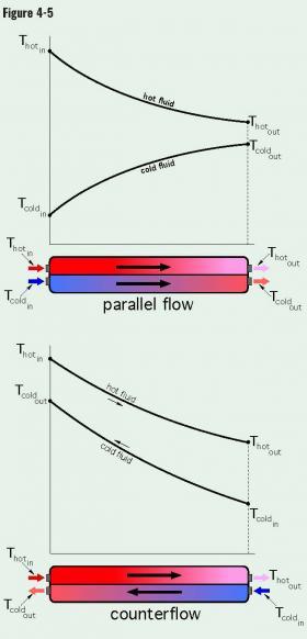
The liquid-to-liquid heat exchangers used in hydronic systems are configured so that the two fluid streams flow in mostly parallel directions to each other. The two parallel streams could be flowing in the same direction or in opposite directions. When the two streams flow in the same direction, the configuration is called “parallel flow,” or sometimes “cocurrent” flow. When the two flow streams flow in opposite directions, the configuration is called “counterflow.” These two flow configurations, along with representative temperature changes of both fluid streams, are shown in Figure 4-5.
One of the fundamental characteristics of heat exchangers is that the rate of heat transfer depends on the temperature difference between the fluid providing the heat and the fluid absorbing that heat. The greater this temperature difference, the higher the rate of heat transfer.
It’s apparent that the temperature difference between the hot fluid and cool fluid in the heat exchangers represented in Figure 4-5 varies considerably depending on the location within the heat exchanger where this difference is measured. For the parallel flow heat exchanger, the temperature difference at the left side, where both fluids enter, is very large. But this temperature difference decreases rapidly as the fluids exchange heat and move toward the outlet ports. There’s also a variation in the temperature difference between the fluids as they move through the counterflow heat exchanger.
To evaluate the rate of heat transfer across the entire heat exchanger, it is necessary to establish an “average” temperature difference. This average temperature difference could be defined as a value that if present at all locations that separate the fluids within the heat exchanger would result in the same overall heat exchange rate as will occur given the actual and highly variable temperature differences.
Heat transfer theory can be used to derive this “average” $(\Delta T)$. It’s called the log mean temperature difference ($LMTD$) and can be calculated using Formula 4-3.
Formula 4-3: $$ LMTD = { (\Delta T)_1 - (\Delta T)_2 \over ln \left[ (\Delta T)_1 \over (\Delta T)_2 \right]}$$
Where:
$LMTD$ = log mean temperature difference (ºF)
$(\Delta T)_1$ = temperature difference between the two fluids at
one end of the heat exchanger (ºF)
$(\Delta T)_2$ = temperature difference between the two fluids at
the other end of the heat exchanger (ºF)
$ln[\ ]$ = the natural logarithm of the quantity in the square
brackets.
Formula 4-3 applies to both parallel flow and counter flow heat exchangers. It’s also important to understand that it makes no difference which end of the heat exchanger is assigned to be $(\Delta T)_1$ as long as the other end is assigned to be $(\Delta T)_2$.
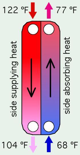
Here’s an example: Calculate the $LMTD$ for the heat exchanger shown in Figure 4-6.
To calculate the $LMTD$, assume that $(\Delta T)_1$ is for the top end of the heat exchanger. Thus, $(\Delta T)_1$ = 122-77 = 45 ºF. This means that $(\Delta T)_2$ is at bottom end of the heat exchanger. Thus, $(\Delta T)_2$ = 104-68 = 36ºF. Putting these values for $(\Delta T)_1$ and $(\Delta T)_2$ into Formula 4-3 yields:
$$ LMTD = { (\Delta T)_1 - (\Delta T)_2 \over ln \left[ (\Delta T)_1 \over (\Delta T)_2 \right]} = { 45-36 \over ln \left[ 45 \over 36 \right]} = {9 \over 0.223} = 40.3^o F $$
Now suppose that the ends of the heat exchanger representing $(\Delta T)_1$ and $(\Delta T)_2$ were reversed. Thus $(\Delta T)_1$ = 36ºF, and $(\Delta T)_2$ = 45ºF. Putting these values into Formula 4-3 yields:
$$ LMTD = { (\Delta T)_1 - (\Delta T)_2 \over ln \left[ (\Delta T)_1 \over (\Delta T)_2 \right]} = { 36-45 \over ln \left[ 36 \over 45 \right]} = {-9 \over -0.223} = 40.3^o F $$
Heat transfer theory can also be used to prove a very important concept in the application of heat exchangers. Namely that the $LMTD$ of a heat exchanger configured for counterflow will always be higher than that of the same heat exchanger configured for parallel flow and having the same entering conditions for both flow streams.
The higher the $LMTD$, the higher the rate of heat transfer. This implies that to attain the highest possible rate of heat transfer, heat exchangers should always be configured for counterflow rather than parallel flow. This concept should always be observed when planning and documenting the design of any hydronic system using heat exchangers.
DETERMINING OVERALL RATE OF HEAT TRANSFER (LMTD METHOD)
The heat transfer rate through a heat exchanger is directly proportional to the $LMTD$. It is also directly proportional to the surface area that separates the two fluids. Thus, the heat transfer rate is proportional to the multiplication of internal surface area ($A$) times the log mean temperature difference ($LMTD$). This can be expressed as the proportionality:
Formula 4-4: $$ q \ \infty \ A(LMTD) $$
Where:
$q$ = rate of heat transfer across the heat exchanger (Btu/hr)
$A$ = internal surface area separating the two fluids within the heat exchanger (ft2)
$LMTD$ = log mean temperature difference established by the current conditions (ºF)
This proportionality can be changed to a formula (e.g., an equality with an = sign, rather than a proportionality) by introducing a constant called $U$.
Formula 4-5: $$ q = UA(LMTD) $$
The constant $U$ is called the overall heat transfer coefficient of the heat exchanger. To make the units in Formula 4-5 consistent, $U$ must have units of Btu/hr/ft2/ºF. The value of $U$ is the rate of heat transfer through the heat exchanger (in Btu/hr), per square foot of internal surface area, per ºF of log mean temperature difference. The $U$-value of a heat exchanger involves knowing the convection coefficient for both fluid-to-surface interfaces, as well as the thermal conductivity of the wall separating the fluids. In some cases, additional thermal resistance effects called “fouling factors” are also included in the mathematical definition of the $U$-value.
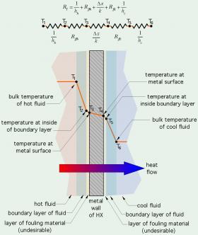
Figure 4-7 shows how the $U$-value for a heat exchanger where the two fluids are separated by a flat plate can be viewed as a sum of several thermal resistances.
The orange lines in Figure 4-7 represent relative temperature changes. The bulk temperature of the hot fluid is represented by the black dot labelled $T_1$. There is a temperature drop from $T_1$ to $T_2$ across the convective boundary layer. The extent of this temperature drop depends on the characteristics of the boundary layer. Laminar flow would result in a relatively thick boundary layer and a larger temperature drop from $T_1$ to $T_2$. Highly turbulent flow would decrease the thickness of this boundary layer and reduce the temperature drop across it.
Another temperature drop, $T_2$ to $T_3$, occurs across the resistance associated with a fouling layer. If the heat exchanger is new, or completely clean of any dirt or accumulated films, the thermal resistance of the fouling film is zero, and thus the temperature drop from $T_2$ to $T_3$ is also zero. If operating conditions allow a fouling film to develop, the thermal resistance called “fouling factor” increases, and so does the temperature drop from $T_2$ to $T_3$.
Similar temperature drops occur on the right side of the metal wall, across any fouling film and the convective boundary layer of the cool fluid.
Each of the temperature drops occurs because of a resistance to heat flow. The diagram at the top of Figure 4-7 represents these five thermal resistances, with the temperatures ($T_1$ through $T_6$) present between these resistances. The numerical value of each thermal resistance can be estimated based on several factors, such as fluid properties, flow velocity, temperature, Reynolds numbers and more. Some of these calculations can be complex and require iteration.
The overall rate of heat transfer depends on these five thermal resistances. Formula 4-5 can be expanded to show how these resistances influence the overall rate of heat transfer. That expansion is shown as Formula 4-6.
Formula 4-6:
$$ q = UA(LMTD) = { A(LMTD) \over R_T } = { A(LMTD) \over \Big[{1 \over h_h} + R_{ffh} + {\Delta x \over k} + R_{ffc} + {1 \over h_c}\Big]} $$
Where:
$q$ = rate of heat transfer across the heat exchanger (Btu/hr)
$A$ = internal surface area separating the two fluids within the heat exchanger (ft2)
$LMTD$ = log mean temperature difference established by the current conditions (ºF)
$h_h$ = convection coefficient on the hot side of the heat exchanger (Btu/hr/ft2/ºF)
$R_{ffh}$ = thermal resistance of fouling factor on hot side (ºF•hr•ft2/Btu)
$\Delta x$ = thickness of metal wall of heat exchanger (ft)
$k$ = thermal conductivity of metal wall of heat exchanger (Btu/hr/ft/ºF)
$R_{ffc}$ = thermal resistance of fouling factor on cool side (ºF•hr•ft2/Btu)
$h_c$ = convection coefficient on the cool side of the heat exchanger (Btu/hr/ft2/ºF)
From Formula 4-5 it follows that the overall heat transfer coefficient (U) can be written as Formula 4-7.
Formula 4-7:
$$ U = { 1 \over \Big[{1 \over h_h} + R_{ffh} + {\Delta x \over k} + R_{ffc} + {1 \over h_c}\Big]} $$
The values of $U$ are highly dependent on the fluids exchanging heat, the flow conditions and the characteristics of the material of which the heat exchanger is made. For water-to-water heat exchangers a guideline range for values of $U$ is 150-300 Btu/hr/ft2/ºF.
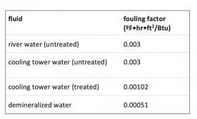
Numerical values for fouling factors are given in heat transfer reference books or on websites. The units for fouling factors are the same as for insulation R-values or other thermal resistances. In the IP units system, those units are (ºF•hr•ft2/Btu). Figure 4-8 lists some fouling factors relevant to hydronic heating and cooling applications and their associated fluids.
These values show a range of thermal resistances associated with different water conditions. Notice the fouling factor associated with demineralized water is only about 17 percent of that associated with untreated river water or untreated cooling tower water. The presence of minerals in flow streams passing through heat exchangers, especially when those fluids are at elevated temperatures, can significantly increase fouling factors and thus decrease rates of heat transfer. This again points to the importance of using high-efficiency dirt separators as well as demineralized water for optimal hydronic system performance.
The following example illustrates how Formula 4-7 can be used.
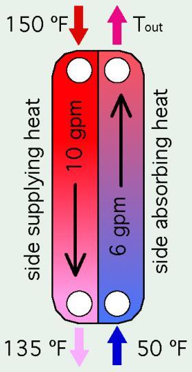
A flat plate heat exchanger is used to heat domestic water. Boiler water enters the primary side of the heat exchanger at 150ºF and flow rate of 10 gpm. Cold domestic water enters the secondary side of the heat exchanger at 50ºF and 6 gpm. The plates in the heat exchanger are 0.02 inches thick and made of 316 stainless steel having a thermal conductivity of 29 Btu/hr/ft/ºF. The heat exchanger is new, and therefore there are no fouling films on either side of the plates. The heat exchanger is configured for counterflow, as shown in Figure 4-9. Prior calculations by the designer established that the convection coefficient on the hot side of the heat exchanger is 250 Btu/hr/ft2/ºF, and on the cool side is 150 Btu/hr/ft2/ºF. Assume that the heat exchanger is operating under steady state conditions and is insulated so that external heat loss is negligible. Determine the rate of energy flow through the heat exchanger and the required internal area of the plates.
The rate of heat transfer into the heat exchanger can be determined based on the flow rate, temperature drop and physical properties of water flowing through the left side of the heat exchanger at an average temperature of (150+135)/2 = 142.5 ºF.
The density of water at 142.5ºF is 61.3 lb/ft3. The specific heat of water at this temperature is 1.00 Btu/lb/ºF.
The sensible heat rate equation (Formula 4-8) can be used to calculate the rate of heat transfer.
Formula 4-8:
$$ q = (8.01Dc) f (\Delta T) $$
Where:
$q$ = rate of heat transfer (Btu/hr)
$D$ = density of the fluid (lb/ft3)
$c$ = Specific heat of the fluid (Btu/lb/ºF)
$f$ = flow rate (gpm)
$\Delta T$ = temperature change of the fluid (ºF)
$8.01$ = constant to balance the units on each side of formula
Putting the values into Formula 4-8 yields:
$$ q = (8.01Dc) f (\Delta T) = (8.01 \times 61.3 \times 1.00) (10)(150-135) = 73,650{Btu \over hr} $$
Since the heat exchanger is operating under steady state conditions, and with insignificant external heat loss, the right side must be releasing heat at the same rate as heat is entering the left side. This allows the sensible heat rate equation to be used to determine the outlet temperature on the secondary side.
$$ T_{out} = {7350 \over (8.01 \times 62.4 \times 1.00)(6)} + 50 = 74.6^o F $$
Since both inlet and outlet temperatures are now known, the log mean temperature difference can be calculated:
$$ LMTD = { (\Delta T)_1 - (\Delta T)_2 \over ln \left[ (\Delta T)_1 \over (\Delta T)_2 \right]} = {75.4 -85 \over ln \left[ 75.4 \over 85 \right]} = {-9.6 \over -0.1198} = 80.1^o F$$
The $U$-value for the heat exchanger can also be determined based on Formula 4-7:
$$ U = { 1 \over \Big[{1 \over h_h} + R_{ffh} + {\Delta x \over k} + R_{ffc} + {1 \over h_c}\Big]} = {1 \over \Bigg[{1 \over 250 {Btu \over hr \cdot ft^2 \cdot ^o F}} + 0 + {0.00167 ft \over 29 {Btu \over hr \cdot ft^2 \cdot ^o F}} + 0 + {1 \over 100 {Btu \over hr \cdot ft^2 \cdot ^o F}} \Bigg]} = 71.1{Btu \over hr \cdot ft^2 \cdot ^o F} $$
Notice that the unit for the thickness of the heat exchanger plates was changed from 0.02 inches to 0.00167 ft. This is necessary to maintain consistent units in all terms, yielding the units of Btu/hr/ft2/ºF for the result.
Formula 4-5 can now be set up and solved for the required internal surface area of the heat exchanger.
$$ q = UA(LMTD) = 73,650 {Btu \over hr} = (71.1 {Btu \over hr \cdot ft^2 \cdot ^o F}) {\color{red}{A}}(80.1^o F)$$
$$ {\color{red}{A}} = {73,650 {Btu \over hr} \over (71.1 {Btu \over hr \cdot ft^2 \cdot ^o F}) (80.1^o F) } = 12.9 ft^2$$
The designer would now consult manufacturer’s specifications to locate candidate heat exchangers with internal surface areas of approximately 12.9 ft2.
OVERALL RATE OF HEAT TRANSFER – PIPE HEAT EXCHANGER
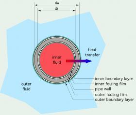
Another common “geometry” for heat exchangers involves one or more cylindrical pipes separating the two fluids exchanging heat. This is illustrated in Figure 4-10.
Formula 4-9, which is similar in mathematical form to Formula 4-6, can be used to calculate the rate of heat transfer for a pipe wall separating a hot and cool fluid.
Formula 4-9:
$$ q = {(A)(LMTD) \over \color{blue}{\Bigg[ {1 \over A_ih_i} + {R_{ffi} \over A_i} + {ln({d_o \over d_i}) \over 2 \pi kL} + {R_{ffo} \over A_o} + {1 \over A_oh_o} \Bigg] }} $$
Where:
$q$ = rate of heat transfer across the heat exchanger (Btu/hr)
$A_i$ = internal surface area of the pipe (ft2)
$A_o$ = outside surface area of the pipe (ft2)
$LMTD$ = log mean temperature difference established by the current conditions (ºF)
$h_i$ = convection coefficient on the inside of the heat exchanger (Btu/hr/ft2/ºF)
$R_{ffi}$ = thermal resistance of fouling factor on inside of the pipe (ºF•hr•ft2/Btu)
$d_0$ = outer diameter of the pipe (ft)
$d_i$ = inner diameter of the pipe (ft)
$L$ = length of the pipe (ft)
$k$ = thermal conductivity of metal wall of pipe (Btu/hr/ft/ºF)
$R_{ffo}$ = thermal resistance of fouling factor on cool side (ºF•hr•ft2/Btu)
$h_o$ = convection coefficient on the cool side of the heat exchanger (Btu/hr/ft2/ºF)
$\pi i$ = 3.141592654
$ln()$ = natural logarithm function of quantity inside ( )
Much of the effort in using a formula such as this involves gathering information and making estimates for quantities such as the two convection coefficients (h1 and h2) and the two fouling factors (Rffi and Rffo).
An important point regarding the overall heat transfer coefficient is that it depends on the convection coefficients on both sides of the heat exchanger. If one of these convection coefficients is small relative to the other, it will be the factor that limits the overall performance of the heat exchanger.
A good example of this is a coil heat exchanger inside a thermal storage tank. Based on some assumptions for typical operating conditions, the convection coefficient governing natural convection on the outer surface of the coil is only about 6% of the convection coefficient associated with forced flow inside the coil. This relatively low value will severely limit the overall heat transfer coefficient and thus require a substantially larger surface area (A) to create a given rate of heat transfer, relative to a situation where forced convection was present in both flow streams.
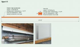
The difference between the relatively low convection coefficients associated with natural convection versus the higher values associated with forced convection can also be seen in a comparison between the length of finned-tube baseboard required for a certain heat output, versus the surface area of a coil in a wall-mounted fan-coil for equivalent heat output.
One commercially available fan-coil measuring 32 inches wide and 24 inches tall, when operating at 1.5 gpm, highspeed fan, and 110ºF average water temperature, can release approximately 6,700 Btu/hr. Standard residential finned-tube baseboard, operating at the same average water temperature and flow rate, can releases about 118 Btu/hr per foot of finned-tube length. To match the output of the fan-coil, the baseboard’s finned-tube length would need to be 6700/118 = 57 feet. Figure 4-11 shows a scaled comparison of these two heat emitters.
Even though the forced flow occurring on the inside of the copper tube in the baseboard may have a high convection coefficient, heat transfer is severely limited by the natural convection occurring between the outer surface of the finned-tube element and the room air.
DETERMINING OVERALL RATE OF HEAT TRANSFER (EFFECTIVENESS METHOD)
The method of analyzing heat exchanger performance based on LMTD is useful when the entering and leaving temperatures of both flow streams are known, or they can be calculated based on an energy balance across the heat exchanger. However, when there is insufficient information to calculate the LMTD, the solution must resort to iterative calculations. These involve making “guesstimates” for the unknown temperatures, calculating heat transfer rates based on these temperatures, finding the “error” between the calculated rates of heat transfer on the two sides of the heat exchanger, correcting the guesstimated temperatures, and repeating the procedure. This is possible but very tedious. In these situations, another method of heat exchanger analysis is usually preferred. That method is based on the concept of “effectiveness” of the heat exchanger.
The effectiveness of a heat exchanger is defined by Formula 4-10.
Formula 4-10:
$$ \mathcal{E} = {q_{actual} \over q_{max}} $$
Where:
$\mathcal{E}$ = effectiveness of the heat exchanger (decimal number between 0 and 1)
$q_{actual}$ = Actual rate of heat transfer across the heat exchanger (Btu/hr)
$q_{max}$ = Maximum possible rate of heat transfer across the heat exchanger given the operating conditions (Btu/hr)
Effectiveness is based on the concept that, with a hypothetical heat exchanger having an infinite internal area, one of the two fluid streams could undergo the maximum possible temperature change, from the inlet temperature of the cold fluid up to the inlet temperature of the hot fluid. Which fluid could undergo this temperature change depends on which has the smaller capacitance rate. The latter term, capacitance rate, is the product of specific heat times mass flow rate, expressed in units of Btu/hr/ºF.
For example: Consider a situation where one side of a heat exchanger operates with water and a flow rate of 5 gpm. The other side operates with a 50% solution of propylene glycol and a flow rate of 6 gpm. The average temperature of the fluids is 120ºF. The capacitance rate for the water side is:
$$ c_\text{water} = (5{gallon \over minute})(1{Btu \over lb \cdot^o F})({8.33lb \over gallon})({60minute \over hour})= 2499 {Btu \over hr \cdot ^o F} $$
The capacitance rate for the side operating with propylene glycol is: $$ C_\text{50%PG} = (6{gallon \over minute})(0.88{Btu \over lb \cdot^o F})({8.54lb \over gallon})({60minute \over hour})= 2750 {Btu \over hr \cdot ^o F} $$
Of these two capacitance rates, the one associated with the water side is smaller and will be designated as Cmin. The larger capacitance rate will be designated Cmax.
It’s important to note that the physical properties of the two fluids were referenced to an estimated average temperature in the heat exchanger. Also notice that the units for capacitance rate are Btu/hr/ºF. One can interpret the value of capacitance rate as the rate of heat transfer (in Btu/hr) that each fluid stream could carry into or out of the heat exchanger per degree F change in temperature of that stream.
The fluid having the lower of the two capacitance rates is one of the factors that limit the maximum possible rate of heat transfer. That maximum possible rate for a hypothetical infinitely large heat exchanger would be the lower of the two capacitance rates (e.g., Cmin), multiplied by the inlet temperature of the hot fluid minus the inlet temperature of the cold fluid. This allows the rate of heat transfer across the heat exchanger to be written as Formula 4-11.
Formula 4-11:
$$ q = \mathcal{E} \big( C_{min} \big) \big( T_{hotin} - T_{coldin} \big) $$
Where:
$q$ = actual rate of heat exchange across the heat exchanger(Btu/hr)
$\mathcal{E}$ = effectiveness of the heat exchanger (unitless valuebetween 0 and 1)
$C_{min}$ = the smaller of the two fluid capacitance rates (Btu/hr/ºF)
$T_{hotin}$ = inlet temperature of the hot fluid (ºF)
$T_{coldin}$ = inlet temperature of the cold fluid (ºF)
Although Formula 4-11 appears relatively simple, there is additional work involved to determine the value of effectiveness ($\mathcal{E}$). Two additional quantities need to be defined in order to determine the value of effectiveness ($\mathcal{E}$).
One is called the capacitance rate ratio. It’s simply the minimum fluid capacitance rate of the two fluid streams divided by the larger fluid capacitance rate, stated as Formula 4-12:
Formula 4-12:
$$ C_{ratio} = {C_{min} \over C_{max}} $$
Where:
$C_{ratio}$ = capacitance rate ratio (unitless)
$C_{min}$ = smaller of the two capacitance rates for the two flow streams involved (Btu/hr/ºF)
$C_{max}$ = larger of the two capacitance rates for the two flow streams involved (Btu/hr/ºF)
The other quantity that’s needed is called NTU, which stands for number of transfer units, and is defined as Formula 4-13.
Formula 4-13:
$$ NTU = {UA \over C_{min}} $$
Where:
$NTU$ = number of transfer units (unitless number)
$U$ = overall heat transfer coefficient for the heat exchanger (Btu/hr/ft2/ºF)
$A$ = internal area of the heat exchanger (ft2)
$C_{min}$ = smaller of the two capacitance rates of the two flow streams (Btu/hr/ºF)
One can think of the NTU as the ratio of the physical ability of a heat exchanger to transfer heat (based on its internal area and the overall heat transfer coefficient) divided by the ability of the “least able” flow stream to convey heat into or out of the heat exchanger. For example, a heat exchanger with a large internal area, and operating under favorable convection conditions, but also operating with a low capacitance rate on one side, would have high NTU. Because of its large internal area and high convection coefficients. it would be very “effective” in transferring heat to (or from) the fluid with the lower capacitance rate, possibly even approaching the performance of a hypothetical infinite heat exchanger, which would have an effectiveness of 1.0.
Once the capacitance rate ratio (Cratio) and number of transfer units (NTU) are calculated, the effectiveness for a specific type of heat exchanger can be calculated based on either formulas or graphs in heat transfer reference books.
For example, for any counterflow heat exchanger, the effectiveness can be calculated using Formula 4-14a or 4-14b. Formula 4-14a is used in the typical case where Cratio < 1. Formula 4-14b is used in the less typical but possible case where Cratio = 1 (e.g., both fluid streams have the same capacitance rate ratio.
Formula 4-14a (use when Cratio <1):
$$ \mathcal{E} = {1 - \color{red}{e^{(-NTU)(1-C_{ratio})}} \over 1-(C_{ratio})\color{red}{e^{(-NTU)(1-C_{ratio})}}} $$
Formula 4-14b (use when Cratio = 1):
$$ \mathcal{E} = {NTU \over 1+ NTU} $$
The terms shown in red in Formula 4-14a are identical and thus only have to be calculated once.
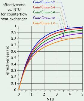
The effectiveness of a counterflow heat exchanger as a function of the number of transfer units (NTU) and the capacity rate ratio (Cmin/Cmax) can also be found using Figure 4-12.
Here’s an example: Consider a counterflow heat exchanger with an internal area of 20 ft2. It is operating with the two previously described flow streams of water at 5 gpm and 50% propylene glycol at 6 gpm. The water stream enters at 150ºF, and the propylene glycol solution enters at 60ºF. An analysis of the convection coefficients and fouling factors on both sides of the heat exchanger has been used to establish the overall heat transfer coefficient (U) as 150 Btu/hr/ft2/ºF. Determine the rate of heat transfer across the heat exchanger.
The two fluid capacitance rates have already been determined as:
$$ c_\text{water} = (5{gallon \over minute})(1{Btu \over lb \cdot^o F})({8.33lb \over gallon})({60minute \over hour})= 2499 {Btu \over hr \cdot ^o F} $$
$$ C_\text{50%PG} = (6{gallon \over minute})(0.88{Btu \over lb \cdot^o F})({8.54lb \over gallon})({60minute \over hour})= 2750 {Btu \over hr \cdot ^o F} $$
Of these two capacitance rates, the one for the water side is smaller. Thus, the capacitance rate ratio is:
$$ C_{ratio} = {C_{min} \over C_{max}} = {2499 \over 2705} = 0.924$$
The number of transfer units is:
$$NTU = {UA \over C_{min}} = {(150)20 \over 2499} = 1.2$$
These values can now be entered into Formula 4-14a:
$$ \mathcal{E} = {1 - \color{red}{e^{(-NTU)(1-C_{ratio})}} \over 1-(C_{ratio})\color{red}{e^{(-NTU)(1-C_{ratio})}}} = {1 - \color{red}{e^{(-1.2)(1-0.924)}} \over 1-(0.924)\color{red}{e^{(-1.2)(1-0.924)}}} = {0.0872 \over 0.1565} = 0.557 $$
The final step is to apply Formula 4-11:
$$ q = \mathcal{E} \big( C_{min} \big) \big( T_{hotin} - T_{coldin} \big) = 0.557(2499)(150-60) = 125,280{Btu \over hr} $$
SOFTWARE-BASED HEAT EXCHANGER SELECTION
The procedures introduced thus far — the LMTD method, and the effective ($\mathcal{E} $) method —can be used for manual calculations of heat exchanger performance. Both of these approaches demonstrate that the mathematics necessary for sizing heat exchangers can be complex. One of the more complex tasks —that was not documented in the previous examples — is estimating the values for the convection coefficients (hh and hc) in Formulas 4-7 and 4-9. Those calculations are often iterative and time consuming. As such, they don’t lend themselves to repeated “what if” scenarios when a designer is trying to select an appropriate heat exchanger.
Many manufacturers now offer software that can rapidly evaluate the necessary mathematics for sizing and selection of their heat exchangers. In some cases, this software is accessed online. In other cases, it’s necessary to download and install the software. Some suppliers also require submittal of design parameters and operate the software in-house.
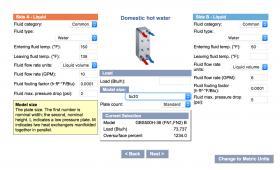
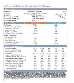
One example of online-based sizing and selection software is FlatPlateSELECT. Figures 4-13a, b and c show some examples of this software.
Some heat exchanger sizing and selection software produces a list of several specific models that can meet the requirements based on input data. They also show an “oversurface” percent, which is the percent by which the surface area in the suggested heat exchanger exceeds the minimum surface area required for the specified heat exchange rate. In some cases, the extra surface area is necessary to limit the pressure drop of one or both sides of the heat exchanger. The software provides performance data such as the overall heat transfer coefficient, flow velocity and rate of heat transfer. Physical data on the candidate heat exchangers, including volume and dimensions, are also listed. The ability of this software to evaluate several “what if” scenarios in a fraction of the time required for manual calculations makes it an essential design tool.
HEAT EXCHANGER PERFORMANCE INDICES
Two indices are commonly used to describe the actual performance, or performance target, of heat exchangers. They are:
• Approach temperature difference
• Thermal length
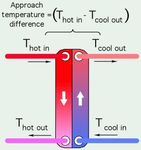
Approach temperature difference is the temperature of the fluid entering the hot side of the heat exchanger, minus the temperature of the “cooler” fluid leaving the heat exchanger. Figure 4-14 illustrates this difference.
A theoretically infinite heat exchanger would have an approach temperature difference of 0. Any real heat exchanger will have an approach temperature difference greater than zero. Some brazed plate and plate & frame heat exchangers can operate at approach temperature differences as low as approximately 2ºF, although this requires a relatively large heat transfer area, and thus a large heat exchanger.
The expense of such a large heat exchanger may not be justified based solely on a very small approach temperature difference. More typical approach temperature differences, with the heat exchanger operating at design load conditions, range from 4 to 10ºF.
Approach temperature differences are often selected based on the characteristics of the heat source. For example, the coefficient of performance (COP) of water-to-water and air-to-water heat pumps is very dependent on the load water temperature (e.g., the water temperature leaving the heat pump’s compressor). If the heat produced by a heat pump needs to pass through a heat exchanger, the approach temperature difference should be as low as practically and economically justifiable. A suggested maximum approach temperature difference for heat pump applications is 5ºF.
In another scenario, where a boiler operating at 180ºF is transferring heat to a load operating at 110ºF, the approach temperature difference is able to be much higher without significantly affecting the boiler’s efficiency. This allows use of a much smaller and less expensive heat exchanger. Keep in mind that approach temperature difference is based on a specific steady-state load. The measured approach temperature difference of a heat exchanger can vary widely when the system is operating in transient conditions.
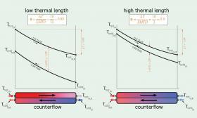
THERMAL LENGTH OF A HEAT EXCHANGER
Another concept that helps describe the expected duty of a heat exchanger is called thermal length. It’s defined by Formula 4-15.
Formula 4-15:
$$ \theta = {\Delta T \over LMTD} $$
Where:
$\theta$ = (Greek letter theta) = thermal length (unitless)
$\Delta T$ = temperature change of fluid (inlet to outlet) on one side of the heat exchanger (ºF)
$LMTD$ = log mean temperature drop at which the heat exchanger is operating (ºF)
Low values of ($\theta$) indicate heat transfer conditions that are relatively easy to accomplish. High values of ($\theta$) represent situations where there is very little difference between the temperature of the fluid providing heat and the fluid absorbing heat. The latter is a much more challenging
condition and generally requires flat plate heat exchangers with longer plates. Figure 4-15 illustrates the difference between heat transfer requirements having low and high thermal lengths ($\theta$).
Heat transfer theory limits the thermal length ($\theta$) of a single shell & tube heat exchanger to 1.0. Higher values of ($\theta$) are possible if multiple shell & tube heat exchangers are piped in series, which is uncommon. Flat plate heat exchangers can operate with thermal lengths up to approximately 10.0. This makes flat plate heat exchangers better suited to situations where the temperature differences between the fluids is minimal. The thermal length of flat plate heat exchangers can also be affected by different pressing patterns on the plate. Manufacturers can advise on optimal plate patterns based on the intended duty of the heat exchanger.
THERMAL PERFORMANCE OF WATER-TO-AIR HEAT EXCHANGERS
There are several types of heat emitters that transfer heat from a stream of water to a fan-forced stream of air. Section 2 described several of these devices, categorizing them as fan-coils or air handlers. This section will describe thermal performance concepts for these devices.
The heat output of a fan-coil or air handler is dependent on several factors. Some are fixed by the design of the product and cannot be changed. These include the:
- Surface area of the coil
- Size, spacing and thickness of the fins
- Number of tube passes through the fins
- Air-moving ability of the blower
Other performance factors depend on the system into which the fan-coil is installed and the conditions under which that system operates. These include the:
- Entering water temperature
- Water flow rate through the coil
- Entering air temperature
- Air flow rate through the coil
Most manufactures publish tables or graphs showing the heat output of a fan-coil or air handler over a range of selected operating conditions, such as entering water temperature, entering room air temperature and the flow rates of both the water and air streams. However, because heat output varies continuously with changes in temperatures or flow rates, there is no guarantee that the unit will operate at one of the conditions listed by the manufacturer.
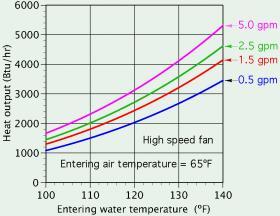
Figure 4-16 shows representative heat output from a small fan-coil unit as a function of entering water temperature and different water flow rates. The entering room air temperature is assumed constant at 65ºF, and the fan is set to its highest speed.
The manner in which the heat output of a fan-coil or air handler varies with operating conditions or coil
configuration can be summarized in four principles:
Principle #1: The heat output of a fan-coil or air handler is approximately proportional to the temperature difference between the entering air and entering water.
This principle can be expressed mathematically as:
Formula 4-16:
$$ q_2 = q_1 \Big[ {\Delta T_2 \over \Delta T_1} \Big] $$
Where:
$q_2$ = heat output at an assumed water-to-air temperature difference (Btu/hr)
$q_1$ = heat output at a known water-to-air temperature difference (Btu/hr)
$\Delta T_1$ = difference between entering water and entering air temperatures at a known operating condition (ºF)
$\Delta T_2$ = difference between entering water and entering air temperatures at the assumed operating condition (ºF)
For example, assume a fan-coil has a known output of 5,000 Btu/hr when supplied with 180ºF water and operating with room air entering at 65ºF. The designer wants to estimate the fan-coil’s output when supplied with 140ºF water, with all other conditions (e.g., room air temperature, water flow rate and air flow rate) remaining the same. Formula 4-16 yields the estimated output:
$$ q_2 = q_1 \Bigg[ {\Delta T_2 \over \Delta T_1} \Bigg] = 5,000 \Bigg[ {140 - 65 \over 180 - 65} \Bigg] = 3,261{Btu \over hr} $$
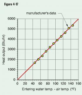
A proportional relationship between any two quantities will result in a straight line that passes through or very close to the origin when the data is plotted on a graph. Figure 4-17 shows this to be true when the heat output data for a small fan-coil is plotted against the difference between the entering water and entering air temperatures.
This relationship can also be used to estimate the heat output from a fan-coil or air handler when the entering air temperature is above or below normal comfort temperatures. For example, if a fan-coil can deliver 3,261 Btu/hr with an entering water temperature of 140°F and entering air temperature of 65°F, its output while heating a garage maintained at 50°F could be estimated using the same formula:
$$ q_2 = q_1 \Bigg[ {\Delta T_2 \over \Delta T_1} \Bigg] = 3,261 \Bigg[ {140 - 50 \over 140 - 65} \Bigg] = 3,913{Btu \over hr} $$
Although principle #1 is helpful for quick performance estimates, it should not replace the use of thermal rating data supplied by the manufacturer when it is available.
Principle #2: Increasing the fluid flow rate through the coil will marginally increase the heating capacity of a fan-coil or air handler.
Some heating professionals “instinctively” disagree with this statement. They reason that because the water moves through the coil at a faster speed, it has less time during which to release its heat. However, the time a given amount of water stays inside the fan-coil is irrelevant in a system with continuous flow. As previously discussed, the faster a fluid moves along a surface, the higher the rate of convective heat transfer. Higher rates of convective heat transfer between the water and inside surface of the tubes making up the coil result in higher heat outputs.
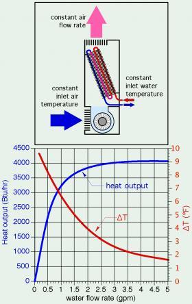
Another way of justifying this principle is to consider the average water temperature in the coil at different flow rates. As the flow rate through the coil heat exchanger increases, the temperature drop from inlet to outlet decreases. This implies that the average water temperature within the coil increases, and so does its heat output. Those who claim that a smaller temperature difference between the ingoing and outgoing fluid implies less heat is being released are overlooking the fact that the rate of heat transfer depends on both the temperature difference and flow rate. This relationship is described by Formula 4-8 discussed earlier in this section. This non-linear relationship between flow rate and heat output also applies to other heat emitters such as radiant panel circuits, panel radiators and finned-tube baseboard. It can be seen whenever heat output ratings are plotted against flow rate through the heat emitter. Figure 4-18 shows this relationship for a small fan-coil operated at a constant inlet water temperature, constant air inlet temperature and constant air-side flow rate.
The rate of heat output increases very quickly at low flow rates, but less quickly as flow through the coil increases. The fan-coil represented in Figure 4-18 released about 50 percent of its maximum heat output capacity at about 10 percent of its maximum flow rate.
The strong curvature of this relationship implies that attempting to control the heat output of a fan-coil or air handler by adjusting flow rate can be tricky. Very small valve adjustments can create large changes in heat output at low flow rates. However, the same amount of valve adjustment will create almost no change in heatoutput at higher flow rates. This is also true for other types of hydronic heat emitters.
Special types of balancing valves known as “equal percentage” valves have been developed specifically to compensate for this characteristic. An equal percentage valve allows very small increases in flow rate as the valve begins to open from a closed position. The farther the valve opens. the faster the rate at which flow-through increases. The combination of the heat output versus flow rate characteristic of the coil heat exchanger, and the flow versus stem position characteristic of an equal percentage valve, attempts to make the change in heat output approximately proportional to the percentage of stem travel in the valve.
The nonlinear relationship also implies that attempting to boost heat output from a fan-coil or air handler, and other hydronic heat emitters, by operating them at unusually high flow rates will yield very minor gains. The argument against doing this is further supported by large increases in pumping power with increasing flow rate.
Principle #3: Increasing the air flow rate across the coil heat exchanger in a fan-coil or air handler will marginally increase the heat output of the fan-coil.
This principle is also based on forced-convection heat transfer between the exterior coil surfaces and the air stream. Faster-moving air reduces boundary layer thickness and “scrubs” heat off the coil surface at a higher rate. As with water flow rates, the gain in heat output is very minor above the nominal air flow rate the unit is designed for.
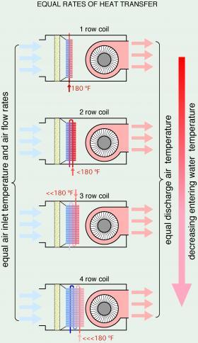
Principle #4: Fan-coils with large coil surfaces and/or multiple tube passes through the fins can yield a given rate of heat output while operating at lower entering water temperatures.
Conductive heat transfer from the tubing carrying the fluid to the aluminum fins of the coil heat exchanger increases when more tubes are used to make the coil. Convective heat transfer is proportional to the contact area between the surface and the fluid. Both of these effects allow larger liquid-to-air heat exchangers to transfer a given rate of heat at lower average water temperatures. This principle is illustrated in Figure 4-19.
This principle is very important for hydronic systems that operate with low temperature heat sources such as heat pumps. In these applications, the designer may need to use fan-coils with larger coils and/or more tube passes through the fins of the coil to drive heat from the coil at the required rate. On larger air handlers, manufacturers may offer higher-performance coils with up to eight tube rows.
Care must be taken that comfort is not compromised when operating fan-coils or air handlers at reduced water temperatures. It is critically important to introduce the air stream from such units into the space so that it mixes with room air before passing by occupants. Failure to do so will usually lead to complaints of “cool air” blowing from the fan-coils or registers, even though the room is being maintained at the desired temperature.

