POINT-OF-ENTRY PRESSURE REDUCTION
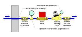
This arrangement subjects the water meter to the full pressure of the water entering the building. Some code jurisdictions may allow the water meter to be located downstream of the PRV. This reduces the pressure to which the water meter is subjected. Always verify what arrangements are allowed by the authority having jurisdiction.
The ball valves shown in Figure 3-1 allow water service to the house to be turned off. Their placement also allows the water meter or the pressure reducing valve to be isolated if either requires service. An optional upstream pressure gauge is shown (where allowed by code).
INDEPENDENT HOT & COLD WATER PRESSURE REDUCTION
Caleffi pressure reducing valves can be used on both hot and cold water plumbing. The maximum hot water temperature for Caleffi pressure reducing valves is 180ºF.
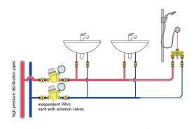
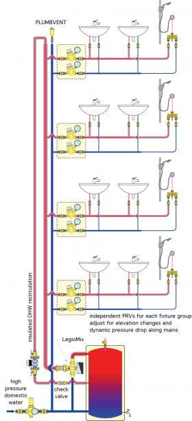
Figure 3-2 shows an example of two Caleffi 535H valves that control pressure to a group of plumbing fixtures supplied by building distribution piping operating at high pressure.
Using two independent valves allows for pressure variations in the hot and cold water distribution system. Such variations are common based on different pipe lengths, fittings count or pressure drops through heat source equipment in the hot water distribution system.
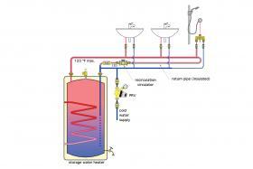
When the building is equipped with a recirculating domestic hot water system, pressure reducing valves should not be installed in any of the recirculating piping. They can, however, be installed on “dead-end” runs that tap into the recirculating circuit. In small systems, where pressure variation between the hot and cold water distribution piping is minimal, it is generally acceptable to install a single PRV on the cold water piping leading to the system, as shown in Figure 3-3.
See idronics #22 for a detailed discussion of recirculating domestic hot water systems:
idronics #22
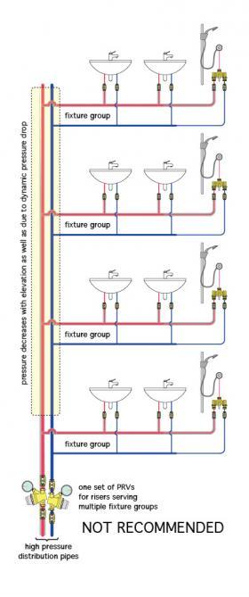
When several fixture groups are supplied by a set of hot and cold domestic water pipes, one option would be to install a PRV on each of the riser pipes and set them for the desired downstream pressure. This concept is shown in Figure 3-4.
However, this approach has several drawbacks:
- It does not prevent pressure variations due to the different elevations of the fixture groups.
- It does not compensate for dynamic pressure drop along the risers,which increases during typical periods of high demand when many of the fixture groups are operating.
- This undesirable effect would also be present if the fixture groups were located at the same elevation in the building
- Using a single pair of PRVs on the risers does not allow domestic hot water recirculation. Given these shortfalls, this is not a recommended approach.
A better option is to locate a pair of PRVs upstream of each fixture group, as shown in Figure 3-5.
This arrangement eliminates all of the previously stated issues associated with a single pair of PRVs on each riser.
It allows for pressure compensation based on elevation, dynamic pressure drop along the risers, and hot water recirculation.
OUTDOOR MOUNTING
It is possible — although not preferred — to mount a pressure reducing valve outside of the building it serves. Such mounting is more common for buildings located in mild climates with slab-on-grade foundations. However, this should never be done in any location where outdoor temperature could drop to at or below freezing.
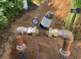
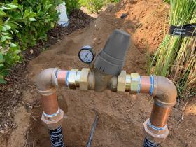
Figure 3-6a shows an example of a pressure reducing valve that is mounted outside a house between two riser pipes.
If the valve is mounted outside, its polymer components are exposed to ultraviolet radiation from the sun. Caleffi offers a UV shield that can be installed over the polymer portion of the 535H PresCal valve, as shown in Figure 3-6b. This shield is only intended to protect the valve from UV radiation. It does not protect the valve from tampering, freezing or physical damage. The external surfaces of the Caleffi 536HP pressure reducing valve are brass, and as such do not require UV shielding.
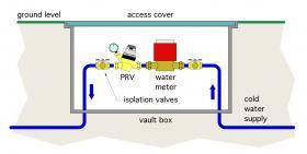
If the valve is to be mounted outside, the preferred method is to house it and its associated isolation valves in a buried “vault” box, as illustrated in Figure 3-7. This mounting can prevent unauthorized access, protect the valve from UV radiation and physical damage, and provide some measure of protection against short-duration sub-freezing air temperatures.
MAINTAINING PRV PERFORMANCE
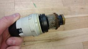
Caleffi pressure reducing valves are designed for long life and minimal maintenance. They include a stainless steel inlet screen designed to capture dirt carried into the valve by upstream flow.
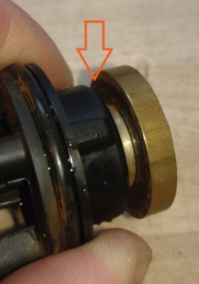
Heavily encrusted inlet screens will reduce the flow capacity and the pressure regulation accuracy of the valve. Very fine dirt particles may be able to pass through the screen and collect on the valve’s precision-machined seat, as shown by the arrow in Figure 3-9.
Dirt accumulation on the valve’s disc or seat can prevent pressure-tight closing, causing the pressure on the downstream side to creep above the valve’s set pressure during periods of no water demand.
Dirt accumulation on the inlet screen or valve seat is easily removed. Start by closing the isolation ball valves on each side of the PRV. Then unscrew the pressure regulating cartridge from the valve’s base. This exposes the screen and disc assembly.
Most debris can be removed from the screen and seat area using an old toothbrush along with a detergent. After cleaning both the screen and disc/seat area, the cartridge can be reinstalled on the base and the valve returned to service.
OTHER TROUBLESHOOTING SCENARIOS
Likely cause: If a PRV is oversized for the flow rates required, it can “hunt” for the proper modulation. This can occur when the flow velocity is under 1 foot per second in an oversized valve. Under such conditions, the valve can’t find equilibrium, so the seat oscillates open and closed rapidly, causing the chatter sound.
Corrective action: Select a PRV based on its rated flow rate range. Keep in mind that a properly sized PRV may not always match the pipe size at the location where it is installed in the system. As an example, a 1” PRV might be the proper selection for the maximum flow demand, even if the water meter and piping to the rest of the system is engineered to be 1-½”. In commercial settings, consider installing a high/low PRV assembly (two PRVs in parallel, as shown in Figures 2-20 and 2-21), which can modulate down to the lowest flow requirement while also meeting the highest flow demand.
Likely cause: The PRV may be undersized for the maximum flow rate required. For example, a building expansion may result in more fixtures connected to the same water supply main. The maximum flow rates may now be higher than the flow for which the PRV was sized.
Corrective action: The PRV may need to be replaced with a larger PRV. Always consult the product literature for proper sizing based on maximum flow rates and a velocity range of 3-6 feet per second.
Likely cause: Debris in the system can build up and slowly clog plumbing components. This can occur when the system is commissioned due to debris in piping that migrates into the PRV. Clogging can also occur after service work on municipal water mains or following a large water drawdown in a well. Debris from corroded piping can also get carried into the screen of the PRV.
Corrective action: If all of the fixtures in the system are experiencing reduced flow, a good place to start is as close to the water meter as possible. Turn off the main water supply isolation valve. Next, remove the cartridge assembly from the PRV and clean it using an old toothbrush and detergent.
Be sure to clean the disc and valve seat, as well as the screen. Reinstall the clean cartridge and open the water main valve. If the system flow returns to normal, no further action is needed. If the flow rate is still diminished, check for debris in any downstream components containing screens or filters.
If the clogging persists, consider adding a wye strainer, rated for domestic water service, upstream of the PRV to reduce the need to disassemble the PRV for cleaning.
SUMMARY
The proper delivery of domestic hot and cold water requires attention to pressure variations from the water source. Excessively high pressure can lead to several problems, both for the components of the plumbing system, as well as the building occupants using fixtures and appliances.
Fortunately, automatic pressure regulation is simple to achieve using modern pressure reducing valves.
When properly sized, these valves continuously adapt to potentially wide fluctuations in supply water pressure, enabling consistent and enjoyable use of fixtures, as well as extending the life of plumbing system components.

