Previous sections have described commonly encountered design or installation errors that compromise the performance of hydronic systems. This section presents examples of systems that embody several of those errors, and it shows at least one modified design that eliminates them. Many of the errors shown have been found, often repeatedly, in real installations.
1. WHAT’S WRONG: Incorrect attempts at creating primary/secondary piping.
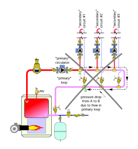
The system shown in Figure 5-1a is an undefined piping layout. It attempts to combine the concept of a primary loop with the concept of supply and return headers. The designer’s objective was to provide the same supply water temperature to each of the three load circuits. Thus, the tees that supply each load circuit are located upstream of the tees that route water returning from the load circuits back to into the “primary loop.” This piping arrangement is the likely result of someone beginning to design a system around a primary loop, but in the process, reverting to the concept of “headers” when connecting the load circuits to that primary loop. The result is neither a primary/secondary system, nor any other acceptable piping topology.
The problem with this piping arrangement is the pressure differential created by head loss along the “primary loop.” This pressure differential can induce flow through one or more of the load circuits when those circuits are not supposed to be delivering heat.
For example: Consider the pressure drop from point A to point B along the “primary loop” shown in Figure 5-1a. This pressure drop is due to head loss created by flow moving along the “primary loop.” Once this pressure drop exceeds the forward opening threshold of the spring-loaded check valves in a given circulator, flow will be pushed through that circulator and its associated circuit. This will deliver heat to the space served by that circuit when there is no call for such heat.
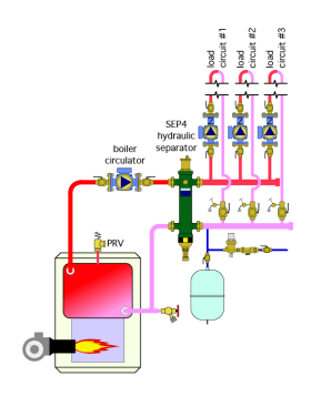
One solution: The system shown in Figure 5-1b solves the problems described previously, while providing equal supply water temperature to each load circuit. This system uses a Caleffi SEP4 hydraulic separator to decouple the pressure dynamics of the boiler circulator from that of the load circulators. The SEP4™ also provides air, dirt and magnetic particle separation for the system. The short and generously sized headers in combination with the SEP4™ also decouple the pressure dynamics of the load circulators from each other. Each load circuit receives water at the same supply temperature.
2. WHAT’S WRONG: A temperature-responsive boiler bypass circulator is installed with the intent of preventing sustained flue gas condensation, but condensation still occurs.
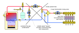
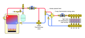
The system shown in Figure 5-2a uses a temperature-responsive “bypass” circulator that is supposed to boost boiler inlet temperature to a level where sustained flue gas condensation will not occur. A 3-way thermostatic mixing valve is used to control supply water temperature to the low-temperature/high-thermal mass load. The original concept for this design is that the bypass circulator would increase speed when it detects that the boiler inlet temperature is below its setpoint (e.g., low enough to allow sustained flue gas condensation).
However, regardless of the flow rate created by the bypass circulator, this arrangement cannot increase the rate of heat generation by the boiler to match that temporarily created by the high thermal mass distribution system. To ensure anti-condensation protection, the mixing system must have the ability, when necessary, to completely uncouple the heat production of the boiler from the heat dissipation of the load.
One modification that solves the sustained flue gas condensation issue is to install a Caleffi ThermoProtec™ valve, as shown in Figure 5-2b. The ThermoProtec™ valve contains a thermostatic element to sense the boiler inlet temperature whenever the boiler circulator is operating, and when necessary, restrict the amount of cool fluid returning from the load so that the boiler inlet temperature remains above 130ºF.
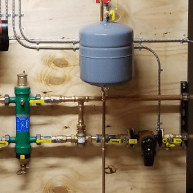
Figure 5-2c shows an installation where a ThermoProtec valve is used to prevent sustained flue gas condensation in a cast iron boiler supplying a low-temperature distribution system.
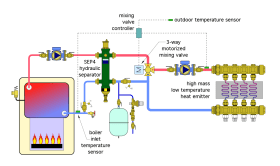
Another viable option is to use a motorized 3-way mixing valve operated by a controller that senses boiler inlet water temperature as well as the supply water temperature to the load, as shown in Figure 5-2d. This design eliminates the need to use two mixing valves, one for supply temperature control and the other for boiler protection. It replaces the central air separator and closely spaced tees with a SEP4™ hydraulic separator to provide hydraulic separation between the boiler circulator and load circulator. The SEP4™ also provides air, dirt and magnetic particle separation.
3. WHAT’S WRONG: Lack of hydraulic separation, heat migration into inactive zones and high electrical energy use.
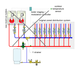
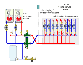
An installer is asked to retrofit two high-efficiency mod/con boilers to an existing multi-zone distribution system. Each of the new boilers was shipped with a dedicated circulator. The installer included a Y-strainer to capture possible dirt in the existing portion of the system before it could enter the boilers. Figure 5-3a shows the resulting piping. The main problem with this layout is that the boiler circulators are in series with the load circulators.
Either boiler circulator, when operating, sets up a pressure differential between the supply and return headers, which will likely cause some flow in all the zone circuits that are supposed to be off (assuming that the pressure differential exceeds the forward opening resistance of the flo-control valves, which is typically about 0.5 psi). Other deficiencies include lack of isolation valves to service the Y-strainer, or to isolate either boiler if necessary.
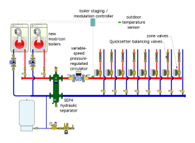
Figure 5-3b shows a revised design that provides hydraulic separation between the boiler circulators and the load circulators. The Caleffi SEP4™ provides hydraulic separation as well as high-efficiency air, dirt and magnetic particle separation. The latter function is especially important in older systems that often contain more ferrous metal and older seals, and thus, have a higher likelihood of containing iron oxides. The Y-strainer and central air separator are no longer necessary.
If this system were being designed without the need to include the existing zone circulators, a single variable-speed pressure-regulated circulator could be used in combination with a zone valve on each load circuit. This configuration would use significantly less electrical energy, while still providing stable and independent control of each load circuit. Figure 5-3c shows this configuration, which might also be justified as a retrofit strategy based on electrical cost savings.
4. WHAT’S WRONG: Short cycling of heat sources resulting in wasted energy.
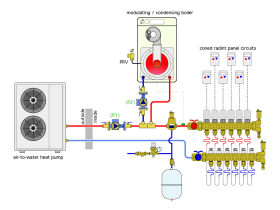
Figure 5-4a shows one attempt at combining a monobloc air-to-water heat pump with an auxiliary mod/con boiler. The load is a highly zoned radiant panel heating system. The thought behind this design was to let the heat pump supply warm fluid to the zone loads whenever possible, but also to use a temperature sensor input on the boiler to monitor the supply water temperature to the manifold station, and fire the boiler when necessary to boost that supply temperature. If the outdoor temperature was too cold for the heat pump to operate, the boiler would become the sole heat source.
Problems with this design include the need to keep the heat pump circulator (P1) operating whenever there is a call for heat from any zone. This would be true even if the heat pump was down for service. This configuration could potentially dissipate large amounts of heat outside the building during times when the boiler is the sole heat source. If the heat pump had to be removed for repair, temporary piping to complete the piping loop would be necessary.
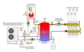
There is also going to be short cycling of both heat sources since neither can modulate their heat output low enough to match the demand of a single operating load circuit. Figure 5-4b shows a modified design that avoids these issues. Both heat sources are piped in parallel, and each can operate independently. Both heat sources connect to a buffer tank that moderates between the rate of heat production and heat dissipation by the highly zoned distribution system. A variable-speed pressure-regulated circulator automatically adjusts its speed in response to the number of active zones.
The entire system operates with a 30% solution of propylene glycol antifreeze, which is necessary to protect the heat pump from freezing. Spring-loaded check valves prevent reverse thermosiphoning from the buffer tank, as well as flow reversal when only one heat source is operating. A 2-stage controller maintains the temperature of the buffer tank based on outdoor reset control, which reduces water temperature under part load conditions and improves the seasonal COP of the heat pump. A 2-port purging valve allows the antifreeze solution to be pumped into the system through one port, while air exits through the other port. Flexible reinforced hoses are used to reduce vibration transmission from the heat pump to the rigid piping.
5. WHAT’S WRONG: Unstable operation when high-mass and low-mass heat emitters are combined, a damaged heat source, flow reversal and noise from certain radiator valves.
This system is based on a design for a modest super-insulated home in a cold Northern climate. The home’s design load is only 18,000 Btu/hr. The owners are planning to install a 12 KW solar photovoltaic electrical system, with the hopes of operating the house on a “net zero” basis. The local utility offers net metering, allowing surplus electrical power to be sent to the grid at full retail rate. Some of that “banked” electrical energy can be used during nighttime or on low solar gain days.
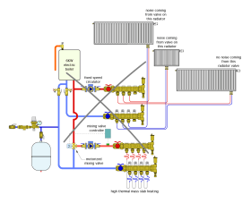
The designer has selected a 6 KW (20,500 Btu/hr) electric boiler for the heat source. That boiler will supply floor heating in the basement slab, and three panel radiators on the main floor. The system was installed as shown in Figure 5-5a.
The owners report that, although the system is generally comfortable, they’ve noticed the main living room areas served by the panel radiators get cool and remain that way for two or three hours whenever they turn up the basement thermostat. Other issues reported by the owners include having to replace some burned-out heating elements in the boiler, air noise in the system, occasional flow noise when only one panel radiator is operating and heat migrating into the floor heating portion of the system when the panel radiators are operating.
There are several issues with this system. They include:
• Electric boilers require a minimum flow rate whenever they operate to prevent their elements from overheating. If only one panel radiator is operating, it’s likely that this minimum flow rate through the boiler would not be met, and hence the underlying reason for the burned-out elements.
• The use of a fixed-speed pump, in combination with the thermostatic valves on the radiators, requires some means of differential pressure control. Without this control, flow noise can occur at the thermostatic radiator valves when only one of the radiators is allowing flow, and thus, the fixed-speed circulator is operating at high differential pressure.
• This design places the panel radiator subsystem and the floor heating subsystem in parallel. Without check valveson the return side of both subsystems, flow reversal is possible whenever one subsystem is on and the other is off. This is likely the underlying reason for heat migration into an inactive subsystem when the other subsystem is operating.
• The drop in heat output from the radiators when the basement floor-heating thermostat is turned up is due to the high-thermal mass floor slab temporarily absorbing heat at a rate higher than the output of the boiler. This transient condition would eventually diminish but would reoccur each time the thermostat controlling the floor slab portion of the system is turned up, especially following a deep setback condition.
• The noise coming from two of the thermostatic radiator valves is due to a reversal of the supply and return piping connecting at the bottom of the radiator. This reversal causes flow to move backward through the radiator’s valve, which can result in cavitation or “thumping” sounds when the valve plug is close to its seat. Most panel radiators have specific requirements on where the supply and return piping connect. The most common configuration has the supply on the left, and the return on the right, as viewed from the front of the radiator. Technicians should always verify that flow passes through radiator valves in the correct direction. Small details matter...
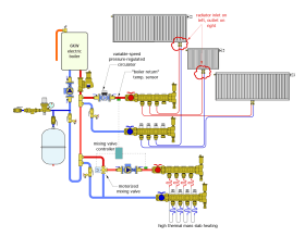
Figure 5-5b shows a modified design for the system.
The modified design uses a boiler loop with a dedicated circulator to ensure the necessary flow through the boiler whenever it operates. The loop is equipped with a DISCAL® air separator, makeup water assembly and purging valve. Both subsystems are connected to the boiler loop using closely spaced tees. These tees provide hydraulic separation between the circulators in the subsystems and the boiler circulator. The panel radiator subsystem is connected closest to the boiler to receive the higher available water temperature. A variable-speed pressure-regulated circulator provides flow and differential pressure control as the thermostatic valves on the radiators open and close.
A key feature in the modified system is to use the “boiler return” temperature sensor to detect the water temperature supplied to the manifold station serving the panel radiators. The mixing valve controller monitors the temperature of this “boiler return” sensor whenever the floor-heating subsystem is operating. If the supply temperature to the radiators drops below the minimum “boiler return” setting of the controller, the 3-way mixing valve begins to reduce the hot water portion of the mixed stream — as necessary — to maintain a minimum supply temperature to the radiators, and prevent a drop in heat output from the radiators when the floor slab is undergoing transient warm-up. The boiler would be operating at full output under such conditions, delivering heat to the building as fast as possible, but “favoring” heat output from the radiators as the slab warms to its nominal operating temperature.
All three radiators now have the supply pipe connecting on the left and the return pipe on the right. This provides the correct flow direction through the radiator valve, preventing cavitation or other sounds.
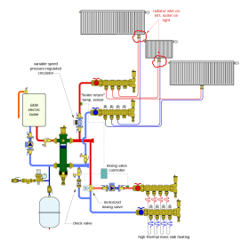
Figure 5-5c shows another possibility.
Figure 5-5c shows another possibility. This design uses a SEP4™ hydraulic separator to eliminate the need for the closely spaced tees and air separator. It also likely reduces the piping and fitting count for the boiler loop, and provides dirt and magnetic particle separation, which was not provided in the previous designs. The short and generously sized headers on the load side of the separator ensure good hydraulic separation between the variable-speed pressure- regulated circulator supplying the panel radiators, and the fixed-speed circulator supplying the slab heating circuits.
The mixing valve controller still monitors the supply water temperature to the panel radiators using its “boiler return” sensor, and reduces hot water flow into the mixing valve, when necessary, to ensure adequate supply water temperature to the panel radiators.

