Just as physicians can quickly “zero in” on the likely cause of a health issue by observing “classic” symptoms, technicians can quickly identify what’s causing a problem in a hydronic system that exhibits “classic” symptoms. This section presents many of these commonly encountered symptoms, provides one or more possible causes, suggests things to check and lists potential corrective actions.
Technicians need to remember that a given symptom could have multiple underlying causes. For example, a noisy zone valve could be caused by the use of a “high head” fixed-speed circulator, improperly set differential pressure bypass valve or by debris jammed inside the valve. Likewise, an underlying problem could manifest itself through several different symptoms. For example, air in a system could present as noise in the piping, insufficient flow rate, insufficient heat output at a heat emitter or corrosion. Thus, the information presented in this section should be considered as “starting points” when investigating a problem. Troubleshooting experience, gained over time and multiple systems, will expedite the process of identifying underlying causes for abnormal performance, and will help in selecting the best course of action for correcting the problem(s).
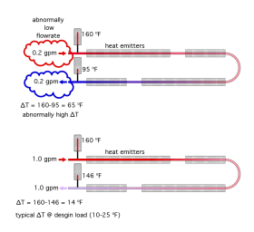
1. SYMPTOM: Large temperature drop between the supply and return sides of a hydronic heating circuit.
Possible cause(s): Most hydronic heating circuits that operate with a temperature drop of more than 25°F when the heat source is delivering water at design load temperature are suffering from low flow rate. The possible exception being panel radiators or heating coils in air handlers that are sometimes intended to operate at design load temperature drops of 25°F to 30°F.
Figure 4-1 illustrates the concept of insufficient flow rate causing a high temperature drop.
Things to check:
• Does the circulator have a pump curve sufficient for the intended flow rate in the circuit?
• Is the speed setting of the circulator too low?
• Does the temperature drop across the circuit change when the speed setting of the circulator is changed?
• Is the circulator wired for the correct voltage (120 or 240 VAC)?
• Is there evidence of air in the fluid (gurgling or swishing sounds)?
• Is there evidence of vapor cavitation (crackling sounds coming from the circulator)?
• Does the piping circuit have significantly more components or fittings than necessary or originally planned, causing higher head loss?
• Are there any partially closed or improperly selected valves that are restricting flow in the circuit?
• Are there any y-strainers, check valves, filters or other devices in the circuit that could be clogged?
• Is the pipe size too small for the intended flow rate?
Things to check (continued):
• Was the circuit designed assuming water as the fluid, but is now operating with a higher percentage of glycol-based antifreeze?
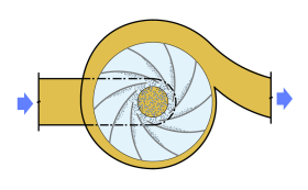
• Are there any abnormal sounds coming from the circulator that could indicate debris stuck in the volute or impeller?
• Are there any large dents or deformations in any tubing within the circuit?
• Was the original cast iron boiler replaced with a high-flow resistance mod/con boiler without some type of hydraulic separation between the new boiler and remainder of system?
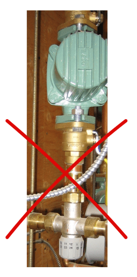
• Is there a thermostatic mixing valve with a low Cv in the circuit that has been selected based on pipe size?
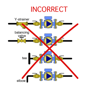
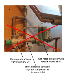
If so, it could create a significant flow bottleneck, especially problematic when installed near the circulator inlet. (See Figure 4-2).
Potential corrective action(s): Because there are many possible causes for this condition, the corrective action is to verify proper functioning or sizing for each of the “things to check.” Some calculations may be necessary to determine if a larger circulator is needed.
See idronics #16 for detailed information on sizing piping and circulators:
2. SYMPTOM: Flow is present in portions of system that are supposed to be off.
Possible cause(s):
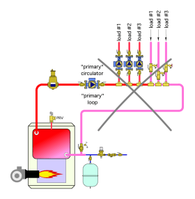
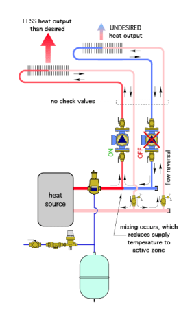
• An undefined piping layout that “morphs” the concept of a primary loop with the concept of supply and return headers. Figure 4-3a shows one example.
• Lack of a check valve in each circuit that has a zone circulator (see Figure 4-3b).
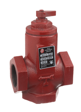
• Stuck check valve or older-style “flo-control” valve in circuits exhibiting flow when the circulator is off. Figure 4-3c shows an example of an older-style “flo-control” valve.
• The plug in an older-style “flo-control” valve has been left in the manually open position.
Possible causes (continued):
• Using a swing-check in an attempt to prevent forward thermosiphon flow.
• A zone valve that fails to close when the zone thermostat is satisfied. Potential corrective Action(s):
• Modify any undefined piping system into a proven piping configuration (see idronics #19).
• Verify that all zone circuits using zone circulators have a spring-loaded check valve, or a flo-control valve, and that those valves are not jammed, clogged, left in a manually open state or otherwise compromised.
• Never use swing-check valves in an attempt to stop forward thermosiphoning. They do not have sufficient forward opening resistance.
• Verify that the actuator on the zone valve in the problem circuit fully closes when the thermostat is not calling for heat. If the actuator moves through its full range of travel and the problem persists, there may be debris stuck in the valve, preventing it from closing. Depending on the valve, it may be possible to flush the debris using pressurized water, or isolate and remove the valve body to check its internal operation.
See idronics #19 for proven hydronic distribution systems:
3. SYMPTOM: Inadequate flow in some branches of a distribution system.
Possible cause(s):
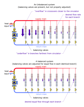
The flow rate in any branch of a multi-branch system depends on the flow resistance of that branch relative to that of the other branches. The higher the flow resistance of a given branch, the lower its flow rate relative to branches with less flow resistance. Figure 4-4 compares an unbalanced system with a balanced system. The assumption for the balanced system is that the same flow rate is desired through each branch.
Adjusting the system to achieve the desired flow rate in each branch is called balancing, and it requires a properly adjusted balancing valve in each branch. The lack of balancing valves, or the improper setting of balancing valves (if present), is often the cause of inadequate flow in some branches.
Things to check:
• Are balancing valves present in each parallel branch?
• If balance valves are present, have they been adjusted to achieve the desired flow rate in each branch?
• Aside from the balancing valves, are there any devices in the branch experiencing inadequate flow that could be causing high flow resistance (plugged Y strainers, other valves, high fittings count, high flow resistance heat emitters, etc.)?
Potential corrective action(s):
After ruling out devices that could cause high flow resistance in the problem branch, and assuming balancing valves are present, follow a standard balancing procedure to set the balancing valves. If adequate flow in all branches cannot be achieved, it’s likely that a larger circulator is needed.
See idronics #8 for a detailed discussion on hydronic system balancing:
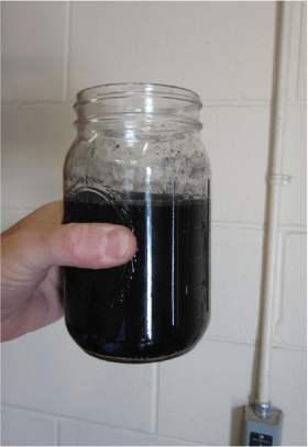
4. SYMPTOM: Dark-colored water/fluid in the system.
Possible cause(s):
Water in a closed-loop hydronic system typically takes on a light gray hue and a slight metallic odor during the first few weeks of operation. This is generally normal. Dark-colored water (or a mixture of water and antifreeze) usually indicates that oxygen is entering the system and has reacted with ferrous metals to form oxides. It can also indicate thermal degradation of the antifreeze, especially in systems that have operated at elevated temperatures.
Things to check:
• If the system contains antifreeze, obtain test strips from the antifreeze manufacturer, or a test meter, as shown in Figure 4-5, and test the pH of the fluid. A normal pH should be between 7.0 or 8.0. If the pH is lower than 7.0, the antifreeze may have become acidic and should be replaced. Check with the boiler manufacturer for the acceptable range of pH required on their equipment.
• Does the system experience frequent infusions of fresh water due to a relief valve that cycles open repeatedly?
• Does the system contain non-barrier polymer or rubber tubing?
• Has anyone been intentionally draining and refilling the system?
Potential corrective action(s):
• Antifreeze that has become acidic should be disposed of properly. The system piping should be flushed and internally cleaned with a hydronic system detergent. If the system is to be refilled with antifreeze, the water used to make the antifreeze solution should be demineralized.
• If the system contains non-barrier tubing, and there is no practical way to replace that tubing with barrier- type tubing, the discolored fluid should be drained, the system internally cleaned with a hydronic detergent, and refilled with demineralized water. A chemical treatment manufacturer should be consulted to determine an oxygen-scavenging chemical that can be periodically added to the system. Makeup water should be minimized, and the system should be operated at the lowest water temperature that can deliver adequate heating. Adding a Caleffi DIRTMAG® PRO separator to the system will also help collect magnetite at a location where it can be periodically flushed from the system.
See idronics #18 for more details on maintaining water quality in hydronic systems:
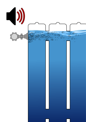
5. SYMPTOM: Air noise inside the system.
Possible cause(s):
• Lack of forced-water purging during system commissioning or refilling following service.
• Gaseous cavitation within the circulator (see Figure 4-6a).
• Lack of a central microbubble air separator.
• An expansion tank improperly located relative to the circulator.
• Air trapped at one or more high points in the piping circuit (see Figure 4-6b).
• A drop in system pressure leading to sub-atmospheric pressure at the location of the air vents.
• Water draining from the piping located higher than a non-pressurized heat source when the circulator is off, and refilling piping when the circulator turns on.
Things to check:
• Has the system been purged using a forced-water stream since it was installed or last drained?
• Are there any manually operated air vents at high points in the circuit that can be opened to release trapped air?
• What is the static pressure in the system? A minimum pressure of 12 psi in the basement is suggested for closed- loop hydronic systems in low-rise (three-story or less) buildings.
• Is there a cap on the top of the central air separator vent that is screwed down tight?
• Are there any air vents, valves or other devices that could allow air into the system when the pressure inside the piping is sub-atmospheric? This is most common when non-pressurized heat sources, such as outdoor wood furnaces, supply piping that is routed several feet above the water level in the heat source?
• Is the makeup water assembly turned off, which could allow the system pressure to drop over time?
Potential corrective action(s):
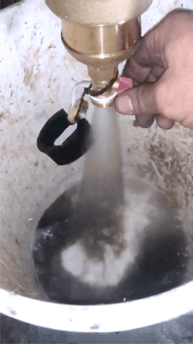
• Set up and perform a forced-water purging of the system. Purge each branch or zone of the system separately. Be sure there are no air bubbles in the purging stream exiting the system.
• Consider adding purging valves in portions of the system that have chronic air problems.
• If the system doesn’t have one, install a microbubble air eliminator, such as a Caleffi DISCAL. Be sure the cap on the vent of the air separator is not screwed down tight.
• Verify that static pressure in a closed-loop system installed in a low-rise building is at least 12 psi.
• Relocate the expansion tank connection near the inlet of the circulator.
See idronics #16 & #18 for information on the proper placement of expansion tanks:
6. SYMPTOM: Frequent opening of the system’s pressure relief valve.
Possible cause(s):
• A defective pressure-relief valve.
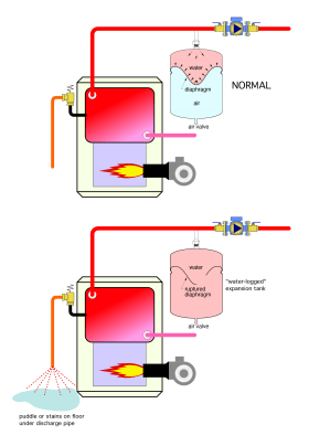
• A ruptured diaphragm in the expansion tank, causing it to fill with water (see Figure 4-7a).
• An undersized expansion tank.
• A water-logged standard (non-diaphragm) compression tank.
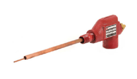
• A failed or missing air level control device, typically required when a standard (non-diaphragm) type expansion tank is used. An example of such a device is shown in Figure 4-7b.
• Debris in the pressure-reducing valve supplying makeup water to the system.
• Unnecessarily high static pressure in the system.
• High system static pressure combined with a high head circulator.
• Leakage from a relief valve due to debris on the valve seat.
Things to check:
• Is the size of the expansion tank correctly matched to the system volume and temperature range?
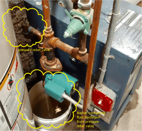
• Is there a bucket placed under the discharge pipe from the pressure- relief valve that either contains water or shows signs that it did contain water (see Figure 4-7c)? This is an indication of leakage or discharge from the valve.
• Is there any evidence of water (such as a mineral trail) on the floor under the relief valve discharge pipe?
Things to check (continued):
• Is the air pressure in the diaphragm-type expansion tank, as measured with an accurately calibrated gauge, properly adjusted to match the cold- water static pressure in the system?
• Is there water coming out of the Schrader valve on a diaphragm- type expansion tank when the stem of the valve is pressed in? If so, the diaphragm in the tank has failed and the tank needs to be replaced.
• What is the water level in the sight glass on a standard (non-diaphragm) expansion tank?
• Is an air level control device missing at the bottom of a standard (non- diaphragm) type expansion tank?
• What is the static pressure in the system?
Potential corrective action(s):
• Replace any diaphragm-type expansion tank if the diaphragm has failed.
• Verify that the expansion tank is properly sized and pressurized for the system.
• Allow the makeup water system to refill a standard expansion tank and verify the proper water level in the tank.
• Reduce the pressure setting of the pressure-reducing valve.
• Isolate and disassemble the pressure-reducing valve supplying water to the system, clean the screen and valve seat, and reassemble.
• Install or replace the air level control device on systems with standard expansion tanks.
See idronics #12 for information on sizing and pressurizing diaphragm-type expansion tanks:
7. SYMPTOM: Noise coming from the zone valves.
Possible cause(s):
• The flow rate through the valve is excessive due to high differential pressure across the valve.
• There is no means of differential pressure control in the system.
• A circulator with a “steep” pump curve is creating flow through the zone valves.
• Cavitation is occurring within the zone valve.
• Debris is lodged within the zone valve.
• The paddle or disc in the valve only opens through a portion of its normal range.
• Incorrect flow direction though the valve.
Things to check:
• What (if any) method of differential pressure control is used in the system?
• If a differential pressure bypass valve is present, what ∆P is it set for?
• If a variable-speed circulator is used, what operating mode is it set for?
• Is a “high head” fixed-speed circulator being used to create flow through the zone valves?
• Is the combination of high water temperature and low static pressure in the system sufficient to cause cavitation (vapor flashing) within the zone valve?
• Is flow passing through the valve in the correct direction?
Potential corrective action(s):
• Add some means of differential pressure control to the system. This could be a properly set differential pressure bypass valve, or a variable-speed circulator operating in constant ∆P or proportional ∆P mode, and with a setting reasonably matched to the differential pressure requirements of the system at design load conditions.
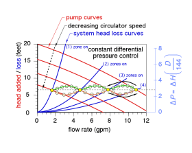
Figure 4-8a shows an example of constant differential pressure control for a system with four zone valves.
Each blue system head loss curve represents the head loss of the piping circuit as a function of flow rate. The curve gets progressively steeper as the number of active zone valves decreases. The variable-speed circulator, operating in constant differential pressure control mode, automatically adjusts its motor speed so that its pump curve intersects the system head loss curve at the differential pressure to which the circulator has been set. This is an ideal way to control differential pressure in any hydronic system using valve-based zoning.
See idronics #7 for more detailed information on zoning hydronic systems.
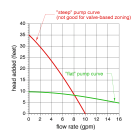
• If a fixed-speed circulator is used to create flow through the system’s zone valves, it should have a relatively “flat” pump curve. If a high head circulator with a “steep” pump curve is present, it should be replaced. Figure 4-8b shows a comparison between flat versus steep pump curves.
• If flow rate is too high for the current valve, consider a valve with a higher Cv rating.
• If cavitation is occurring within the valve, consider reducing water temperature and increasing system static pressure to prevent the water passing through the valve from reaching its vapor pressure.
• If none of the above actions correct the problem, disassemble the valve to check for debris, broken internal components or anything that limits the travel range of the paddle or disc in the valve. If damage is found, replace the valve body.
8. SYMPTOM: “Ticking” sounds from the piping.
Things to check:
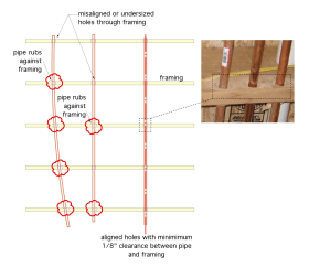
• Are the holes through the framing for the piping misaligned, causing the pipes to rub against the framing in some locations (see Figure 4-9a)?
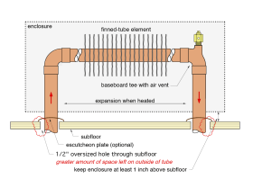
• Do locations where the piping passes through the framing or subfloor allow space between the outer surface of pipe and the holes through the framing (see Figure 4-9b)?
• Are some pipes rigidly clamped to wooden surfaces?
• Are there long lengths of straight pipe without expansion/ contraction detailing?
• Does the system frequently undergo rapid changes in water temperature in the piping?
• Keep in mind that a given length of PEX tubing expands or contracts approximately 10 times more than the same length of copper tubing, when undergoing the same temperature change, as illustrated in Figure 4-9c.
Potential corrective action(s):
• Install plastic “hole liners” between the pipe and the holes through the framing.
• Always align the holes through the framing and size the holes to allow a minimum 1/8” space around the outside of the pipe.
• Use PEX-AL-PEX tubing in combination with aluminum heat transfer plates (lower coefficient of expansion).
• Use an outdoor reset control to make gradual changes in the water temperature.
• Use “cushioned” support clamps on the metal piping.
• Use expansion compensators on long straight runs of metal piping.
9. SYMPTOM: Noise coming from the circulators.
Possible cause(s):
• Air in the system is causing gaseous cavitation.
• Low system pressure and high water temperature are causing vaporous cavitation.
• High pressure drop upstream of the circulator (see Figure 4-10a).
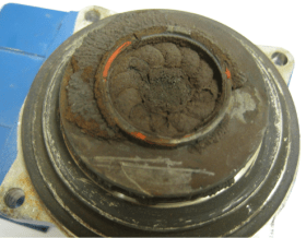
• Debris inside the circulator volute or impeller.
• A closed or partially open isolation valve.
• A failed bushing in the wet rotor circulator.
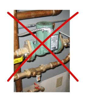
• The wet rotor circulator is mounted with the motor shaft in a vertical orientation (see Figure 4-10b).
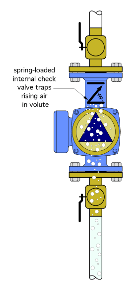
• Air is trapped in the circulator volute and held there by a closed spring check above the circulator volute (see Figure 4-10c).
• A thermostatic mixing valve with a low Cv value is located just upstream of the circulator (see Figure 4-10d).
Things to check:
• Has the system been properly purged?
• What is the water temperature and pressure at the inlet of the circulator?
• Are there any components upstream of circulator that can cause significant turbulence or pressure drop?
• Is there dirt or other debris lodged inside the circulator?
• Is the circulator mounted in vertical pipe with upward flow (see Figure 4-10c)?
• Is the circulator mounted with its motor shaft in a vertical position?
Potential corrective action(s):
• Forced-water purging of the system.
• Increase system pressure to suppress vaporous cavitation.
• Decrease system water temperature to suppress vaporous cavitation.• Provide a minimum of 10 diameters of straight pipe upstream of all circulator inlets.
• Isolate and remove the circulator, disassemble it and check for any debris.
• Change the circulator rotor orientation from vertical to horizontal.
• Use an external spring-loaded check valve installed at least 10 pipe diameters above the circulator outlet, rather than the internal spring-check cartridge, if the circulator is in a vertical pipe pumping upward.
See idronics #15 & #16 for more information on air and dirt separation, and on sizing and locating circulators:
10. SYMPTOM: Significant flow variations depending on which circulators in a multi-circulator system are operating.
Possible cause(s):
• Lack of hydraulic separation between circulators.
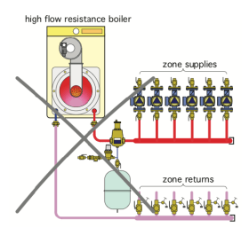
• Several zone circulators drawing flow through a high-flow resistance heat source (see Figure 4-11a).
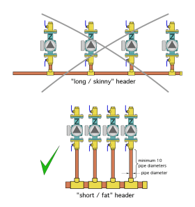
• Using long and small diameter headers to supply multiple zone circulators (see Figure 4-11b).
• Replacement of a low-flow resistance heat source, such as a cast iron sectional boiler, with a high-flow resistance heat source, such as a mod/con boiler with a compact heat exchanger, but without some detail for hydraulic separation.
• An undefined piping configuration created in an attempt to use principals of primary/secondary piping, but without closely spaced pairs of tees for each secondary load.
• Lack of check valves for each circulator when multiple circulators are connected to a common set of headers.
Things to check:
• Does the diameter of the headers limit flow velocities to 2 ft/sec when all circulators served by those headers are operating?
• Is a high-flow resistance heat source piped directly to the headers serving multiple zone circulators?
• Are there circulators supplied from a common set of headers, but without internal check valves or external check valves downstream of each circulator?
• Is the piping a standard configuration or some variant that attempts to morph primary/secondary piping with headers?
• Was an older cast iron sectional boiler replaced with a mod/con boiler having high flow resistance, but without proper hydraulic separation detailing?
Potential corrective action(s):
• Use one of several methods to provide hydraulic separation between all circulators.
a. Use closely spaced tees to create a primary/secondary system.
b. Use a buffer tank with generously sized headers.
c. Use a hydro separator or SEP4™ separator with generously sized headers.
• When replacing a low-flow resistance boiler, such as a cast iron sectional boiler, with a high- flow resistance heat source, use a separate circulator for the new heat source and separate the new heat source and its circulator from the remainder of the system using one of the above methods of hydraulic separation.
• Keep headers as short as possible and size them for a maximum flow velocity of 2 ft/sec.
• Install check valves in each circuit having its own circulator and supplied from the same set of headers.
See idronics #15 for detailed information on hydraulic separation:
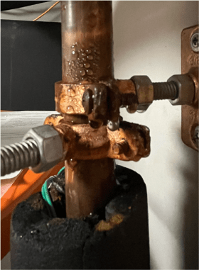
11. SYMPTOM: Condensation on piping or piping components.
Possible cause(s):
• Piping is carrying fluid below the dewpoint temperature of the surrounding air.
• A lack of insulation on chilled water piping (see Figure 4-12a).
• A lack of insulation on components carrying chilled water (see Figure 4-12b).
• Open seams or joints in the insulation allowing surrounding air to contact pipe or other components.
• Cold antifreeze solution is temporarily passing through piping but will eventually warm above the dewpoint of the surrounding air, eliminating the condensation.
Things to check:
• Are there ANY piping or piping components carrying chilled water or chilled antifreeze solution in the system that are not properly insulated and vapor sealed?
• Did a load circuit or zone circuit containing cold antifreeze (i.e., a snow melting circuit or intermittent garage heating circuit) just turn on?
• Is the water seen on the piping or the floor below the piping potentially coming from a leak?
Potential corrective action(s):
• All piping and piping components that transport chilled fluid MUST be properly insulated and vapor sealed to prevent condensation.
See idronics #13 for pipe insulation requirements and installation details for piping in chilled-water cooling systems:
12. SYMPTOM: Corrosion or sludge accumulation inside the system.
Possible cause(s):
• Cast iron or steel piping components are being (incorrectly) used in an “open-loop” system.
• The system contains non-barrier tubing, such as domestic water PEX, polybutylene or early generation rubber tubing.
• The system is experiencing rapid “turnover” of water due to frequent cycling of a pressure-relief valve combined with automatic makeup water.
• The system is experiencing rapid “turnover” of water due to an undetected leak.
Possible causes (continued):
• The system has been intentionally drained and refilled several times based on the belief that doing so is beneficial.
• The system contains degraded glycol-based antifreeze.
• The system has been inadvertently filled with water having a pH less than 7.0.
• Impurities in the water allowed pitting corrosion to develop over time.
• Excessive flow velocities have allowed erosion corrosion to develop over time.
• The system was commissioned while containing large amounts of residual solder flux.
• Use of (unlined) steel expansion tank or panel radiators in an open-loop system.
• Air entering the system through float-type air vents due to improper pressurization.
Things to check:
• If the system is designed as “open-loop,” all components should be copper, brass, bronze, stainless steel or engineered polymer. No cast iron or steel components should be used.
• Has the expansion tank failed due to internal corrosion?
• Does a water sample appear to have a dark or orange color?
• Is there any non-barrier tubing being used in a system that contains cast iron or steel components?
• If antifreeze is used, what is its appearance, smell and measured pH?
• Does the system hold pressure when the automatic makeup water assembly is turned off? If not, a leak is likely somewhere in the system.
• Is there evidence of frequent opening of the pressure- relief valve?
• Does a tested sample of the system fluid indicate acidity (e.g., pH < 7.0)?
• Do any float vents or screens in the flow path show evidence of a greasy residue (e.g., solder flux)?
Potential corrective action(s):
• Replace any cast iron of steel components in open-loop systems with stainless steel, brass, bronze or engineered polymer equivalents.
• Drain and flush the system with a hydronic detergent. Refill with demineralized water.
• Find and correct any leaks.
• If the system uses antifreeze, test the fluid annually for pH and reserve alkalinity.
• If extensive areas of non-barrier tubing are present, and in reasonable condition, isolate those portions of the system using a stainless steel heat exchanger.
• Verify that the system’s expansion tank is functioning properly and is not “water-logged.”
See idronics #18 for detailed information on water quality in hydronic systems:
13. SYMPTOM: Corrosion on the exterior of the piping components.
Possible cause(s):
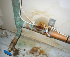
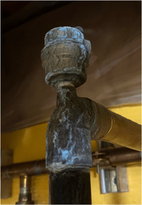
• Solder flux left on piping and fittings creating a blue/green patina (see Figure 4-14a).
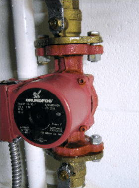
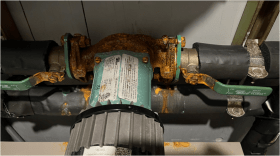
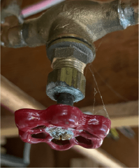
• Weepage from loose valve packings or a circulator flange gasket.
• Steel or iron piping or components joined directly to copper (causes oxidation of the iron or steel).
• Oxidation of cast iron or steel surfaces due to condensation in chilled-water or geothermal-loop systems (see Figure 4-14b).
Things to check:
• Are there any greasy, sticky pipe or fitting surfaces near soldered joints?
• Is there a bluish/green patina surface oxidation on copper pipes or fittings?
• Are there white crusty deposits on valve stems or bodies (see Figure 4-14c)?
• Is there evidence of leakage from float-type air vents (see Figure 4-14d)?
• Are there any connections where steel or cast iron components are threaded directly to copper components?
• Are there any uninsulated steel or cast iron components in a chilled-water system?
Potential corrective action(s):
• Use detergent and water to remove all greasy solder flux from exterior surfaces of piping and components. Wipe the pipe surface clean.
• Clean any patina scaling from copper surfaces with a wire brush.
• Gently snug the bonnet nut on any valves showing signs of weepage.
• Use a brass union or other brass component to transition between copper and cast iron or steel.
• Replace or repair float-type air vents that show signs of leakage.
• Carefully fit elastomeric insulation to any components carrying chilled water or other fluids at temperatures lower than the dewpoint of the surrounding air. Ensure that all seams or joints in the insulation are sealed.
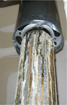
14. SYMPTOM: Corrosion of the venting system.
Possible cause(s):
• Return water temperature to the boiler is below the dewpoint of the flue gases causing them to condense in the venting and the chimney.
• Leakage at joints in the vent piping.
• Proximity to cleaning chemicals, pool disinfectant or anything containing chlorine.
• High sulfur content in the fuel oil.
• Higher than necessary excess air in the combustion process.
• Precipitation leaking down the chimney.
Things to check:
• Measure inlet water temperature to the boiler when it is operating at or close to steady state conditions. Inlet water temperature below approximately 130oF can cause flue gases to condense.
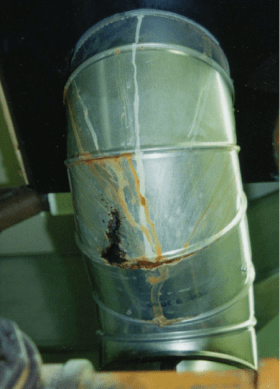
• Inspect all galvanized vent connector piping between the boiler and the chimney. Are there any signs of corrosion (see Figure 4-15a)?
• Is there a “male” crimp joint facing upward in the galvanized steel venting? If so, condensation formed in the vent piping above the joint can leak onto the exterior surface of the vent piping below the joint (see Figure 4-15b).
• If the fuel oil is 500 ppm sulfur, switch to a low-sulfur fuel oil at 15 ppm max.
• Are there any pool chemicals, bleaches or other materials containing chlorine located near the boiler? If so their vapors can cause acids to form in the combustion chamber.
• Are there any signs of deterioration of the masonry chimneys?
Potential corrective action(s):
• Install an “anti-condensation” mixing valve such as a Caleffi ThermoProtec on any conventional boiler exhibiting sustained flue gas condensation.
• Seal all joints in the vent piping with a suitable high- temperature sealant.
• Replace leaking gaskets in the positive pressure venting pipe.
• Remove any materials containing chlorine from the proximity of the boiler.
• Provide outside air for combustion directly to the boiler.
• Replace any galvanized steel vent connector piping that shows signs of corrosion.
• Verify the correct air/fuel ratio of the combustion system to reduce the cooling of flue gases within the venting or the chimney.
See idronics #7 and #10 for more information on protecting boilers from sustained flue gas condensation:
15. SYMPTOM: Slow or inaccurate system response to changing temperatures.
Possible cause(s):
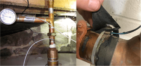
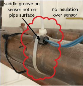
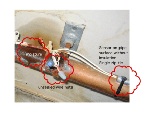
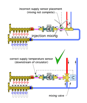
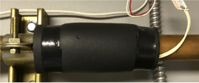
• A temperature sensor that’s incorrectly mounted (see Figures 4-16a,b,c).
• A surface-mounted sensor mounted with the “saddle” groove not on the pipe surface. (See Figure 4-16b).
• A temperature sensor that’s incorrectly located (see Figures 4-16d).
• A poor electrical connection between the sensor leads and the cable leading to the controller.
• Electrical interference affecting the sensor circuit.
• Out-of-range sensor resistance versus temperature.
• Surface-mounted sensors that are not covered with insulation.
• High resistance caused by small diameter and excessively long sensor cables.
• A loose connection of the sensor cables to the controller terminals.
• Shorted or open sensor circuits.
• Controller settings.
Things to check:
• Verify that all surface-mounted sensors are in tight contact with the pipe surface and covered by insulation that extends at least 2 inches on either side of the sensor (see Figure 4-16e).
• Are the zip ties holding the sensor to the pipe intact and are they rated for the highest temperature that the pipe might reach?
• Are there any sensors that fit loosely into the sensor wells?
• Is there any sign of corrosion or loose connections where the sensor leads join the cables?
• Are there any sensor leads or cables running parallel and close to the AC wiring or near motors or transformers?
• Are there any sensors that are immersed in condensate within a well (typically on chilled-water applications)?
• Measure the resistance of suspect sensors when their temperature is stable and compare to the manufacturer’s resistance vs. temperature chart.
• Verify that all sensor cables are of suitable diameter (gauge number), and that they are not longer than allowed by the manufacturer.
Potential corrective action(s):
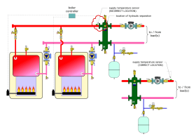
• Be sure that the sensor mounting location is correct relative to the mixing points, circulators, heat sources, etc. When mixing is involved, mount the sensor in a location several inches downstream of the mixing point to ensure flow is fully mixed before passing by the sensor (see Figures 4-16d and 4-17).
• Use two temperature-rated zip ties to secure a temperature sensor to the pipe surface.
• Cover strapped-on sensors with a minimum 3/8” thick elastomeric foam insulation sleeve that extends at least 2” on either end of the sensor housing, and seal the ends of the sleeve to the pipe to prevent air entry (see Figure 4-16e).
• Use thermal paste to bridge any small air gap between the sensor housing and the inside of the sensor well.
• Replace the sensor if its measured resistance is more than 2% in error of the manufacturer’s resistance versus temperature curve.
• Use gel-filled compression connectors to bond the sensor leads to the cable.
• If the sensor cable must run parallel to and within a few inches of the AC wiring, use a twisted pair cable or shielded cable rather than a thermostat cable. Ground the shield layer on one end of the cable.
• When the sensor is mounted in a well on a chilled-water application, be sure the end of the well is sealed against water or water vapor entry.
• Check controller settings for potential adjustments to speed up or slow down controller response.
16. SYMPTOM: The heat source is short cycling.
Possible cause(s):
• The heat source is excessively oversized relative to the load.
• Insufficient flow through the heat source to carry away heat production (“flow bottleneck”).
• Inability of the distribution system to dissipate the rate of heat production (“thermal bottleneck”).
• Differential of the controller operating boiler is set too low.
• Lack of thermal mass in the distribution system.
• An undersized or fouled heat exchanger between the heat source and the load.
Things to check:
• What is the DOE heating capacity rating of the boiler, or nominal heating capacity of the heat pump, relative to a properly done design heating load estimate for the building?
• What is the temperature rise across the heat source when it is operating at or near steady state conditions?
• What is the total heat dissipation ability of the distribution system when supplied at the outlet water temperature of the heat source?
• What is the difference between the “on” temperature and “off” temperature of the heat source when it is enabled to operate (e.g., the operating differential of the controller managing the heat source)?
• If the system has a buffer tank, is it functioning properly? Is it piped correctly?
• Is there a heat exchanger between the heat source and the load? If so, is it sized properly and are its internal surfaces clean?
• Are there any Y-strainers in the flow path between the heat source and the load? If so, are the internal screens in the Y-strainers clean?
• Is the temperature sensor for the boiler controller in a system with hydraulic separation mounted downstream of the point of hydraulic separation (see Figure 4-17a)?
Potential corrective action(s):
• Single hydronic heat sources should not be sized greater than 10% above a properly estimated design heating load.
• Consider a staged heating plant with multiple heat sources if a wide range of heating capacity is needed.
• Consider a modulating heat source (mod/con boiler or heat pump with a variable-speed compressor) if a wide range of heating capacity is needed.
• Consider adjusting the modulation rate of the heat source if possible.
• Verify that the flow rate across a boiler is not less than 1 gpm per 10,000 Btu/hr of heating output (which would yield a nominal 20 F temperature rise). For heat pumps, the suggested flow rate is 2–3 gpm per ton (1 ton = 12,000 Btu/hr) of heat production.
Potential corrective actions (continued):
• Check for anything that could limit flow rate through the heat source (such as several independently operated zonevalves piped to a header directly connected to the heat source).
• Consider controls that coordinate the operation of multiple thermostats to help level the load.
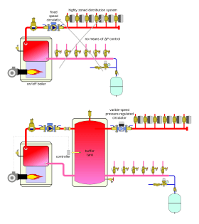
• Add thermal mass between the heat source and load in the form of a buffer tank (see Figure 4-17b).
• Use a boiler reset controller with an “auto differential” function to control on/off heat sources. Auto differential widens the on/off differential of the heat source as the load decreases under warmer outdoor temperatures.
• Increase the on/off differential of the controller operating an on/off heat source.
• Consider options to partially reduce the firing rate of a boiler (i.e., reduce nozzle size on the oil burner, orifice change on gas-fired boilers, etc.). Verify what’s possible with the boiler manufacturer.
• Install controls that manage multiple load schedules to help level the load.
See idronics #17 for information on thermal mass and buffer tanks in hydronic systems:
17. SYMPTOM: Insufficient heat output from the heated wood-framed floor.
Possible cause(s):
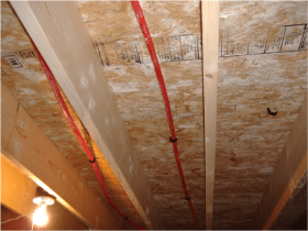
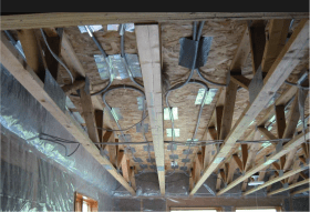
• Lack of aluminum heat transfer plates (e.g., “plateless stapleup”, see Figure 4-18a).
• Poorly fitted or installed heat transfer plates (see Figure 4-18b).
• High thermal resistance above the plates (subfloor and underlayment layers, padding, carpet, etc.).
• Lack of sufficient underside insulation below the tubing and plates.
• Sole reliance on bubble foil insulation below the tubing and plates (insufficient R-value).
• The supply water temperature setting is too low.
• The tube spacing is too wide for the required rate of upward heat transfer.
• Low flow rate in the tubing circuit.
• Leakage of outside air into the joist cavities where the tubing is located.
• Air temperature below the underside insulation is too low.
• Flow blockage due to kinked tubing.
• Lack of supplemental heat if load requires an average floor surface temperature above 85ºF.
Things to check:
• Are there properly installed aluminum heat transfer plates?
• What are the material layers (and total R-value of those layers) located between the bottom of the subfloor and the top of the finish floor?
• What is the R-value of the insulation under the tubing?
• What is the temperature of the space located under the underside insulation?
• What is the flow rate through the tubing circuit?
• What is the supply water temperature to the tubing circuit?
• What is the tube spacing (12” is generally considered maximum, with 8” spacing preferred for this type of installation)?
• Is there outside air leaking into the joist cavities?
• Does the space under the heated floor overheat at the same time that there is inadequate heat output to the space above the floor? This is indicative of insufficient underside insulation.
• Is there a thermostatic mixing valve with a low Cv rating used to supply reduced temperature water to the radiant floor circuits?
Potential corrective action(s):
• Install aluminum heat transfer plates to the as-found “plateless” installation.
• Increase the underside insulation R-value to a minimum of 10 times the total R-value of materials above the plates.
• Verify adequate flow rate in the circuit and suggest a maximum circuit temperature drop of 20oF under steady state design load conditions.
• Consider increasing the supply water temperature after verifying that the heat source and remainder of the installation can operate at a higher temperature.
• Be sure that no outside air can infiltrate into the heated joist cavities at the rim joist and sill locations.
• If a thermostatic valve with a low Cv rating is creating a high pressure drop, replace it with a valve having a Cv rating approximately equal to the desired flow rate through the valve to the radiant circuits.
18. SYMPTOM: A “banging” noise coming from a panel radiator equipped with a thermostatic valve.
Possible cause(s):
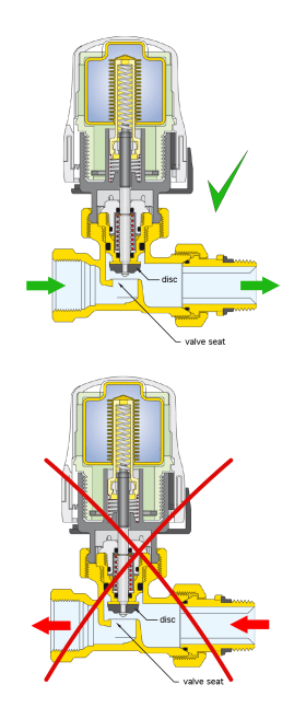
• Flow direction through the radiator valve is backwards, causing unstable movement of the valve disc over the valve seat, especially at low flow rates.
• Use of a fixed-speed circulator without a means of differential pressure control.
• Use of a “high head” circulator.
• Higher than necessary setting of the differential pressure bypass valve.
• Higher than necessary ∆P setting of a pressure-regulated circulator.
Things to check:
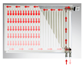
• Is the flow passing through a radiator with an integral valve in the correct direction (so that flow “pushes” against the disc of the radiator valve? (Most radiators with closely spaced bottom supply and return connections, and integral valves, have their inlet connection on the left, as shown in Figure 4-19a).
• If an external radiator valve is present, does the flow arrow on the valve body correspond to the flow direction through the valve (see Figure 4-19b)?
• What is the required ∆P across the circulator when all radiator valves served by that circulator are fully open (requires some calculations)?
• If a differential pressure bypass valve is present in the system, what is its ∆P setting?
• If a pressure-regulated circulator is used, what is its ∆P setting?
• If a “high head” circulator is used, why was it selected?
Potential corrective action(s):
• Change piping connections to ensure flow through the radiator valve is in the correct direction.
• Reduce the ∆P setting of the differential pressure bypass valve.
• Reduce the ∆P setting of the pressure-regulated ∆P circulator.
• Change the fixed-speed circulator from a “high head” model to a circulator with a “flat” pump curve.

