The term heat emitter applies to any hardware used to release heat from water into a space to be heated. Some simple hydronic systems use only one type of heat emitter. More complex systems can have two or more types of heat emitters. When evaluating an existing system, it’s important to identify the types of emitters used and have a general understanding of how their output is affected by the water temperature and the surrounding air temperature at which they operate.
This section discusses the basic thermal performance characteristics of several types of heat emitters, including:
- Fin-tube baseboard
- Cast iron radiators
- Fan-coils and air handlers
- Panel radiators
The piping that connects these heat emitters together also emits heat, and as such, affects the total heat output of the circuit. The calculations described below also assume the heat emitters are clean, unobstructed and free of damage. When evaluating existing buildings, always check the condition of the equipment in occupied spaces. Here are some common existing conditions that can reduce heat output:
- Damage to fin-tube baseboards in high-traffic areas, typically bent/compacted fins from accidental impact
- Radiators covered by decorative woodwork
- Panel radiators that have dust or other debris blocking convective airflow
- Furniture placed in front of supply or return grills on convectors or fan-coils
THERMAL PERFORMANCE OF FIN-TUBE BASEBOARD
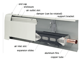
Fin-tube baseboard, such as shown in figure 2-1, is one of the most common heat emitters used in North American residential and light commercial hydronic systems.
Fin-tube baseboard had its origin in the 1930s as a new competitor to cast iron radiators. At that time, boilers operating at relatively high water temperatures were used in almost all hydronic heating systems. These combustion-based heat sources were capable of heating water to high temperatures with minimal effect on their efficiency.
Fuels were relatively inexpensive as fin-tube baseboards gained market share. High water temperatures allowed shorter lengths of baseboard to achieve a given heat output, and thus reduced installation costs.
A footnote that often accompanies a fin-tube rating table states that the ratings include a 15 percent “heat effect factor.” When conceived decades ago, this factor was meant to boost the tested heat output by 15 percent to account for the baseboard being installed at floor level, where surrounding air temperatures were often significantly cooler than air temperatures higher in the room. Today’s homes do not have such drastic room air temperature stratification, and as such, the heating effect factor is not appropriate. Conservative design practice is to divide any heat output ratings that include the heating effect factor by 1.15 to remove it and use the corrected value when sizing the baseboard.
Based on typical rating tables similar to figure 2-2, one might assume that a fin-tube baseboard cannot operate at water temperatures under 150ºF. This is not the case. Any heat emitter will release heat as long as the fluid inside it is warmer — even slightly — than the surrounding air temperature.
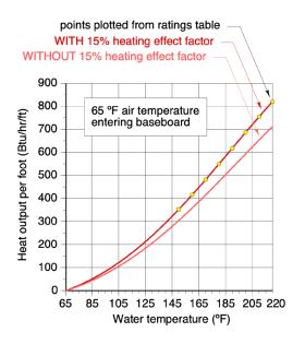
Figure 2-3 shows a graph of the heat output per foot of fin-tube length for typical residential grade fin-tube baseboard as a function of the average water temperature in the fin-tube, and assuming an air temperature of 65ºF at floor level.
The lower curve is based on removing the 15 percent heating effect factor from the manufacturer’s ratings.
Although the outputs are relatively small, the curves on this graph show some heat output even at water temperatures barely above the 65ºF assumed floor-level air temperature.
The lower curve on the graph can be very helpful in evaluating the potential performance of fin-tube baseboard in systems operating at low water temperatures and supplied by contemporary heat sources, such as hydronic heat pumps, mod/con boilers and thermal storage systems.
Example: A baseboard manufacturer lists the output of their fin-tube baseboard as 680 Btu/hr/ft at an average water temperature of 200ºF. That rating includes the 15 percent heating effect factor. Use figure 2-3 to estimate the output of a 12-foot length of that baseboard when operated at an average water temperature of 105ºF, and assuming air enters the baseboard at 65ºF.
Solution: First remove the 15% heating factor by using the lower curve in figure 2-3. Draw a line up from 105ºF on the horizontal axis until it meets the curve. Then draw a line to the vertical axis to read an output of approximately 100 Btu/hr/ft. Finally, since the baseboard is 12 feet long, its total output under the stated conditions would be about 12 ft x 100 Btu/hr/ft = 1200 Btu/hr.
It’s also possible to estimate the heat output of a fin-tube at different entering water and air temperatures using Formula 2-1.
Formula 2-1:
$$q \approx\ a(T_w - T_{air})^{1.4}$$
Where:
q = heat output of fin-tube per unit of length (Btu/hr/ft)
a = a number to be found from rating data or figure 2-3 (Btu/hr/ºF)
Tw = average water temperature in baseboard (ºF)
Tair = air temperature entering baseboard (ºF)
1.4 = an exponent
The value of (a) in Formula 2-1 needs to be “calibrated” for a specific make and model of baseboard. This is done by choosing an output rating about midway between the highest and lowest ratings on the chart, removing the 15 percent heating effect factor (if the footnote with the rating chart indicates it’s included), and then putting all the known values into a rearranged form of Formula 2-1:
Formula 2-1 (rearranged):
$$ a = {q \over(T_w - T_{air})^{1.4}}$$
Example: The rating chart in figure 2-2 indicates a heat output of 510 Btu/hr/ft at an average water temperature of 180ºF. Assume that the 15 percent heating effect factor is included in this rating. Estimate the true heat output rate of the fin-tube if operated at an average water temperature of 110ºF in a basement where the air temperature entering the baseboard is 58ºF.
Solution: First, remove the 15 percent heating effect factor:
$$q_{corrected}={510 \over 1.15}=443 {Btu\over hr \bullet ft}$$
Next, find the value of (a) by putting the data from the rating table into the rearranged form of Formula 2-1:
$$ a={q \over (T_w - T_{air})^{1.4}}={443 \over 252.6}=0.577$$
Finally, use Formula 2-1 along with the new operating conditions, and value of (a) to get the estimated heat output.
$$q \approx a(T_w - T_{air})^{1.4} \approx 0.577(110-58)^{1.4} =145.7{Btu \over hr \bullet ft} $$
Estimating Heat Output of Cast Iron Radiators
Many older hydronic systems have cast iron radiators. The physical design of such radiators varies widely. The two most common configurations are “column-type” and “tube-type” radiators. Both types consist of multiple cast iron sections that are joined together to create the overall radiator. Cast iron sections are made with different heights and widths, but a given radiator is assembled using identical sections.
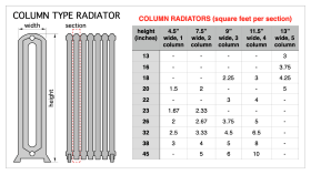
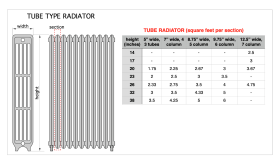
To determine the total heat output of a given cast iron radiator, multiply the square footage surface area of each section (from figure 2-4 or 2-5) by the number of sections in the radiator, and then use Formula 2-2.
Formula 2-2:
$$Q = 0.3748 (A_{total})(T_w -T_{room})^{1.3}$$
Where:
Q = heat output from radiator (Btu/hr)
Atotal = total surface area of all sections in radiator (ft2)
Tw = average water temperature in radiator (ºF)
Troom = air temperature surrounding radiator (ºF)
1.3 = an exponent
Example: determine the heat output of a tube-type cast iron radiator having a section height of 32 inches, a section width of 7 inches, and made using 10 sections. The average water temperature in the radiator is 115ºF, and the room air temperature surrounding the radiator is 70ºF.
Solution: From figure 2-5, the surface area of each section of this radiator is 3.5 ft2. The total surface area is 10 x 3.5 = 35 ft2. Putting this value and the other stated conditions into Formula 2-2 yields:
$$Q=0.3748 A_{total} (T_w - T_{room})^{1.3}=0.3748(35)(115-70)^{1.3}=1850 {Btu \over hr}$$
Estimating Heat Output of Fan-Coils & Air Handlers
The heat output of “fan-forced” convectors (e.g., fan-coils & air handlers) is approximately proportional to the difference between the temperature of the fluid entering the coil and the temperature of air entering the coil. This can be mathematically described using Formula 2-3.
Formula 2-3:
$$Q=c(T_f-T_{air})$$
Where:
Q = rate of heat output (Btu/hr)
c = a constant to be determined for a specific fan-coil or air handler (Btu/hr/ºF)
Tf = temperature of fluid entering coil (ºF)
Tair = temperature of air entering coil (ºF)
Because they are produced in many styles and sizes, the only way to determine the value of “c” is to insert a rating point from the manufacturer into Formula 2-3.
Example: An air handler is rated by its manufacturer to output 50,000 Btu/hr when the water temperature entering the coil is 140ºF and the air temperature entering the air handler is 65ºF. Determine the value of “c” for this air handler.
Solution:
$$c={50,000 {Btu \over hr} \over (140^ \text{o}F - 65^ \text{o} F)} = 667 {Btu \over hr \bullet ^\text{o}F}$$
Once the value of “c” is determined, the output of the air handler can be estimated for other entering fluid and air temperatures.
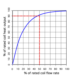
Further “corrections” to estimated heat output may be possible based on the type and extent of performance data provided by the manufacturer. For example, the heat output of any fan-coil or air handler will increase as the flow rate through the coil increases. This happens because higher flow rates increase the average fluid temperature within the coil, and thus increase its heat transfer rate. When the coil is operating at typical flow rates suggested by the manufacturer, the gain in heat output at higher flow rates is relatively small. However, if the coil is operating at flow rates well below nominal suggested conditions, the change in heat output can be substantial and must be accounted for. Some manufacturers may provide correction factors for such conditions.
One “approximation” that describes the change in heat output of a coil as a function of flow rate, assuming the constant entering fluid and entering air temperatures, is that the coil will attain about 90% of its rated heat output when operated at about 50% of its rated flow rate. Figure 2-6 shows a typical relationship between heat output from a coil and flow rate.
Other hydronic heat emitters have similar relationships between heat output rate and flow rate. The “non-linear” characteristic of the graph representing this relationship shows that operating any heat emitter at abnormally high flow rates produces very little thermal benefit. Doing so also substantially increases pumping power requirements.
Estimating Heat Output of Panel Radiators
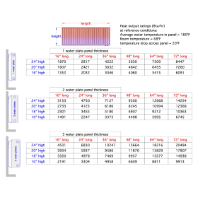
In North America, it is common to find the heat output of panel radiators based on an average water temperature of 180ºF, and assumed room air temperature of 68ºF. Figure 2-7 shows an example of a typical rating table, where the heat output is based on this temperature difference (e.g., 180 - 68 = 112ºF).
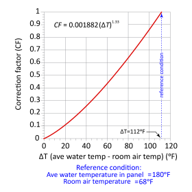
It’s possible to estimate the heat output of panel radiators at other average water temperatures and surrounding air temperatures using the graph in figure 2-8.
To estimate heat output, first determine a value for the difference between the average water temperature in the panel radiator and the surrounding room air temperature. Find the value on the horizontal axis. Follow a vertical line up to the red curve, and then a horizontal line to the vertical axis. The value on the vertical axis is a correction factor.
Multiply the rated heat output from figure 2-7 (which is based on 180ºF average water temperature, and 68ºF room air temperature) by the correction factor from figure 2-8 to get the estimated heat output at the new condition.
Example: Determine the heat output of a double water plate panel radiator that is 24 inches high and 48 inches long, when operated at 110ºF average water temperature and 70ºF surrounding room air temperature.
Solution: The difference between average water temperature and room air temperature is (110ºF - 70ºF) = 40ºF. From the graph in figure 2-8, the correction factor is approximately 0.26. The table in figure 2-7 lists the output at the reference conditions to be 9,500 Btu/hr. So, the output at the lower water temperature condition is (0.26) x 9,500 = 2,470 Btu/hr.
Although the heat output at the lower water temperature is only about one quarter of the output at the reference condition, that output is still adequate to heat a room of about a 250 square foot floor area having a design heating load of 10 Btu/hr/ft2.
Panel radiators can work well with low-temperature heat sources, such as hydronic heat pumps and mod/con boilers. Large panels are required at lower water temperatures.
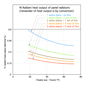
As the average water temperature decreases, the percent of heat leaving a panel radiator as radiant output rather than convective output increases. This is beneficial, since radiant output helps warm surrounding surfaces, increasing the mean radiant temperature of the room. Figure 2-9 shows the percentage of total heat output that is radiant heat for different panel radiator configurations and as a function of the difference between average water temperature and surrounding room air temperature.
Figure 2-9 shows that the highest ratio of radiant heat output is provided by panel radiators without fins. As fins are added, the amount of heat leaving the panel due to convection increases and radiant heat output decreases. Using panels with more fins always increases total heat output.


