This Section discusses specific details that allow heat exchangers to perform as expected in several types of applications.
HEAT EXCHANGER FOULING
To maintain peak performance, it’s important to minimize the potential for fouling films to form on any heat transfer surfaces. Fouling can be the result of unintentional chemical interactions within the system. It can also occur due to dirt or other debris unintentionally present in the system.
CHEMICAL FOULING
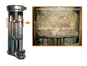
Fouling films can form on heat exchanger surfaces due to fluid chemistry issues. For example, the solubility of minerals such as calcium and magnesium in water decreases as water temperature increases. If water containing these minerals passing along the internal surfaces of a heat exchanger becomes hot enough to reach the maximum solubility limit of the dissolved minerals, they will precipitate out of solution and form scale on those surfaces. The higher the surface temperatures, the greater the potential for scale formation. Figure 5-1 shows an example of the heat exchanger from a modulating/condensing that has been severely scaled from minerals in the system water.
The best approach for reducing scaling of heat exchanger surfaces is to demineralize the system water. Demineralization is done by passing water through a column containing thousands of small porous polymer beads that are chemically formulated to capture positive and negative ions in the system water. These undesirable ions include positively charged cations of calcium (Ca++), magnesia (Mg++) and sodium (Na+). They also include negatively charged anions of chlorine (Cl-) and carbonate (CO- -). When the resin beads capture these cations and anions, they release hydrogen cations (H+) and hydroxide anions (OH-). The released ions instantly bond to form pure H2O.
idronics 18 provides more details on demineralizing water in hydronic systems
DEBRIS FOULING
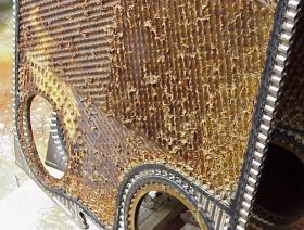
Most hydronic systems are assembled from components that have been stored, transported and handled multiple times between manufacturing and installation. During these times, debris such as road dust, insects, pollens, drywall dust, solder balls, metal chips and sawdust can enter these components. These materials can accumulate on the internal surfaces of heat exchangers and significantly reduce heat transfer rates. These accumulations can also increase the pressure drop through components, resulting in lower flow rates, which further reduce heat transfer. Figure 5-2 shows a heavily fouled plate from a plate & frame heat exchanger.
Although some of the heat exchangers discussed earlier in this issue can be disassembled for cleaning, that process is difficult, time consuming and expensive. The heat exchanger must be isolated, disconnected from piping, disassembled, cleaned, reassembled and put back in service. In large systems, this could take several days and will prevent heating or cooling operation in any portion of the system involving the heat exchanger during that time.
Severely fouled brazed plate heat exchangers, or sealed shell and coil heat exchangers, may need to be replaced. Again, a costly and time-consuming process.
The best way to avoid these situations is to minimize the possibility of debris entering heat exchangers. This can be done by installing high-performance separators that capture dirt and magnetic particles upstream of the heat exchanger.
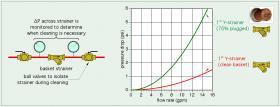
Some designers, by default, specify wye strainers as a means of capturing dirt particles in the system. While this approach is partially effective, it does have limitations. One is that the pressure drop through a wye strainer increases significantly as debris collects on the internal strainer basket, as shown in Figure 5-3. The increased pressure drop decreases flow in the circuit, which negatively impacts the heat transfer performance of any heat exchanger.
Another limitation of wye strainers is that they must be isolated and disassembled for cleaning. This requires temporary shutdown of the circuit and some minor drainage of system fluid.
Finally, wye strainers do not capture magnetic particles such as magnetite that form when dissolved oxygen in the water fluid reacts with steel or cast iron components in the system. Magnetite will be attracted to magnetic fields generated by circulator motors, especially the strong fields generated by permanent magnets in wet rotor circulators with electronically commutated motors.
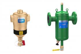
The modern alternatives to wye strainers are low-velocity zone separators equipped with removable magnets. Figure 5-4 shows examples of Caleffi DIRTMAG™ separators for both small and larger system applications.
Low-velocity zone dirt separators do not allow the dirt they capture to accumulate in the flow path, and thus create far less pressure drop than wye strainers. They can also be flushed without shutting down the circuit. Some dirt separators are available with strong permanent magnets that can capture very fine iron oxide particles formed from ferrous metals in the system.
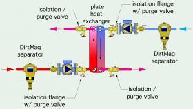
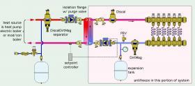
These DIRTMAG separators should be installed upstream of heat exchangers, as shown in Figure 5-5.
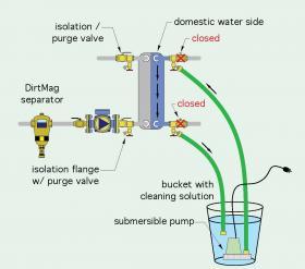
The component arrangement shown in Figure 5-5 has the DIRTMAG separators upstream of both the heat exchanger and the circulators supplying it. A combination isolation flange/purge valve is shown on the outlet of each circulator. These flanges allow the circulator to be isolated and removed if necessary. In combination with isolation/purging valves on the outlet ports of the heat exchanger, they also allow each side of the heat exchanger to be isolated and flushed with a cleaning solution if necessary.
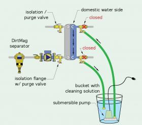
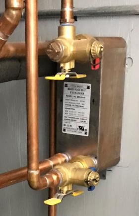
A combination isolation/purging valve, rated for use with potable water, is installed at each port on the domestic water side of the heat exchanger. The inline balls of these valves are closed to isolate the heat exchanger from the other domestic water piping. The cleaning solution is circulated through the domestic water side of the heat exchanger to dissolve and remove mineral scale. The two hoses can also be reversed to change the direction of the cleaning solution through the exchanger. After the cleaning solution has been sufficiently circulated and drained, the heat exchanger should be flushed with domestic water to remove any residual cleaning solution.
HEAT EXCHANGERS SUPPLYING ANTIFREEZE-PROTECTED CIRCUITS
When a heat exchanger is installed as the “heat source” for a portion of the overall system, that portion is fully isolated from the remainder of the system. As such, it must include components used in all closed-loop hydronic systems. These include a pressure-relief valve, expansion tank, pressure gauge, provisions for filling and purging, and one or more separators to remove air, dirt and magnetic particles. Optional components include a flow meter and thermometers or temperature sensor wells to monitor the inlet and outlet temperatures of the heat exchanger. In some applications, specifically district heating systems, heat meters are also installed on the closed circuit served through the heat exchanger.
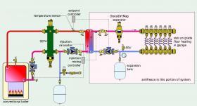
Figure 5-8 shows a configuration of these components for a situation in which the heat exchanger supplies a garage floor heating system that operates with an antifreeze solution. The heat source is assumed to be a convention boiler.
Whenever a conventional boiler is supplying a low temperature heat emitter system, that boiler should be protected against sustained flue gas condensation. Consider that a garage floor slab that has not operated for several days during the winter could be very cold — even below 32ºF — when this portion of the system starts operating. The very cold antifreeze solution returning from the floor circuits poses two “threats” to the system. One is that it could freeze the water on the primary side of the heat exchanger. Given the rapid response of a brazed plate heat exchanger, and its low water content, ice crystal can form quickly — in some cases, in less than one minute. Any delay in getting heat to the primary side of the heat exchanger increases the possibility of freezing. A failure of the circulator responsible for circulating heated water through the primary side of the heat exchanger could also lead to freezing.
One way to protect against this situation is to install a temperature setpoint controller that monitors the temperature of water leaving the primary side of the heat exchanger. When this temperature rises to some setpoint deemed sufficient to verify that heat is being transferred to the heat exchanger, this controller turns on the circulator for the antifreeze side of the heat exchanger.
The other “threat” posed by a very cold slab is sustained flue gas condensation in a conventional boiler. Keep in mind that the rate of heat transfer to a very cold slab could be significantly higher than under normal operation. Heat exchangers will “transmit” this high rate of heat flow back to the heat source.
One approach to protecting the boiler is to use an injection mixing controller to regulate the temperature of the antifreeze solution supplied to the floor circuits. This controller also monitors the inlet temperature to the boiler and reduces the flow of hot water to the primary side of the heat exchanger, when necessary, to prevent sustained flue gas condensation. A motorized 3-way mixing valve and suitable controller is another option that can provide both supply temperature control and boiler protection.
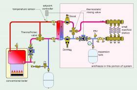
Another approach to this scenario uses two thermostatic mixing valves, as shown in Figure 5-9.
The 3-way mixing valve on the right side of the heat exchanger regulates the supply temperature to the floor circuits. It is important to select this mixing valve with a Cv rating close to the total flow rate required by the manifold station. This will limit the pressure drop across the mixing valve to approximately 1 psi. A Caleffi ThermoProtec™ valve on the left side of the heat exchanger limits hot water flow through the primary side of the heat exchanger, as necessary, to keep the boiler inlet temperature high enough to prevent sustained flue gas condensation.
When the heat source is a heat pump, electric boiler or mod/con boiler, it is not necessary to using mixing devices in the system. Figure 5-10 shows a representative configuration.
The heat exchanger should be selected so that it can supply the design heating load to the floor circuits while operating at an approach temperature drop of no more than 5ºF. This allows the heat source to operate just a few degrees F above the supply temperature of the floor circuits. Low operating temperature improves the efficiency of mod/con boilers and heat pumps.

