This section describes several common applications, as well as some “novel” applications for heat exchangers in hydronic heating and cooling systems. Conceptual piping diagrams are presented for these applications. Designers need to determine the suitability of the concepts, as well as the required specifications of the heat exchangers, piping, circulators, etc., for specific applications. References to other issues of idronics are given to provide further design assistance.
SNOW & ICE MELTING (SIM) SYSTEMS
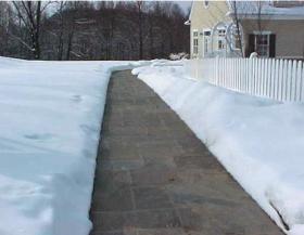
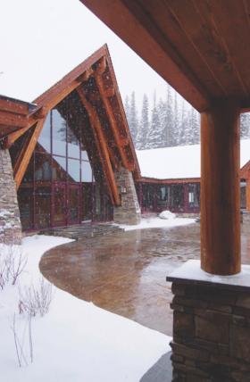
The use of hydronics technology for snow and ice melting dates back to the mid-1900s, when copper tubing was embedded in exterior pavements. Today, PEX, PERT and PEX-AL-PEX tubing provides a reliable way to distribute heat from a boiler to exterior pavements such as sidewalks, steps, driveways, emergency room arrival areas and even complete parking lots.
SIM systems are categorized based on how they are expected to perform relative to snow fall rates and subsequent melting times.
Class 1 SIM systems are commonly used for residential walkway and driveway areas. They deliver heat to pavement at rates between 80 and 125 Btu/hr/ft2. These rates are not necessarily high enough to melt snow as it falls, especially during strong storms. Several hours may be needed to completely melt the snow, especially when the system starts from a cold condition.
Class 2 SIM systems are generally sufficient for pavements at retail and commercial sites. They deliver heat at rates between 125 and 250 Btu/hr/ft2. This class of SIM can usually melt snow as it falls — once the pavement is up to normal operating temperature.
Class 3 SIM systems are for the most demanding applications where pavements must remain free of snow and ice at all times. Examples include steeply sloped exterior ramps at parking garages and hospital emergency room entrances. Typical heat delivery rates range from 250 to 450 Btu/hr/ft2.
Some SIM systems are single purpose. They are designed solely for snow and ice melting. These systems are usually supplied by one or more boilers. The entire system operates with an antifreeze solution, and no heat exchangers are needed between the boiler(s) and distribution system.
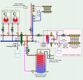
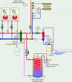
In other systems, snow and ice melting is one of several loads served by a common heat source. The other loads are typically space heating and domestic water heating. In these systems, a heat exchanger is often used to separate the SIM subsystem from the remainder of the system. This allows the majority of the system to operate with water rather than antifreeze. Figure 6-2 shows a representative configuration.
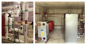
Figure 6-3 shows portions of snowmelting systems supplied through plate & frame heat exchangers.
POOL HEATING
Installations in which a boiler or hydronic heat pump supplies space heating in winter and year-round domestic hot water often have plenty of available heating capacity between the end of one heating season and the beginning of the next. If the property has a pool, that available heating capacity can be used to maintain it at comfortable conditions. Figure 6-4 shows how a heat exchanger specifically designed for pool heating can be installed.
This system is very similar to the one in Figure 6-2. The SIM subsystem from Figure 6-2 has been replaced by a pool heating subsystem.
Most heat exchangers intended for pool heating use a shell & tube design, which is better suited to higher flow rates needed for pool filter systems. Water from the heat source passes through the shell of the heat exchanger, which can be made of steel, cast iron or cast brass, and is part of the closed-loop system. Pool water passes through the tube bundle, which is typically made of titanium or titanium alloyed with stainless steel to resist the corrosive effects of highly chlorinated pool water.
The subsystem shown in Figure 6-4 uses the pool filter pump to move pool water through the tube bundle in the heat exchanger. Bypass piping is shown along with a manually operated bypass valve. The shell side of the heat exchanger is also piped to CPVC unions and ball valves. This detailing allows the heat exchanger to be removed from service if necessary, while still maintaining the ability to circulate pool water through the filter.
Swimming pool water temperature is typically maintained between 75 and 90ºF. This relatively low temperature allows heat sources such as mod/con boilers and hydronic heat pumps to operate at high efficiencies — assuming that the heat exchanger is sized for a “tight” approach temperature difference of perhaps 5ºF.
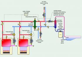
If one or more conventional boilers are used as the heat source, it is important to protect the boiler(s) from sustained flue gas condensation. This can be done using Caleffi ThermoProtec™ valves on the boiler(s), as shown in Figure 6-5.
Swimming pools have very high thermal mass. Without proper detailing, this mass can “dominate” the water temperature in the system, possibly preventing other subsystems that may be operating at the same time from meeting their respective loads. This condition must be avoided.
One approach is to use controls that make pool heating a lower priority load relative to domestic water heating. Thus, if the domestic water-heating load is active, flow to the primary side of the pool heat exchanger is temporarily suspended. This is essential if the boilers are programmed to operate at higher water temperatures during the domestic water-heating mode.
Another method is to use a “temperature-controlled” variable-speed circulator to supply water to the primary side of the pool heat exchanger. The speed of this circulator is controlled based on the water temperature leaving the hydraulic separator. If that temperature is below some predetermined value — deemed necessary to allow proper operation of other loads — the speed of the circulator decreases. This reduces the rate of heat transfer to the primary side of the pool heat exchanger. If the temperature is above this setpoint, the circulator operates at full speed. This detail is also shown in Figure 6-5.
DOMESTIC WATER HEATING
The most common method of heating domestic water in hydronic systems that also supply space heating is by using an indirect water heater. Figures 6-2 and 6-4 show how such a water heater would be installed as a subsystem.
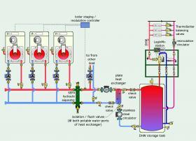
Indirect water heaters use internal coil heat exchangers. The rate at which they can transfer heat to the domestic water is typically limited by natural convection on the outer surface of the coil heat exchanger. In applications requiring very high rates of heat transfer, it may not be possible to find an indirect water heat with sufficient heat transfer capacity. In these situations, the use of a properly sized brazed plate heat exchanger can meet the heat transfer requirements. Figure 6-6 shows a possible piping configuration for this approach.
Assume that the water in the upper portion of the tank needs to be maintained at 140ºF. The stainless steel brazed plate heat exchanger would be sized to transfer the full output of the multiple boiler system with the water temperature supplied from the boilers at 145ºF. Assuming a nominal 20ºF temperature drop through the primary side of the heat exchanger, the 5ºF approach temperature difference keeps the boilers shown in Figure 6-5 operating at inlet water temperatures that produce some flue gas condensation, and thus an incremental increase in efficiency.
Combination isolation/flushing valves are installed on each domestic water port of the heat exchanger. These valves allow that side of the heat exchanger to be periodically isolated and flushed with a cleaning solution to remove scaling.
A stainless steel circulator is used between the heat exchanger and storage tank. The circulator supplying boiler water to the heat exchanger can be cast iron, since it is part of the closed-loop system. Designers must ensure that these circulators, as well as the associated piping, are sized for flow rates that can transfer the full output of the boiler system to the domestic water tank when necessary.
Assuming a 20ºF temperature change across the primary side of the heat exchanger (e.g., 145ºF entering down to 125ºF leaving), the flow rate into the primary side must be 67.5 gpm. This will require a 2.5” copper tube to maintain a reasonable flow velocity.
A commercially available sizing software suggests that the minimum heat exchanger for this heat transfer requirement is a 10” x 20” x 50 plate brazed plate unit. At this flow rate, the pressure drop through that heat exchanger is about 1.7 psi ( about 4 ft. of head). Assuming that the other components and piping between the hydraulic separator and heat exchanger add 5 feet of head, the selected circulator needs to provide a minimum of 67.5 gpm at 9 feet of head. This will likely require a light commercial class circulator, not a small zone circulator. If the wire-to-water efficiency of that circulator is estimated at 30%, the estimated input power to the circulator would be about 380 watts.
Unfortunately, there have been systems where an undersized circulator, along with undersized piping, have created flow “bottlenecks” in this approach to high-capacity domestic water heating. Flow bottlenecks cause heat transfer bottlenecks. The latter can severely limit the heat transfer rate between the boilers and domestic hot water. Under these conditions, the boilers will quickly reach their high limit settings and short cycle. The boiler plant may have sufficient heating capacity for this high demand DHW load, and the heat exchanger may have sufficient heat transfer capacity, but without adequate flow, the overall process can be severely limited.
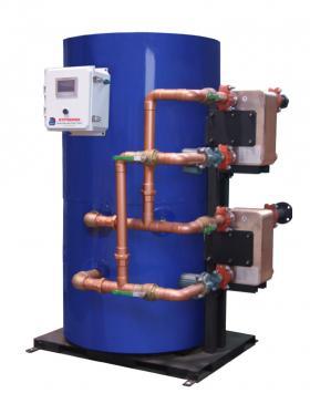
Pre-engineered and pre-assembled products that use external brazed plate heat exchangers in combination with domestic hot water storage tanks are available for high-volume commercial applications. Figure 6-7 shows one example.
ON-DEMAND DOMESTIC WATER HEATING
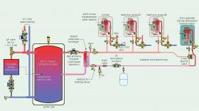
Another approach to domestic water heating uses a brazed plate heat exchanger sourced from a buffer tank, or a boiler system, to create domestic hot water literally seconds before it is required at a fixture.
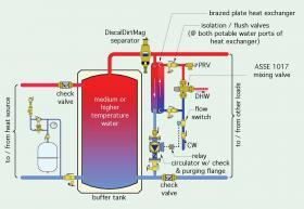
The assembly shown in Figure 6-8 can be used in residential and light commercial systems that have a heated buffer tank. That tank may be associated with renewable heat sources, such as solar thermal collectors, biomass boilers or heat pumps. It could also be heated by a fossil fuel boiler.
When the domestic hot water drawn by the plumbing distribution system exceeds 0.7 gpm, a flow switch, rated for use with domestic water, closes it contacts. This energizes the coil of a relay, which turns on a circulator to draw hot water from the top of the buffer tank through the primary side of the heat exchanger. After passing through the heat exchanger, this flow returns to the lower portion of the buffer tank. Cold domestic water flows through the secondary side of the heat exchanger in a counterflow direction, absorbing heat from the primary side.
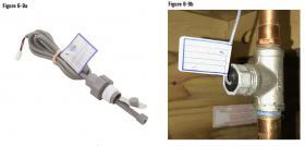
Figure 6-9a shows an example of a flow switch suitable for use with domestic water. The switch closes its contacts at flow rates of 0.7 gpm or higher and opens its contacts at flow rates of 0.4 gpm or less. This switch is designed to thread into a 3/4” stainless steel tee, as shown in Figure 6-9b.
The high surface area-to-volume ratio of the brazed plate heat exchanger, combined with a minimal amount of piping connecting it to the buffer tank, allows heated domestic water to be available within 3 to 5 seconds of the flow switch contact closure.
This is significantly faster than the response time required by a gas-fired tankless water heater. This approach also has the advantage of not storing domestic hot water when it is not operational, which reduces the potential for Legionella growth.
The system shown in Figure 6-8 assumes that the water in the buffer tank is maintained hot enough to fully heat the domestic water on a single pass. This may or may not be the case, depending on the heat source, the space heating emitters, the required domestic hot water delivery temperature and the sizing of the heat exchanger. When the thermal storage tank is relatively hot, and the heat exchanger is sized for a close-approach temperature difference, there is no need for a temperature boost after the domestic water leaves the heat exchanger. An ASSE 1017 point-of-distribution mixing valve should always be installed to protect the fixtures from hot water delivery temperatures over 120ºF.
This application is a good example of when a heat exchanger with a high thermal length, as discussed in Section 4, is appropriate. The domestic water needs to undergo a large temperature change, but the LMTD between the two fluids will be relatively small. This type of application will favor a brazed plate heat exchanger with relatively long plate length.
This configuration includes two isolation/flushing valves installed at both domestic water ports of the heat exchanger. These valves allow the heat exchanger to be isolated from the rest of the domestic water system and flushed with a cleaning solution, as described in Section 5.
Another detail is the use of two spring-check valves adjacent to the buffer tank. The check valve near the upper left connection prevents reverse thermosiphoning between the buffer tank and heat source. The valve in the lower right limits heat migration into the return side of the space-heating circuits at times when space heating is not required.
The brazed plate heat exchanger and its associated piping should be kept as close to the buffer tank as possible. This minimizes the amount of system water that needs to be displaced at the start of a DHW draw and helps keep the response time to only a few seconds. The heat exchanger and its associated piping should also be insulated to reduce heat loss to the mechanical room.
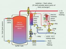
Figure 6-10 shows an extension of this approach. An electric tankless water heater has been added to boost the final DHW delivery temperature when necessary. This configuration would be useful when the buffer tank operates at temperatures below the required delivery temperature for DHW. In this case, the heat exchanger can still provide significant preheating, leveraging the low starting temperature of cold domestic water. Combination isolation/flushing valves are also installed on the piping connected to the tankless water heater to allow isolation and cleaning. It would also be possible to use a tank-type water heater to provide the final temperature boost.
Another variation on this approach to domestic water heating is shown in Figure 6-11.
This system uses a brazed plate heat exchanger to transfer heat from a buffer tank to a recirculation loop serving several DHW loads. The system shown in Figure 6-11 is based on use of a renewable energy heat source, such as a heat pump,
Several DHW load points are connected to the recirculation loop. Each is equipped with a point-of-use tankless electric water heater, which would provide the temperature boost required by each DHW load. Each tankless heater can be individually operated, and each can have a different delivery temperature setpoint.
If the water in the recirculation loop reaches a temperature equal to or above the DHW delivery temperature of one or more of the tankless heaters, the heating elements in those heaters do not operate.
The tankless heater and 3-way diverter valve at the far end of the recirculation loop is solely for thermal disinfection. Once each day, the diverter valve is powered on to direct flow through this tankless heater, which has a setpoint of 140ºF. This raises the temperature of the recirculation loop and holds it there for at least 30 minutes to kill any Legionella bacteria in the recirculation loop. Hot water drawn from this loop during the disinfection cycle passes through the ASSE 1070 point-of-use anti-scald mixing valves, which limit temperature to the fixtures to 120ºF. After the thermal disinfection cycle is complete, the dedicated tankless heater is powered off, and the diverter valve directs flow around it. The tankless heater used for thermal disinfection only needs to be sized to the heat loss of the recirculation system when operating at peak disinfection temperature. This may only be 3 or 4 kilowatts, depending on the amount of piping used and how it is insulated.
It is important to insulate all portions of the recirculation system, including the heat exchanger, to limit heat loss into the building.
The brazed plate heat exchanger would be sized for a tight approach temperature difference. It should be capable of transferring the full heat output rate of the renewable energy heat source when the tank is at its minimum temperature.
The buffer tank is configured in a “2-pipe” configuration. The piping supplying warm water for low-temperature space-heating tees into the tank headers just upstream of the tank. A differential pressure valve is used in the heat source circuit to provide minimum forward opening pressure of 1 to 1.5 psi. This prevents water returning from the space-heating distribution system from passing through the heat source when it is not operating. It also replaces the need for a check valve to prevent reverse thermosiphoning between the buffer tank and heat source.
If the renewable energy heat source supplying the buffer tank is turned on and off automatically, as would be the case with a heat pump or pellet boiler, that on/off operation must be based on the temperature of the water in the tank.
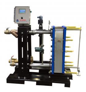
The concept of on-demand domestic water heating using an external heat exchanger can also be scaled up to high-volume commercial applications. Figure 6-12 shows one example of a pre-engineered, pre-assembled system that uses high-temperature boiler water in combination with a plate & frame heat exchanger for high-volume domestic water heating.
The product shown in Figure 6-12 includes a modulating control valve to control boiler water flow through the primary side of the heat exchanger, and thus regulate domestic water delivery temperature. It also has controls, a stainless steel recirculation circulator, strainers and pressure-relief valves.
A final thought on the use of brazed plate or plate & frame heat exchangers for domestic water heating. Some practitioners argue against this practice. The common retort is that hard water can scale such heat exchangers. While this is a possibility, it’s also a possibility with internal coil heat exchangers, especially when the latter are operated at high internal temperatures to force a given rate of heat exchange through a relatively small surface area.
Most indirect water heaters have permanently installed internal coil heat exchangers. When the exterior surface of that coil is scaled, there is no practical way to clean it. This is not the case with a brazed plate heat exchanger equipped with the combination isolation/flushing valves shown in several figures involving domestic water within heat exchangers. If the scaling is beyond the point where chemical cleaning can correct it, the brazed plate heat exchanger can be replaced. When the domestic water side of the internal coil heat exchanger is heavily scaled, the entire indirect tank needs to be replaced, which is typically much more costly.
Hard domestic water will scale any heat exchanger operating at temperatures high enough to cause dissolved minerals to precipitate out of that water. The hardness needs to be reduced through softening, or the scaling problems will persist, regardless of the type of heat exchanger used.
HEAT EXCHANGERS FOR NON-PRESSURIZED THERMAL STORAGE TANKS
Some renewable energy heating systems, such as those supplied by pellet-fired boilers or cordwood gasification boilers, require several hundred gallons of thermal storage. In some systems, that storage is provided by pressure-rated, ASME-listed steel tanks. These tanks are expensive, and due to their size, the logistics of moving them into place within a mechanical room can be challenging, and sometimes even impossible. One solution is the use of a “panelized,” non-pressurized tank that can be moved into the mechanical space in pieces and then assembled.
Non-pressurized thermal storage tanks are vented to the atmosphere. As such, they are “open” to absorption of oxygen from the atmosphere. Although it is possible to design a hydronic system that can connect directly with a non-pressurized tank, there are several limitations to this approach that are not present in a “closed” hydronic system.
One issue is that any steel or cast iron components connected to the water in the non-pressurized tank would be subject to severe corrosion due to the higher dissolved oxygen content of the water. There are chemicals called oxygen scavengers that can partially compensate for this corrosion, but the concentration of these chemicals must be monitored and maintained, which unfortunately doesn’t always happen. This can cause premature failure of expensive hardware, including boilers, circulators, radiators and other components made of carbon steel or cast iron.
A better solution is to separate the water in a non-pressurized thermal storage tank from both the steel boiler and any ferrous metal in the distribution system. This can be done using internal coil heat exchangers mounted within the storage tank, as discussed in Section 2. It can also be done with external brazed plate heat exchangers. Of these choices, the latter provides several advantages including:
- Forced convection on both sides of the heat exchanger for much higher convection coefficients, and the ability to achieve the necessary heat transfer rates using smaller heat exchanger surface area.
- The ability to accurately estimate the performance of the heat exchanger. It is difficult to find detailed performance models for internal coil heat exchangers operating over a wide range of conditions.
- The ability to service or replace the heat exchanger if ever necessary without opening the thermal storage tank.
- The possibility of using a single heat exchanger for both heat input and heat extraction from the tank.
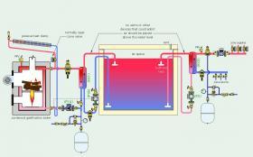
The system shown in Figure 6-13 uses two brazed plate heat exchangers: One between the cordwood gasification boiler and the thermal storage tank, and the other between the tank and the distribution system.
The boiler-to-tank heat exchanger (HX1) is sized to transfer the boiler’s maximum rate of heat output to the tank water with only 5ºF approach temperature difference between the water entering the heat exchanger from the boiler, and the water leaving it for the tank.
Circulator (P1A) runs at a constant speed whenever the boiler is enabled to operate. A variable-speed stainless steel circulator (P1B) provides flow between the heat exchanger and tank. The speed of this circulator varies in response to the boiler inlet temperature. At boiler inlet temperatures below 130ºF, circulator (P1B) is off. Its speed ramps up as boiler inlet temperature climbs above 130ºF, reaching full speed at an inlet temperature of 140ºF. This control action prevents the boiler from operating with sustained flue gas condensation.
The pipe carrying hot water from heat exchanger (HX1) passes through the tank wall above the water line and terminates in a bullhead tee. This releases water horizontally and helps preserve beneficial temperature stratification within the tank.
Circulator (P1B) is mounted low relative to the water level inside the tank. This increases the net positive suction head available to the circulator and helps prevent cavitation. This is important because the water at the top of the tank is at zero gauge pressure and can be very hot. Both of these conditions decrease the margin against cavitation.
The piping that’s slightly above the water level in the tank will be under slight sub-atmospheric pressure. There should not be any air vents, valves or other devices in this piping that could potentially allow air to enter the piping.
Purging flanges are installed on both ports of circulator (P1B). These allow water to be forced into the piping to displace air when the system is commissioned.
The details between the tank and load side heat exchanger are similar to those on the heat input side. Circulator (P2) is also a stainless steel circulator.
A variable-speed pressure-regulated circulator provides flow to the zoned distribution system.
Because there are two completely isolated closed-loop portions within the overall system, two pressure relief valves, two expansion tanks and two make-up water assemblies are required. The expansion tanks can be relatively small because they only service their respective closed-loop sub-systems. The expansion and contraction of water within the tank simply changes the water level slightly.
This system requires two heat exchangers between the heat source and the heat emitters. There must be some temperature drop across each of these heat exchangers to create the necessary rates of heat transfer. These temperature drops should be kept small (suggested values of not more than 5ºF). The lower the temperature drop across heat exchanger (HX2), the lower the temperature of the thermal storage tank can get while still being able to satisfy the heat transfer requirements of the heat emitters. This can prolong the discharge cycle of the tank and reduce the number of boiler firings required.
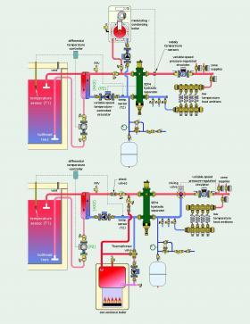
Figure 6-14 shows two possibilities for adding an auxiliary boiler or re-pipe an existing boiler to the system shown in Figure 6-13.
The distribution system shown in Figure 6-14 serves low-temperature heat emitters. If a conventional boiler is used, it should be protected against sustained flue gas condensation by a Caleffi ThermoProtec valve. This high flow-capacity mixing valve automatically blends hot water leaving the boiler with cool water returning from the distribution system so that the water entering the boiler is at or above some minimum temperature. A typical minimum inlet temperature for a gas-fired boiler is 130ºF.
The speed of circulator (P2) is regulated to maintain a desired supply water temperature to the heat emitters. This detail also limits the supply water temperature to the heat emitters if and when the thermal storage tank is at a relatively high temperature.
When the thermal storage tank cannot contribute heat to the system, circulator (P2) would be off. The boiler circulator would be turned on whenever the boiler is operating. Check valves are used to prevent flow through the heat exchanger when circulator (P2) is off, or through the boiler when it is off.
Figure 6-14 also shows a differential temperature controller in both systems. This controller is energized whenever one or more zones are operating. It monitors the temperature difference between the water near the top of the thermal storage tank at sensor (T1), and the water returning from the distribution system at sensor (T2). Circulator (P2) is allowed to operate when one or more zones is operating, and the temperature at sensor (T1) is 8ºF or more above the temperature at sensor (T2). When this temperature difference drops to 5ºF or less, circulator (P2) is turned off. This control action prevents heat created by the auxiliary boiler from being inadvertently transferred into the thermal storage tank. The on and off settings for the differential temperature controller can be adjusted based on the operating characteristics of the distribution system and the approach temperature difference across heat exchanger (HX2).
DISTRICT HEATING
There are situations where it’s desirable to heat several buildings from a central heat plant, rather than use individual heat systems within each building. Examples include college campuses, multiple apartment buildings in close proximity or groups of retail stores forming a shopping center. This can be done using a district heating system.
Most district heating systems have a central boiler plant where all heat is generated. That heat could come from fossil fuel boilers, renewable heat sources such as biomass boilers or a combination of these heat sources. The boiler plant typically is configured as a multiple boiler system to provide capacity control and provide redundancy if one boiler is down for service.
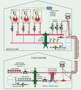
Heat from the boiler plant is distributed to multiple “client” buildings through insulated underground piping. The layout of this distribution piping depends on the locations of the client buildings. When the buildings are located along a street, a 2-pipe direct return piping system is typically used and installed parallel with the street. When the buildings form a cluster around the boiler plant, a homerun piping distribution system is appropriate. Figure 6-15 shows an example of the latter, with one of three client buildings represented.
In this system, heat is generated by three modulating/condensing boilers. Assuming that each boiler has a 10:1 turndown ratio, this provides a wide range of heat output capability, specifically a 30:1 system turndown ratio. This helps maintain good efficiency under partial load conditions.
The boilers supply hot water to the SEP4™ hydraulic separator, which provides air, dirt and magnetic particle separation. It also isolates the pressure dynamics of the boiler circulators from the variable-speed circulators that provide flow to the client buildings.
Circulator (P1) is one of the distribution circulators. Its speed is based on temperature feedback from sensor (S2) on the supply side of the client building’s distribution system. The controls for the system strive to maintain a target temperature at sensor (S2). That temperature could be a setpoint or based on outdoor reset control. If the measured temperature at sensor (S2) is below the target value, the speed of circulator (P1) is increased, and vice versa. This control action reduces pumping energy to the minimum needed for the current load in the client building.
A plate & frame heat exchanger is used to isolate the boiler plant and underground piping from the distribution system in the client building. This heat exchanger is fully insulated to minimize heat loss. This prevents a potential leak or servicing requirement on the client side of the heat exchanger from disrupting service to the other client buildings. This heat exchanger is provided with valves for isolation and flushing if necessary.
The left side of the heat exchanger, and all components connected to that side, form a closed-loop system that is completely separated from the boiler plant and underground piping. As such, this portion of the system requires a pressure relief valve, expansion tank, make-up water assembly, circulator and provisions for air, dirt and magnetic particle separation. These functions are provided by Caleffi SEP4 hydraulic separators.
Two CONTECA™ heat-metering systems are shown in this system. The one in the boiler plant monitors all heat leaving the plant to the client building. The heat- metering system in the client building monitors all heat arriving at the building from the district system. The difference in readings between these two heat-metering systems would give the thermal loss in the underground piping. Some district systems may only need one of these heat-metering systems, depending on how the thermal losses of the underground piping will factor into the energy charges for the client buildings.
idronics #24 elaborates on the benefits of heat metering in hydronic systems.
Flow in the client building’s distribution system is provided by a variable-speed pressure-regulated circulator (P2). The speed of this circulator automatically adjusts as the zone valves in the client building open and close.
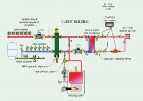
There are many possible variations on this system. For example, one or more of the client buildings may have an existing boiler that could provide heat to the building if the district system was down. One piping design that could accommodate this existing boiler is shown in Figure 6-16.
Zoning within the client building might use multiple circulators rather than zone valves. Some district systems can also be designed to provide chilled water cooling in summer as well has heating in winter.
HEAT INTERFACE UNITS
Another application that relies on brazed plate heat exchangers uses centralized heat production, or district heating, to supply space heating and domestic hot water for a multi-unit building containing apartments, condominiums, office spaces or retail shops. Heat from a central “plant” or district system is transported throughout the building using a 2-pipe distribution system. A third pipe carrying cold domestic water is routed along with these two pipes. At each building unit, the three pipes connect to a compact assembly called a heat interface unit (HIU). The heat passing from the 2-pipe building distribution system into each HUI is accurately metered. Each unit within the building is then charged for the thermal energy they use. The HIU also meters the total domestic water used.
Heat exchangers are a critical component within HIUs. They allow the primary water supplied from the building’s central heat plant to be separated from the water used for space heating or domestic hot water within each unit. The separation of heating plant water from domestic water is an obvious requirement. The separation of heating plant water from the water used for space heating within each unit ensures that a potential leak in the space-heating subsystem within that unit can be isolated and repaired without disrupting service to other units served by the central heating plant.
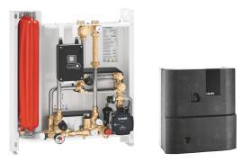
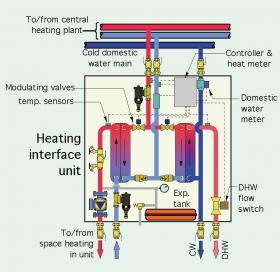
Figure 6-17 shows an example of a modern HIU that uses two brazed plate heat exchangers — one for space heating and the other for heating domestic water.
The HIU is mounted within a wall cavity in the building unit, close to the distribution pipes from the central plant. It has connections for the heating supply and return pipes, as well as one connection for cold domestic water.
When space heating is required, a modulating valve within the HIU regulates the flow of hot water from the central plant through the primary side of one brazed plate heat exchanger. This flow regulation is based on maintaining a desired supply water temperature leaving the secondary side of the heat exchanger and supplying the unit’s space-heating distribution system.
A flow switch detects when there is a demand for domestic hot water. A second modulating valve then regulates flow from the central plant through the primary side of a second brazed plate heat exchanger. The flow regulation is based on providing a desired domestic hot water temperature leaving the secondary side of the heat exchanger.
The total space heating and domestic hot water energy used is based on the flow rate and temperature drop of the central plant water from where it enters and leaves the HIU. The controller within the HIU records the total thermal energy used.
For more information on heat metering, see idronics #24.
The HIU shown in Figure 6-17 also includes a circulator and expansion tank for the space-heating distribution system within the building unit.
Figure 6-18 shows a conceptual piping arrangement for an HIU that provides the functions just described. It does not show exact hardware devices or their placement.
HIUs allow individually metered thermal energy for space heating and domestic hot water without the need for combustion heat sources within each unit. This reduces cost and increases safety by eliminating the need for gas piping and venting of combustion appliances dispersed throughout a building.
LAKE WATER COOLING
At depths of approximately 40 feet or more, the water temperature in lakes, located in climates with cold winters, remains relatively constant at about 39ºF. Water at this temperature is ideal for chilled-water cooling, if it can be accessed from shore.
The potential to use direct lake source cooling for smaller buildings depends on several factors. First, the building must be located close to a lake, and such that the intake pipe can be located at a sufficient depth to extract cool water. Ideally, the intake pipe would be at least 30 feet beneath the lake surface. However, lesser depths may be possible depending on the water temperatures required by the cooling system.
Second, the project must conform to any regulations regarding use of lake water. Different requirements may apply to “navigable waters” versus lakes in which boating is not allowed. Compliance checks should be done at the onset of a feasibility study to rule out possible restrictions that would prevent further consideration of this approach.
If regulations allow further pursuit of the project, water temperature measurements should be taken at several depths below the lake surface during late summer to assess available water temperatures during months when cooling is needed. This will help in determining the required depth of the water intake pipe.
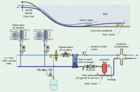
Assuming the project reaches the design phase, Figure 6-19 shows one possible method for “harvesting” cool lake water for building cooling. This system uses readily available components.
A shallow well pump provides flow for the lake piping. This pump might be within the building being cooled or a separate building closer to the lake. If water remains in the system during winter, the pump and piping must be protected against freezing. Shallow well pumps are limited in their ability to lift water above the surface of the lake. If the lift requirement is not more than approximately 20 feet above the lake surface, and the piping to and
Shallow well pumps are limited in their ability to lift water above the surface of the lake. If the lift requirement is not more than approximately 20 feet above the lake surface, and the piping to and from the lake is sized for low head loss, a shallow well pump should suffice. The objective is to keep the pump as low as possible, relative to the lake surface.
Lake water is drawn into a foot valve at the end of a high-density polyethylene (HDPE) pipe. The end of this pipe and foot valve are secured to a concrete ballast block that prevents the pipe from floating. This ballast block also suspends the foot valve above silt on the lakebed. Depending on the length of pipe required, it may be necessary to use additional concrete ballast blocks to ensure the piping in the lake stays on, or close to, the lakebed. The piping must make the transition to shore at depths that prevent the water it contains from freezing in winter.
The incoming lake water passes into an automatic filter. This device monitors the differential pressure across its inlet and outlet ports. When the pressure differential reaches a set value, the filter initiates an automatic cleaning cycle. In this mode, a typical automatic filter needs a minimum flow of 30 gpm at 30 psi pressure to provide proper cleaning. This flow is provided from a separate water source routed through a pilot-operated solenoid valve that opens simultaneously with the waste valve on the filter. The accumulated sediment is washed off the internal stainless steel screen and blown out through a waste pipe. A filtering criterion of 100 microns is suggested to minimize any accumulation of sediment within the heat exchanger. The frequency of filter operation depends on the characteristics of the lake. If the intake pipe is located deep within a lake that has minimal surface water flow, the intake water should remain relatively clean. However, if the lake water experiences significant weather-related disturbances, the water may be turbid at times, and thus will require more filtering.
Water passes from the automatic filter to the pump. Ideally, this pump should be constructed with a stainless steel volute to provide maximum corrosion resistance. Full port ball valves should be installed to isolate the pump if maintenance is required. A priming line may also be required to add water to the intake pipe when the system is being put into operation.
From the pump, lake water passes into one side of a stainless steel plate & frame heat exchanger. The heat exchanger should be sized so that the approach temperature difference between the incoming lake water and the chilled water leaving the other side of the heat exchanger is not more than 5ºF under design cooling load conditions. Lower temperature rises across the heat exchanger may allow for smaller coils in air handlers, lower flow rates and lower circulator operating costs.
After passing through the heat exchanger, the lake water returns to the lake through another HDPE pipe. Like the supply pipe, the return pipe should be kept on or near the lakebed using concrete ballast blocks. It should discharge into the lake several feet away from the foot valve, and preferably in a direction that carries the water away from the foot valve.
The load side of the heat exchanger connects to a 2-pipe chilled-water distribution system. The ECM-based circulator operates on differential pressure control and changes speed in response to the opening and closing of the zone valves controlling flow to each air handler.
The electrical energy used by the lake water pump could be further reduced by using a variable-speed circulator that responds to either the temperature rise across the lake side of the heat exchanger or to the temperature of the lake water leaving the heat exchanger. Either would allow the flow rate of lake water to be adjusted based on the current cooling load on the other side of the heat exchanger.
The lake water circuit could also be used to supply low-temperature heat to a water-source heat pump for space heating or for domestic water heating.
LAKE PLATE HEAT EXCHANGERS
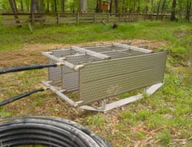
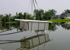
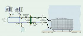
Another method for harvesting the cooling potential of lakes uses a closed plate-type heat exchanger, an example of which is shown in Figures 6-20 and 6-21.
The lake heat exchanger consists of multiple stainless steel plate assemblies. Each assembly has two stainless steel plates that are specially patterned to create flow channels. These plates are welded together along their perimeter. Each plate assembly is connected to a supply and return header. The overall assembly is welded to a stainless steel base that supports the plates several inches above the surface they rest on. HDPE tubing is routed from the headers to the shore.
This type of heat exchanger allows for a completely closed hydronic cooling system. This eliminates the need for the automatic blowdown filter, as well as the flat plate heat exchanger. However, a dirt-separating device designed for a closed hydronic circuit should still be installed to establish and maintain a very low level of suspended solids in the recirculating water. In Figure 6-22, a SEP4 hydraulic separator provides air, dirt and magnetic particle separation. It also allows for different flow rates between the lake heat exchanger and the chilled-water distribution system.
Manufacturers of lake water heat exchangers provide design assistance software that can be used to select a specific heat exchanger based on total cooling load, lake water temperature, flow rate through the heat exchanger and temperature change across the heat exchanger.
As with direct lake water cooling, designers should verify if any regulations prevent the placement of a lake plate heat exchanger, especially in navigable waters, as an initial step in the feasibility of this type of cooling system.
SUMMARY
Heat exchangers add exceptional versatility to modern hydronic systems. They allow physical separation of fluids, but passage of heat, enabling applications such as domestic water heating, snowmelting and pool heating.
Section 4 gives the basis for theoretical performance assessment of heat exchangers. The associated mathematics can be challenging. Most practicing designers now use software available from several heat exchanger manufacturers to narrow the design down to an appropriate heat exchanger model.
To ensure reliable performance, heat exchangers need to be maintained with little if any fouling. The use of demineralized water as well as high-efficiency dirt separators is important.
For more information on demineralized water, see idronics #18.

