Preface
There are several devices that can absorb heat from a room and transfer that heat to a stream of chilled water. Some have been used for several decades, while others are relatively new. Some are delivered to a project ready to be placed on a floor or suspended from a ceiling and then piped to the chilled-water distribution system. Others are integrated into the construction of the building. This section provides a survey of traditional chilled-water terminal units that are intended to handle both sensible and latent cooling loads. Section 7 will cover radiant cooling panels and chilled beams, which are used in systems that separate the sensible and latent cooling loads.
AIR HANDLERS
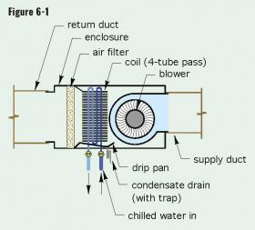
One of the most common chilled-water terminal units is an air handler. A basic air handler consists of a chilled-water coil, condensate drip pan, blower, air filter and enclosure, as illustrated in Figure 6-1.
Air handlers are available in a wide range of rated cooling capacities, ranging from about 1 ton (e.g., 12,000 Btu/hr) to several hundred tons. Smaller air handlers are typically used in highly zoned systems, or systems where it is impractical to route large ducting. Larger air handlers are more common in systems where large cooling loads are present in a single space or a group of adjacent spaces that can be served by a ducted distribution system.
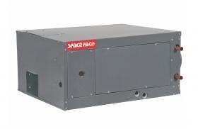
Smaller air handlers used in commercial chilled-water cooling systems are usually configured with a horizontally oriented cabinet, an example of which is shown in Figure 6-2.
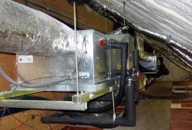
Horizontal air handlers are usually suspended within a mechanical chase above a suspended ceiling. The weight of the air handler and its associated ducting and piping is supported by an overhead structure such as a concrete slab, wood framing or steel trusses. Figure 6-3 shows an example where a small chilled-water air handler is suspended on steel channel strut that is supported by threaded rods attached to a structure ceiling. Each steel rod includes a vibration dampener that minimizes vibration transfer to the structure.
The small air handler in Figure 6-3 is contained within the thermal envelope of the building. This protects the water within the coil from freezing. The air handler is also placed above a secondary drip pan. This is a shallow, sealed metal or plastic pan that is equipped with a condensate drainage pipe. Its purpose is to capture any condensate that might collect if the primary drip pan within the air handler were to leak or the drainage pipe from the primary drip pan were to plug. The goal is to provide maximum protection against condensate leakage in areas above finished spaces. Also notice that all piping to the air handler is insulated to prevent condensation.
Large air handlers in the range of 50 to several hundred tons of cooling capacity are usually highly customized products that are configured to the specific requirements of each project. Their modular construction allows for many more options compared to those available in smaller air handlers. Those options include: chilled-water coils, DX refrigerant coils, heating coils, mixing dampers that can blend outside air with return air, variable-speed blowers that can operate independently to control building pressurization, heat recovery wheels, multiple levels of filtration, UV light sterilization hardware, acoustical suppression and humidifiers. The air handler shown in Figure 6-4 has doors allowing service technicians to work inside the unit. The overall functionality of such complex devices is usually coordinated by a building automation system.
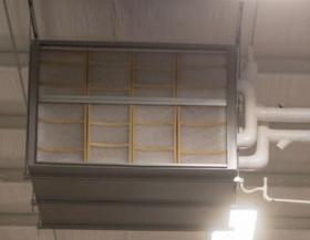
Figure 6-5 shows another commercial air handler mounted from the ceiling structure of a cold storage warehouse. This air handler is non-ducted. The photo shows several air filters on the intake side of the unit. Note the insulated supply and return piping that supply twin chilled-water coils within the air handler. The small piping near the bottom of the unit is a condensate drain equipped with a trap.
“2-PIPE” & “4-PIPE” AIR HANDLERS
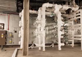
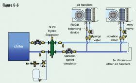
Many air handlers can be ordered in either “2-pipe” or “4-pipe” configurations. A 2-pipe air handler contains a single coil that could be used for either heating or cooling. In heating mode, heated water flows through the coil. In cooling mode, chilled water flows through the coil. Several 2-pipe air handlers are typically combined on a single distribution system, an example of which is shown in Figure 6-6.
Most 2-pipe distribution systems can operate with either heated water or chilled water. However, all air handlers on the distribution system can only operate in the same mode (e.g., heating or cooling) at a given time.
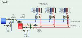
A “4-pipe” air handler is supplied with two coils: one for heating and the other for cooling. Each coil has a supply and return connection to the appropriate distribution mains. A 4-pipe system allows each air handler to operate in either heating or cooling, independent of the other air handlers in the system. Figure 6-7 shows an example of a distribution system using 4-pipe air handlers.
Notice that the heated water and chilled water circuits are completely separated. As such, each should be equipped with make-up water systems, expansion tanks, air/dirt/hydraulic separators and safety devices.
Most air handlers are rated at specific operating conditions for both the incoming chilled water temperature and the incoming air. Those conditions are typically as follows:
• Entering chilled water temperature: 45ºF
• Incoming air conditions
Dry-bulb temperature = 80ºF, wet-bulb temperature = 67ºF
Dry-bulb temperature = 75ºF, wet-bulb temperature = 63ºF
The thermal output ratings for chilled-water air handlers are usually expressed as:
• Total cooling capacity (Btu/hr)
• Sensible cooling capacity (Btu/hr)
Sensible cooling capacity refers to the air handler’s ability to lower the temperature of the air as it passes through the unit. Latent cooling capacity is a measure of the air handler’s ability to remove moisture from the air stream. Total cooling capacity is the sum of sensible cooling capacity and latent cooling capacity. Latent cooling capacity can be obtained by subtracting sensible cooling capacity from total cooling capacity.
Other performance measures for air handlers include:
• Fluid head loss or pressure drop across the coil as a function of the flow rate through the coil.
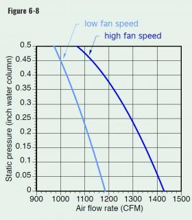
• Airflow rate produced by the blower as a function of the external static pressure of the ducting system. This is typically stated in cubic feet per minute (CFM), versus the static pressure of the duct system, which is stated in inches of water column (e.g., inch w.g.). If the air handler has a multiple-speed motor, this information is often given for each speed setting.
Figure 6-8 shows an example of airflow rate produced by a nominal 3-ton air handler with a 3-speed motor versus the static pressure developed by its blower. The static pressure at which the air handler operates is determined by the design of the ducting system it supplies.
A typical airflow rate for a chilled-water air handler is 400 CFM per ton of delivered cooling capacity.
FAN COILS
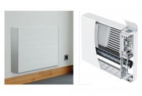
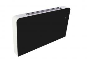
Another commonly used chilled-water terminal unit is called a fan coil. These units can be mounted into a recessed wall cavity or fastened to a wall surface. An example of two surface-mounted “console” fan coils that can be used for chilled-water cooling, as well as hydronic heating, are shown in Figure 6-9.
Like air handlers, fan coils have an internal blower or fan, a chilled-water coil and a condensate drip pan. Some fan coils also have intake air filters. They are designed to deliver cooling (and in some cases heating) to a single room or space, and are not connected to ducting. Fan coils come in a range of capacities, as well as configured for either a 2-pipe or 4-pipe distribution system, as discussed for air handlers. They often have electrical controls that allow for multiple-speed operation of the blower or fan during heating or cooling, or in some cases just the fan for air circulation. Some also have programmable controls.
Most fan coils have very low internal water volume. This allows them to respond to demands for cooling (or heating) very quickly.
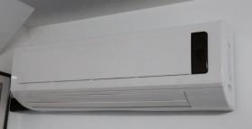
Fan coils equipped with condensate drain pans, and thus suitable for chilled-water cooling, are also available in other mounting configurations. One example is the “high wall” cassette shown in Figure 6-10.
High wall cassettes typically have a small tangential blower that draws air in through the front grill and discharges the cooled/dehumidified air from the bottom slot. The angle at which air is discharged into the room can be varied depending on the unit’s mounting height. This adjustment can often be made using a handheld remote control. All wall cassettes used for chilled-water cooling must be equipped with a condensate drip pan and an associated drainage tube. The drainage line can be routed outside or into the building’s sanitary drainage piping, where allowed by code. In the latter case, the drainage pipe must be equipped with a trap to prevent sewer gas from migrating into the unit.
Designers planning to use fan coils or air handlers need to reference specific thermal, hydraulic and airflow data available from manufacturers. Since these terminal units deliver a cooled and dehumidified air stream, cooling capacity is usually listed in a way that allows sensible and latent cooling capacity to be determined based on the chilled water temperature and flow rate supplied, along with typical indoor air and humidity conditions assumed for the rated outputs.
Cooling capacity increases as chilled water temperature decreases, especially when the supplied chilled water temperature is well below the dewpoint of air entering the terminal unit.
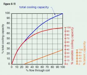
Cooling capacity is also influenced by flow rate. Figure 6-11 shows a typical relationship.
The non-linear relationship between total cooling capacity and flow rate implies that small changes in flow rate at lower flow rate operating conditions have significantly more effect on cooling capacity than will the same change in flow rate at high flow rates. This characteristic is similar to that of hydronic heat emitters operating at a constant supply water temperature.
If a modulating valve will be used to control the total cooling capacity of an air handler or fan coil by controlling flow rate through it, that valve should use an internal flow control element with an equal percentage characteristic.
Figure 6-11 also shows that the sensible cooling capacity of the coil begins to rise at lower flow rates, while the coil’s latent cooling capacity begins at approximately 25% of total flow rate, and rises in a quasi-linear manner with increasing flow.

