Preface
The classic approach to absorbing heat and humidity from occupied spaces is to pass air from those spaces through a chilled-water coil in an air handler. That coil provides both sensible and latent cooling. The extent of total cooling capacity and the proportions of sensible versus latent cooling are constrained by the coil selection, as well as the temperature and flow rates of the chilled water stream and airflow through the coil. This approach “couples” the sensible and latent cooling loads and handles both through a common device (e.g., the coil in the air handler). This approach also delivers both sensible and latent cooling using a forced-air stream, typically delivered through ducting.
Another option that has enjoyed increasing interest over the last two decades, is based on “decoupling” the sensible and latent cooling loads. The majority of the sensible cooling load is handled by absorbing heat into radiant panels built into floors or ceilings, or into devices commonly known as “chilled beams.” This heat absorption occurs above the dewpoint of the interior air, and thus does not create any surface condensation. The remainder of the cooling load (e.g., small portion of the sensible load and all of the latent load) is handled by a chilled-water coil operating at temperatures well below the dewpoint of the interior air. That coil is typically integrated into an air handler that also provides ventilation to interior spaces.
RADIANT PANELS FOR COOLING
The term radiant panel is generally used in the context of heating. It is defined as any temperature-controlled interior surface that releases 50% or more of its total heat output in the form of infrared radiation.
It’s also possible for the temperature of interior surfaces, such as floors and ceilings, to be lowered by circulating cool water through tubing embedded in or fastened to those surfaces. This allows those surfaces to absorb long-wave thermal radiation given off by occupants or other warmer objects in the room. It also allows the surfaces to absorb some of the incident solar radiation entering through windows or skylights.
To avoid condensation, it is critically important that cooled ceilings or floors operate at temperatures above the dewpoint temperature of the spaces they serve. This also applies to components that serve those surfaces, such as piping in a mechanical chase above a cooled ceiling. The chilled water supplied to radiant cooling panels and their associated piping should be a minimum of 3ºF above the current dewpoint temperature of the room. Designers should also consider how the dewpoint temperature varies in different spaces within a building. For example, on a humid day the dewpoint temperature within a frequently used entry vestibule is likely to be higher than that within an interior building space. This is also true for spaces used for food preparation, commercial laundry, washing or exercising. Such areas should be zoned and use independent controls for regulating chilled water supply temperature.
RADIANT FLOOR COOLING
One common radiant panel configuration uses PEX, PERT or PEX-AL-PEX tubing embedded in a concrete floor slab. This approach has been applied in a wide range of commercial and institutional buildings. Due to the thermal mass of the concrete, this approach is often referred to as a “high-mass” radiant panel. This type of panel can be used for heating and sensible cooling.
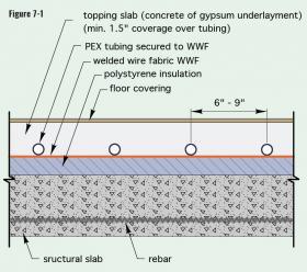
Many multi-story commercial and institutional buildings have structural concrete slab floors. Figure 7-1 shows an example of how a “topping slab” with embedded tubing can be placed on a layer of rigid polystyrene insulation over a structural concrete floor.
A simplified method for estimating the heat absorption from a cooled floor is based on the difference between the average floor surface temperature and the operative temperature of the room. This is expressed as Formula 7-1.
Formula 7-1:
$$ q_c = 1.23 \Bigl( T_o-T_f \Bigr) $$
Where:
$q_c$ = cooling absorption flux (Btu/hr/ft2)
$1.23$ = combined convective+radiative surface coefficient for cooling (Btu/hr/ft2/ºF)
$T_o$ = operative temperature of the room (ºF)
$T_f$= average floor surface temperature (ºF)
The operative temperature of a room is the average between the room’s dry-bulb air temperature and the room’s mean radiant temperature.
Formula 7-2:
$$ T_o = {T_{air} + T_{MR} \over 2} $$
Where:
$T_o$ = operative temperature of the room (ºF)
$T_{air}$ = dry-bulb temperature of air in the room (ºF)
$T_{MR}$ = mean radiant temperature of surfaces in the room (ºF)
A simplified approach for determining the mean radiant temperature (TMR) of a space is given in Formula 7-3.
Formula 7-3:
$$ MRT= \frac{\underset {\mathrm{all\ surfaces}}{\sum\limits}T_i A_i}{\underset {\mathrm{all\ surfaces}}{\sum\limits} \ \ A_i} $$
Where:
$MRT$ = estimated mean radiant temperature of a space (ºF)
$T_i$ = surface temperature of surface (i) in the room (ºF)
$A_i$ = area of surface (i) in the room (ft2)
For a typical rectangular room with 6 surfaces (4 walls, ceiling, floor), Formula 7-3 is just shorthand for the following:
$$ MRT= \frac{\underset {\text{all surfaces}}{\sum\limits} T_i A_i}{\underset {\text{all surfaces}}{\sum\limits} \ \ \ A_i} = { {T_1A_1+T_2A_2+T_3A_3+T_4A_4+T_5A_5+T_6A_6} \over {A_1+A_2+A_3+A_4+A_5+A_6} } $$
When the mean radiant temperature of a room with radiant heating or cooling is calculated, that calculation would be for the unheated or uncooled surfaces. Thus, for a room with floor cooling, the surface temperature of the floor and the area of the floor would not be used in Formula 7-3.
Here’s an example: The mean radiant temperature of a room with floor cooling is determined to be 78ºF. The room’s dry-bulb air temperature is 75ºF. The floor area of the room is 500 ft2. Estimate the rate of heat absorption into a floor, assuming the average floor surface temperature is 69ºF.
Solution: The room’s operative temperature is found using Formula 7-2:
$$ T_o = {T_{air} + T_{MR} \over 2} = {75 + 78 \over 2} = 76.5^\circ F$$
The cooling flux into the floor is calculated using Formula 7-1:
$$ q_c = 1.23 \Bigl( T_o-T_f \Bigr) = 1.23 \Bigl( 76.5-69\Bigr) = 9.2 {Btu \over hr \cdot ft^2} $$
The rate of heat absorption would be the cooling flux multiplied by the floor area:
$$ Q = \Biggl(9.2 {Btu \over hr \cdot ft^2} \Biggr) 500ft^2 = 4600 {Btu \over hr} $$
There is also a relationship between the water temperature in the embedded tubing, the tube spacing and the thermal resistance of any floor covering over the slab. In qualitative terms, the closer the tube spacing, the lower the water temperature, and the lower the thermal resistance of any floor covering, the greater the heat absorption capacity of the cooled slab.
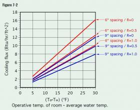
Figure 7-2 shows the relationship between heat absorption flux (in Btu/hr/ft2) and the temperature difference between the operative temperature of the space and the average water temperature in the embedded tubing circuits. Tube spacings of 6 inches and 9 inches are shown, along with floor covering resistances of 0 (bare or painted slab), 0.5 and 1.0 ºF•hr•ft2/Btu.
Here’s an example: A room has a floor area of 500 square feet. The entire bare floor slab has embedded tubing spaced at 9 inches apart. Assume that a room has a dry-bulb air temperature of 75ºF, and that the mean radiant temperature of the space, excluding the cooled floor, is 79ºF. The average water temperature in the tubing circuits (e.g., [supply temperature + return temperature]/2) is 62ºF. Determine the total sensible cooling provided by the floor slab.
The operative temperature of the room is the average of the room’s dry-bulb air temperature and the room’s mean radiant temperature based on all surfaces other than the cooled floor.
$$ T_o = {T_{air} + T_{MR} \over 2} = {75 + 79 \over 2} = 77^\circ F$$
The difference between the room’s operative temperature and the average water temperature in the embedded tubing is:
$$ \Delta T = 77^\circ F - 62^\circ F = 15^\circ F $$
Using the graph in Figure 7-2, the cooling flux is found to be 6.0 Btu/hr/ft2.
The total sensible cooling provided is this cooling flux multiplied by the room area.
$$ Q = \Biggl(6.0 {Btu \over hr \cdot ft^2} \Biggr) 500ft^2 = 3000 {Btu \over hr} $$
RADIANT CEILING PANELS
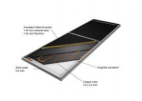
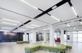
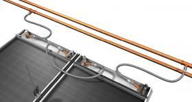
Ceilings are ideal surfaces for radiant cooling. One type of “modular” radiant ceiling panel intended for commercial and institutional buildings is shown in Figure 7-3.
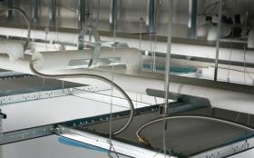
This panel is factory-assembled and can also be installed as a free-hanging “cloud” element below a finished ceiling, or within a typical “T-bar” suspended ceiling grid. These panels are available in nominal widths of 24 inches, and nominal lengths ranging from 24 to 120 inches.
Each panel consists of a painted steel frame pan into which is fitted a copper tube circuit, graphite heat diffusion layers and top-side insulation. The graphite layers provide lateral heat conduction between the tubing and panel areas between the tubing. Although these panels are relatively light, they still require support from light gauge chain or steel cable connected to structural elements such as bar joints or concrete slabs.
The heat absorption rate of modular ceiling panels is also a function of the room’s operative temperature, the average chilled water temperature in the panels, and how the panel is mounted (e.g., flush or “cloud”). The cooling flux for a flush-mounted panel operating with 58ºF entering water temperature, in a room with a 75 ºF dry-bulb temperature, is 30-35 Btu/hr/ft2. Under the same conditions, a “cloud” mounted panel can absorb 40-50 Btu/hr/ft2.
CHILLED BEAMS
Although relatively new in North America, chilled beams have been used for cooling in European buildings for more than four decades. They operate at chilled water temperatures above the room’s dewpoint, and thus can only absorb sensible heat. They must therefore be supplemented by an air-handling system that handles latent cooling (moisture removal).
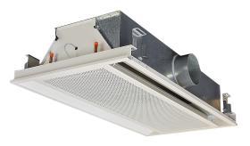
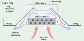
Chilled beams are categorized as “active” or “passive.” Active chilled beams have ventilation air ducted to them. This air has been preconditioned in both temperature and moisture content before it is sent to the chilled beam. This preconditioning allows the air to absorb moisture from the space, and thus manage the latent portion of the cooling load. The preconditioned “dry” air enters the chilled beam and passes through nozzles that increase airflow velocity and decrease local air pressure. The reduced pressure induces airflow through the chilled-water coil, where the temperature of the air is reduced. This reduced temperature air then mixes with the dry ventilation air, and it is reintroduced to the room through the slot diffusers near the outer edges of the chilled beam.
Passive chilled beams do not have ventilation airflow. They are used to supplement heating or cooling capacity in spaces where sufficient ventilation air is introduced through active chilled beams or other means.
Figure 7-8b illustrates the flow of ventilation air into the unit and the induced flow of room air through the coil.
A typical 6-foot-long active chilled beam, when supplied with 58ºF chilled water and 40 CFM of ventilation air, will provide approximately 3,600 Btu/hr of sensible cooling at very low sound levels of about 25 decibels.
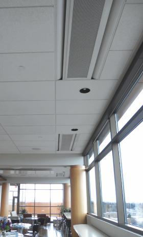
Figure 7-9b shows chilled beams installed flush within a suspended ceiling.
Chilled-beam systems operate in combination with an air-handling system that provides both ventilation air and controls the humidity of the air supplied to the active chilled beams. These air-handling systems vary in how they condition air supplied to the chilled beams. The goal is to reduce the humidity level to a point where the air volume supplied to the chilled beams is no more than 15% higher than the airflow rate required for ventilation.
Active chilled beams significantly reduce the size of ducting required in the building. In dry climates, the ducting is primarily sized for the peak ventilation airflow. In climates with higher humidity, the airflow rate is based on handling the latent load and is usually higher that the airflow required for ventilation. Reduced airflow means that smaller ducting can be used, as can lower power blowers. This can result in operating costs that are up to 50% lower than those of variable air volume (VAV) systems.
DEDICATED OUTDOOR AIR SYSTEMS (DOAS)
Chilled beams, as well as radiant cooling panels, are frequently combined with an air handling/dehumidification system called a DOAS, which stands for Dedicated Outdoor Air System.
DOAS systems use 100% outside air, rather than recirculating a portion of the air in the occupied space. During cooling operation, the objective of a DOAS air handler is to provide sufficient airflow to meet ventilation requirements AND to reduce the absolute humidity of that air to a condition that allows it to absorb the entire latent cooling load of the space. Because the very low-humidity air handles the full latent cooling load, devices such as chilled beams and radiant cooling panels can be operated at temperatures above the dewpoint of the room air and not experience surface condensation.
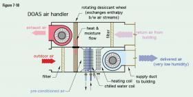
Figure 7-10 shows a typical DOAS air handler.
DOAS air handlers use a multi-row chilled-water coil to extract a high amount of moisture from the ventilation air. The highly dried air is then introduced to the occupied space in a manner that mixes it with the more humid air in the space, such as through an active chilled beam. This mixing allows the moisture being released into the space by occupants, activities or infiltration of humid outside air to be absorbed at a rate that doesn’t allow the relative humidity of that space to rise above an established threshold, such as a typical 50% RH.
Return air from the space is routed through an enthalpy wheel within the DOAS unit to recover some sensible and latent cooling effect before being exhausted outside.
During winter, a heating coil in the DOAS air handler can warm incoming ventilation air prior to introducing it into occupied spaced. The combination of chilled beams or radiant panels operating just above room dewpoint temperature, along with a DOAS system for ventilation and latent cooling, is highly efficient from the standpoint of distribution energy. This is largely based on shifting the majority of the sensible cooling load from “air-side” delivery using ducting to “water-side” delivery using a hydronic distribution system. With good design, the electrical power required for the hydronic portion of the system can be approximately 10% of the power required for an equivalent forced-air distribution system.
DOAS systems also allow the distribution ducting to be significantly smaller, and thus less expensive, compared to ducting that must handle the full sensible, latent and ventilation load. Smaller ducting can also reduce the height requirements for mechanical chases above suspended ceilings.
LATENT COOLING LOADS FOR CHILLED BEAMS & RADIANT PANELS
Since chilled beams and radiant panels are limited to sensible cooling, it is necessary to provide latent cooling (e.g., moisture removal from the air) by other means.
The following procedure can be used to determine the operating conditions of the radiant panel or chilled beam, and the DOAS air handler. It assumes a situation in which outside air at design cooling load conditions is drawn into the building to provide the required ventilation airflow.
Step 1: Establish the design values for dry-bulb and wet-bulb air temperature both inside and outside. Typical indoor design conditions are 75ºF and 50% relative humidity (which yields a wet-bulb temperature (e.g., dewpoint temperature) of 55ºF). Typical outdoor design conditions can be found in Chapter 14 of the 2017 ASHRAE Handbook of Fundamentals, or similar references.
Step 2: Using these design conditions, perform calculations to determine the sensible and latent cooling load of the space.
Step 3: Use a psychrometric chart (provided in Appendix B) to determine the absolute humidity for the indoor air (wi), as well as the outdoor air at design conditions. Absolute humidity is expressed as either pounds of water per pound of dry air or grains of water per pound of dry air. 7000 grains of water = 1 pound of water.
Step 4: Determine the outside airflow rate required for ventilation based on occupancy. Recommended ventilation airflow rates for different building types and activities can be found in the 2019 ASHRAE HVAC Applications Handbook. These rates can vary from 5 to 20 CFM per person. In general, the higher the metabolic activity level, and the higher the potential for undesirable pollutants to be generated within a space, the higher the recommended ventilation airflow rate per occupant.
Step 5: Determine the increase in absolute humidity (∆w) created by occupants or other processes within the room giving off moisture using Formula 7-2:
Formula 7-2:
$$ \Delta w = {q_L \over 4842(CFM)} $$
where:
$Δw$ = increase in absolute humidity caused by occupants (lb water/lb dry air)
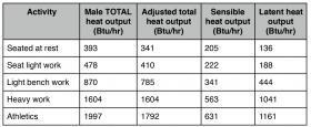
$q_L$ = latent load due to occupancy (Btu/hr)*
$CFM$ = required airflow rate of outside air (ft3/minute)
Step 6: Determine the increased absolute humidity when the room is occupied by adding the absolute humidity at the design indoor air conditions (i.e., 75ºF and 50% RH) to the increase in humidity caused
by occupants:
Formula 7-3:
$$ w_{max} = w_{di} + (\Delta w)_{occupants} $$
Where:
$w_{max}$ = absolute humidity of space based on design load conditions plus moisture added by occupants and activities (lb water/lb dry air)
$(\Delta w)_{occupants}$ = increase in absolute humidity caused by occupants or other moisture-generating processes (lb water/lb dry air)
$w_{di}$ = absolute humidity of indoor air at design conditions (lb water/lb dry air)
Step 7: Use a psychrometric chart (provided in Appendix B) to determine the elevated dewpoint temperature corresponding to this maximum absolute humidity. The minimum chilled water temperature supplied to the
chilled beams or radiant panels should be 3ºF above this elevated dewpoint temperature.
Step 8: Select a dry-bulb temperature at which the air handler will deliver cooled/dehumidified air to the space (Tdbc). Typical values range from 46ºF to 60ºF.
Step 9: Use Formula 7-4 to determine the portion of the sensible cooling load that is carried by the air handler.
Formula 7-4:
$$ q_{sah} = 1.08(CFM)(T_{dbo}-T_{dbi}) $$
Where:
$q_{sah}$ = sensible load carried by the air handler (Btu/hr)
$CFM$ = airflow rate through air handler
$T_{dbi}$ = dry-bulb temperature of air delivered to space (ºF)
$T_{dbo}$ = dry-bulb temperature of outdoor air at design conditions (ºF)
Step 10: The sensible cooling load that remains for the radiant panels is the total sensible cooling load minus the sensible load carried by the air handler.
Formula 7-5:
$$ q_{srad} = q_{stotal} - q_{sah} $$
Step 11: When radiant panel cooling is used, the sensible heat flux required of the panel is the total sensible load carried by the radiant panel divided by the area of the panel.
Step 12: Determine the required chilled water supply temperature to the chilled beam or radiant panel to provide the heat absorption rate calculated in Step 11. Refer to the manufacturer’s ratings of panel heat
absorption per unit of area versus chilled water supply temperature.
Step 13: Verify that the required chilled water supply temperature is at least 3ºF above the dewpoint temperature of the room when it is fully occupied. If it is not, consider shifting more of the sensible cooling load
to the air handler to reduce the required load on the chilled beams or radiant panel to a condition where it can safely operate above the maximum (occupied) dewpoint temperature of the room.
Step 14: The latent load that must be carried by the coil in the air handler is based on the change in air conditions across the coil and can be calculated using Formula 7-6.
Formula 7-6:
$$ q_L = 4842(CFM)\bigl(\Delta w\bigr) $$
Where:
$q_L$= latent load due to occupancy (Btu/hr)
$Δw$ = increase in absolute humidity caused by occupants or other moisture-generating processes (lb water/lb dry air)
$CFM$ = required airflow rate of outside air (ft3/minute)
The design goal in selecting the air handler is to produce relatively dry air (e.g., with a low dewpoint temperature) at a flow rate that satisfies the ventilation requirement of the space. When introduced into the space for ventilation, this dry air will absorb moisture at a rate that satisfies the latent cooling load and maintains a reasonable relative humidity within the space.
PIPING FOR DECOUPLED SENSIBLE & LATENT LOADS
Systems using chilled beams or radiant panels require piping and controls that can maintain the chilled water temperature to the chilled beams or radiant panels a minimum of 3ºF above the dewpoint temperature of the room. The 3ºF margin allows the chilled beams or radiant panels to absorb as much of the sensible cooling load as possible, while still providing a slight “safety factor” against formation of surface condensation due to sensor and controller accuracy tolerances.
These systems also require control of chilled water through the coil of a DOAS air handler so that ventilation air can be conditioned to a low dewpoint temperature, allowing it to absorb the full latent load of the space, as well as a portion of the sensible cooling load.
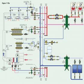
Figure 7-12a shows a concept system that uses a combination of chilled beams and radiant panels to supply the majority of sensible cooling, along with a DOAS air handler for the remainder of the sensible load and all of the latent load.
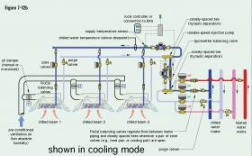
Figure 7-12b shows a closer view of the three chilled beams in Figure 7-12a.
The system in Figure 7-12a illustrates several possibilities. Fundamentally, it’s a “4-pipe” distribution system capable of simultaneous heating and cooling. It also shows a mix of radiant panels and chilled beams, either of which can operate in heating or cooling mode.
An array of three chilled beams operating in cooling mode is shown at the top of the schematic and in more detail in Figure 7-12b. These are active chilled beams that provide sensible cooling and also introduce ventilation air into their associated spaces. Water flow to each chilled beam is controlled by a zone valve. FlowCal™ balancing valves are used to automatically regulate the flow rate through each chilled beam when it is operating. Flow to the chilled beams is provided by a variable-speed pressure-regulated circulator operating in proportional differential pressure mode. The speed of this circulator automatically changes as the zone valves at each chilled beam open and close. The water temperature supplied to the chilled beams is regulated by another variable-speed “injection” pump.
The speed of this injection pump is regulated to maintain a set chilled water supply temperature to the chilled beams that is slightly above the current dewpoint temperature of the space. Flow from the chilled-water mains is allowed to pass through a pair of closely spaced tees when any of the chilled beams are active. This flow rate is regulated by FlowCal™ balancing valves. The closely-spaced tees provide hydraulic separation between the pressure across the chilled-water mains and the differential pressure of the injection circulator. Another set of closely-spaced tees separate the injection pump from the differential pressure of the variable-speed circulator supplying the chilled beams. The injection pump can also be controlled to regulate the supply water temperature to the chilled beams during heating mode. That temperature could be a setpoint or based on outdoor reset control.
Ventilation air that has been conditioned to a low dewpoint temperature is supplied from a DOAS air handler to each chilled beam and regulated by a motorized damper. The speed of the intake blower is regulated based on maintaining a set static pressure in the ducting system. The speed of the exhaust blower is regulated based on maintaining a set pressure differential between inside and outside air. Although not shown in Figure 7-12a, an enthalpy wheel could be added to the DOAS air handler to enable energy recovery from the building exhaust air stream.
The other cooling loads on the system are supplied by radiant panels. The upper radiant panel manifold can supply heating or cooling. The smaller radiant panel manifold only supplies cooling. The upper radiant panel manifold is separated from the heating and cooling mains by a hydraulic separator. A 3-way motorized mixing valve is used to keep the chilled water temperature to the radiant panel circuits slightly above dewpoint. This same mixing valve can be operated in heating mode based on outdoor reset control.
The DOAS air handler has a “deep” chilled-water coil capable of lowering the dewpoint of the ventilation air to a very dry condition. Flow through this coil is regulated by a variable-speed circulator operated by a controller that monitors the dewpoint of the air leaving the air handler. Flow through the heating coils is also regulated by a variable-speed circulator. Hydraulic separation of these injection circulators from the mains is provided by a hydraulic separator.
The chilled-water plant consists of two chillers, each with its own circulator. The chiller output is linked to the mains using a hydraulic separator. A duplex pair of variable-speed circulators creates flow in the chilled-water mains. The speed of the active circulator automatically varies as the zone valves that lead to the loads open and close.
Heated water is provided by a pair of modulating/condensing boilers. These boilers are also linked to the heated water mains through a hydraulic separator. . A duplex pair of variable-speed circulators creates flow in the heated water mains. The speed of the active circulator automatically varies as the zone valves that lead to the heating loads open and close.
There are many possible variations of this concept drawing. The key underlying concepts are:
• Separation of the sensible and latent cooling loads.
• Use of water-based heating and cooling conveyance to reduce air-side delivery to the ventilation requirements and a small portion of the sensible cooling load.
• Using chilled beams and/or radiant panels to absorb the majority of the sensible cooling load.
• Using a DOAS air handler with variable-speed blowers to supply chilled ventilation air at a low dewpoint temperature to absorb the latent cooling load. The same air handler can also heat incoming ventilation air during winter.
• Use of variable-speed pressure-regulated circulators with on/off flow control through branch circuits to reduce electrical energy consumption.
• Use of automatic flow-balancing valves to control flow rates in key areas of the system.
• Using a staged approach to chilled water production and heated water production.
• Using central hydraulic separators to isolate the pressure dynamics of the chiller and boiler plants from those of the distribution system.
• Using sets of closely-spaced tees or hydraulic separators to isolate the pressure dynamics established by the main distribution circulators from those established by the branch circulators.
• The option to use either 3-way motorized valves or variable-speed injection pumps to regulate heat transfer rates at coils.

