MANAGING PEAK DEMAND
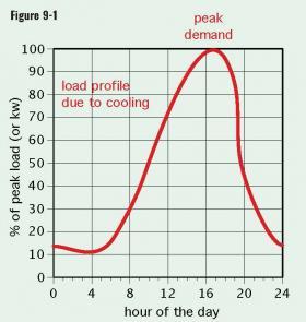
As the use of electrical-powered building cooling continues to expand, electric utilities face a challenge: how to supply the necessary electrical energy in ways that do not create increasingly sharp peaks in their power demand profile. For many utilities, especially those in warmer locations, peak power demand occurs in late afternoon on hot and humid days, as represented in Figure 9-1.
These peaks in demand necessitate preemptive operation of peak power-generating facilities, which often cost significantly more to operate per kilowatt•hour of delivered energy compared to base load generating facilities. Peaks that are largely created by motors also increase the reactive power loading on distribution grids, increasing transmission line losses.
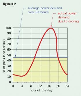
The area under the load profile curve in Figure 9-1 represents the total electrical energy (not power) supplied to the load over the 24 hour period. Figure 9-2 shows the average power that — if maintained for 24 hours — would result in the same total electrical energy supply.
For this specific load profile, the average power is only about 46% of the peak power.
An “ideal” scenario for an electric utility would be to provide the same total amount of electrical energy over the 24-hour period, but for the load profile shown in Figure 9-2, supply it at a constant power of 46% of the peak. This scenario is represented by the yellow area in Figure 9-2.
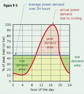
One way to conceptually achieve this “ideal” scenario would be to “clip off” the high-demand area shown in red in Figure 9-3 and use this area to “fill in” the low-demand areas shown in green in Figure 9-3.
One method that has been used to reduce peaks and shift more electrical power demand to periods of low demand is called “demand-side management.” In essence, electric utilities encourage customers to install equipment that can operate during low-demand periods and store energy until it’s needed. Financial incentives, such as time-of-use electrical rates and demand charges, is one of the key methods used for demand-side management. Time-of-use electrical rates offer electrical energy at significantly lower cost per kilowatt•hour when it is used during pre-defined periods of low demand. Those periods include nighttime hours, and in some cases weekends and holidays. Each utility offering these rates will have specific rate structures and times at which they apply.
One way to apply demand-side management to commercial cooling loads is through ice storage systems. Each pound of liquid water at 32ºF must give up 144 Btus to form one pound of ice at 32ºF. This allows ice to store much more cooling effect per pound of water compared to simply lowering the water’s temperature.
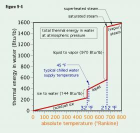
Figure 9-4 shows the total thermal energy in water versus its absolute temperature.
Notice the significant increase in energy as a pound of water changes from ice to water. This transition can also be viewed in reverse, as a large increase in “cold storage” as a pound of liquid water changes to a pound of ice. A pound of liquid water would have to change its temperature by 144ºF to store an equivalent amount of thermal energy.
Also notice that the change between ice and liquid water occurs at a constant temperature of 32ºF. This temperature is very close to the typical supply water temperature of 45ºF in chilled-water cooling systems.
The fundamental concept of an ice storage cooling system is to operate a chiller during periods of low utility rates (typically at night) to transform a volume of liquid water, held in one or more large, unpressurized, insulated containers, into ice. This ice is then melted to supply cooling during the subsequent peak loading period.
One possibility is a configuration called a “full storage” system. In this approach, the amount of ice created during a given “off-peak” period will be sufficient to meet the building’s entire cooling load during the subsequent “on-peak” period. In theory, this eliminates the need to operate the chiller during the “on-peak” period, and significantly lowers both the cost of operation and the peak power demand of the system. Most commercial buildings are billed for both the amount of electrical energy used over a billing period (e.g., kilowatt•hours), as well as the peak power demand (e.g., kilowatts) over any 15-minute period during that billing period.
Another scenario, referred to as a “partial storage” system is to displace the majority (but not all) of the on-peak cooling load using ice storage, and supply the balance of the load by operating the chiller. This approach typically has a higher operating cost relative to a full storage system, but also has a significantly lower installation cost since the chiller and ice bank storage can be smaller.
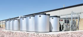
Figure 9-5 shows an array of large unpressurized insulated thermal storage tanks that serve as the “ice bank®.”
These tanks can range in volume from approximately 500 to 5000 gallons. They are available in a range of diameters and heights to coordinate with different installation locations and constraints. Multiple tanks can be combined in parallel to increase ice storage capacity.
Each tank contains several thousand feet of small diameter polyethylene tubing arranged in coils. The coils are immersed in water, which nearly fills the shell of the tank. The coils are also manifolded together, resulting in two 4-inch piping connections between the ice bank tank and the remainder of the system. Up to 9 tanks can also be connected in parallel using an internal header system.
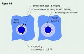
During the ice-making phase of operation, which typically lasts 8 to 10 hours, a propylene glycol or ethylene glycol antifreeze solution at approximately 25ºF is circulated through the tubing coils. An annulus of ice forms around the chilled tubing, as depicted in Figure 9-6.
The phase change from liquid water to ice creates a slight volumetric expansion within the tank. The water that is not yet frozen absorbs this expansion, resulting in a slight rise in water level within the tank. This approach prevents stresses within the tank. At the end of the ice-making phase, approximately 95%of the water in the tank has been converted to ice.
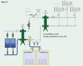
One or more of the ice storage tanks are combined with one or more chillers and a hydronic cooling distribution system. Figure 9-7 illustrate one possible arrangement, shown during the ice-making phase.
The chilled antifreeze solution exits the chillers at approximately 25ºF. A hydraulic separator prevents the pressure dynamics of the chiller circulators from interfering with the pressure dynamics of the main loop circulator and allows the chillers to maintain their minimum operating flow rate under other operating conditions. This separator also eliminates air, dirt and magnetic particles from the fluid.
The chilled antifreeze is routed into the coils of the ice storage tanks by a modulating valve. The slightly warmer antifreeze exiting the tanks flows through another hydraulic separator, through the main loop circulator, and eventually back to the chillers.
Although the loads are shown to be off during the ice-making cycle, which typically occurs at night, it is possible for one or more of the loads to operate during this time if needed. A 3-way motorized valve mixes some of the 31ºF antifreeze solution leaving the ice storage tanks and into the hydraulic separator, with some of the water returning from any active load to achieve a supply fluid temperature of approximately 44ºF to the active cooling load. The ice production cycle continues until approximately 95% of the water in the ice bank tanks has been frozen, or possibly until the off-peak period ends.
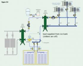
Figure 9-8 shows the system during the ice-melting mode. The chillers are assumed to be off, and the cooling load is completely supplied from the ice bank tanks.
If a condition is reached where the ice storage tanks can no longer supply the cooling load, one of the chillers would be operated, perhaps at partial capacity, to supplement the output of the ice storage tanks. The modulating 3-way valve would determine the proportions of flow through the ice bank versus straight through the valve.
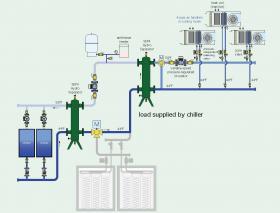
Figure 9-9 shows a scenario where the cooling effect available from the ice storage tank has been depleted (e.g., all ice melted and the water in the tanks elevated to a temperature that can no longer provide adequate cooling at the loads).
At this point, the chillers supply the entire cooling load. The two hydraulic separators allow the chiller flow rates to be independent of the main loop flow. They also allow the load flow rate to be independent of the main loop flow rate.
The load consists of multiple 4-pipe air handlers. Flow to each chilled-water coil is controlled by a zone valve. A pressure-independent balancing valve maintains a stable predetermined flow rate through each coil when the associated zone valve is open, regardless of the on/off status of the other air handlers. A variable-speed pressure-regulated circulator automatically adjusts its speed based on proportional differential pressure control. The 3-way mixing valve downstream of the load circulator would have its bypass fully closed. System fluid would be supplied to each air handler at 44ºF. The fluid leaving each active air handler at approximately 58ºF would pass through the hydraulic separator and back to the chiller. If modern ECM circulators are used, a building automation system can be used to match flow rate of the main loop circulator to the flow rate of the load circulator. This prevents mixing within the hydraulic separator and assures that the warmest fluid is returned to the chiller.
Ice-based thermal storage can be retrofitted to existing chilled-water distribution systems. In these situations, it is possible to install a generously sized (e.g., low approach temperature difference) plate & frame heat exchanger to separate the antifreeze solution in the thermal storage portion of the system from the water in the existing portion of the system.
Ice-based thermal storage cooling systems provide several benefits, including:
• Lower operating cost based on off-peak electrical rates.
• Reduced capacity chiller sizing relative to peak load (66% of peak load is a starting point estimate).
• Reduced utility demand charges due to reduced chiller capacity.
• Ability to provide several hours of cooling if the chiller is temporarily offline for maintenance following a full ice-making cycle.
• Ability to provide some cooling capacity during a power outage, assuming a sufficient backup generator is available to power the circulators.
• Some utilities offer incentives to reduce the installation cost of this type of system.
SUMMARY
Today, there are very few new or remodeled commercial buildings or institutional buildings that do not have a means of cooling. Its appeal, and availability in many different forms, make it an expectation rather than a luxury. As population patterns within the U.S. have progressively shifted to warmer climates, the market for cooling in nearly all commercial and institutional buildings has created continuously expanding market opportunities. This issue of idronics has discussed the unique and unmatched role that modern hydronics technology can play in supplying that market.
The following points summarize the design considerations for these systems:
• The starting point for all cooling system design is an accurate estimate of sensible and latent cooling loads.
• Piping for conveyance of chilled water is much smaller than ducting of equivalent cooling capacity.
• Hydronic-based cooling systems have much higher distribution efficiency compared to air-based cooling distribution systems.
• All terminal units that provide latent cooling must have drip pans.
• All chilled-water piping must be insulated and vapor- sealed to prevent condensation.
• Multiple staged chillers or heat pumps can provide commercial cooling capacity in locations that only have single phase power.
• Heat recovery chillers can serve simultaneous heating and cooling loads. So can water loop heat pump systems.
• Circulator power should be minimized, since it all adds to the cooling load. Use of variable-speed circulators in combination with valve-based zoning will significantly lower operating costs in multi-zone systems.
• Radiant cooling panels and chilled beams must remain above the current dewpoint temperature of the room to avoid condensation.
• Ice storage cooling systems can significantly lower operating cost and reduce the size of required chiller plants.

