Preface
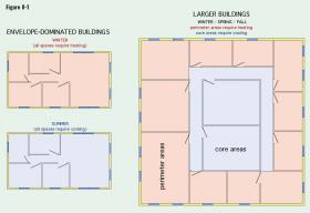
Many commercial and industrial buildings have heating and cooling load characteristics that are very different from smaller buildings. One of those characteristics is a frequent need for simultaneous heating and cooling in different parts of the building. On many days during fall and spring, the perimeter areas of commercial buildings may require heating, while the building’s core areas (e.g., those without exposed surfaces) require cooling, as depicted in Figure 8-1.
Although it’s possible to operate two separate systems — one for heating and the other for cooling — and use devices such as zoning dampers or zone valves to direct the heating or cooling where needed, this is not the most efficient approach. The heating system would be burning fuel or consuming electricity to create heat for the perimeter areas. The cooling system would be consuming electricity to absorb heat (e.g., create cooling effect). Neither system is attempting to move heat from where it’s present in access to where it’s needed in the building.
Buildings with simultaneous heating and cooling loads are well-suited to a water loop heat pump system, which can move heat from core areas to perimeter areas.
Water loop heat pump systems consist of several water-to-air heat pumps. Each heat pump has a refrigerant-reversing valve, allowing it to operate in either heating or cooling mode. All the heat pumps are connected to a common hydronic distribution system. Heat pumps operating in heating mode extract heat from the water circulating in the hydronic distribution system. Heat pumps operating in cooling mode dissipate heat into this hydronic distribution system. This allows excess heat in the building’s core areas to be moved to where it’s needed in the perimeter areas. Heat that is moved is heat that doesn’t have to be created.
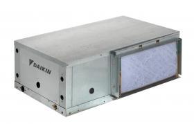
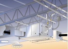
Figure 8-2 shows an example of a typical water-to-air heat pump that would be used in this type of system. Heat pumps with horizontal orientation are typically installed above suspended ceilings in commercial buildings. Those with vertical orientation are usually installed in mechanical rooms or mechanical closets. These heat pumps are
available in nominal cooling capacities ranging from 0.5 to 5.0 tons (6,000 to 60,000 Btu/hr).
An ideal situation for a water loop heat pump would allow all the heat collected from areas of the building requiring cooling to be moved to areas requiring heating. Under such conditions, and depending on the water temperature in the common water “loop” piping, the building would be heated and cooled at a fraction of what it would otherwise cost using an electric resistance heating system and a separate electrically powered cooling system.
This ideal situation would be when the building’s total heating requirement is equal to the building’s total cooling requirement plus the total electrical energy to run all the heat pumps, as expressed in Formula 8-1. Under these conditions, the water temperature in the piping loop would remain constant.
Formula 8-1:
$$ Q_{heating} = Q_{cooling} + P_{electrical} $$
Where:
$Q_{heating}$ = total heating requirement of the building (Btu/hr)
$Q_{cooling}$ = total concurrent cooling load of building (Btu/hr)
$P_{electrical}$ = total electrical power supplied to all operating heat pumps (Btu/hr) (kw x 3413)
Although these balanced load conditions are possible, they will not occur during winter or summer. During winter, it’s possible, even likely, that the building’s heating load will be significantly higher than its cooling load. Likewise, during summer, the entire building is likely to require cooling.
These situations create the need for supplemental heat input, and the ability to dissipate the heat of rejection from all the heat pumps running simultaneously in cooling mode.
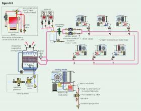
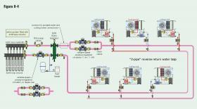
The most common way to add supplemental heat to the water loop is using one or more boilers. A typical way to dissipate heat that’s in excess of the building’s needs is by including a cooling tower in the system. These supplemental heating and cooling devices, along with several heat pumps, are shown connected to a common “2-pipe” reverse return piping loop in Figure 8-3.
A typical control criterion for a water loop heat pump system is to allow the loop temperature to “float” between 70ºF and 90ºF whenever possible, based on the rates of heat input and extraction from all operating heat pumps. The thermal mass of the water in the loop provides some buffering effect. If the heat input to the loop forces the water temperature above 90ºF, flow is directed through the cooling tower. If the loop temperature drops below 70ºF on a cold winter day, one or more boilers are operated. The working temperature of the loop makes it an ideal application for modulating/condensing gas-fired boilers. If conventional boilers are used in this type of system, they should be installed with anti-condensation mixing valves, as shown in Figure 8-3.
The operating temperature range of 70ºF to 90ºF is close enough to typical conditioned space temperatures that the water loop is usually not insulated and not subject to condensation.
Each heat pump branch contains a zone valve with a high Cv rating, or a motorized ball valve, that opens when the heat pump is operating. Each branch also contains a FlowCal™ balancing valve that automatically maintains a set flow rate through the heat pump when it operates. Most heat pump manufacturers specify flow rates of 2 to 3 gallons per minute per ton of heat pump heating capacity. Reinforced hoses are used to reduce vibration transfer between the heat pump and rigid piping. Each heat pump branch is also equipped with isolation and purging valves. These allow any heat pump to be isolated from the distribution loop and removed for servicing if necessary, without affecting operation of the other heat pumps.
Flow through the building loop is typically maintained 24/7. It’s provided by a duplex set of variable-speed pressure-regulated circulators that automatically adjust flow rate based on proportional differential pressure control. As more heat pumps turn on, flow in the loop is automatically increased, and vice versa. Only one of the two circulators operates at a time. The other serves as a backup. A controller automatically determines which circulator is operating and attempts to creates approximately equal elapsed run time for each circulator.
A DiscalDirtMag® separator provides high-efficiency air, dirt and magnetic particle separation for the system.
Some water loop heat pump systems use closed-loop cooling towers. The same fluid that passes through the water loop also passes through closed piping paths within the cooling tower. There is no contact between this water and the sump water used to enhance the tower’s evaporative heat dissipation. This is the type of cooling tower shown in Figure 8-3.
If the building loop system operates with all water, the cooling tower must be protected from freezing in winter. In some systems, the tower is isolated from the balance of the system and drained during winter. In other systems, a small flow of water from the loop is maintained through the tower to keep it from freezing. The modulating 3-way motorized valve shown in Figure 8-3 can provide this flow. The latter approach allows the tower to come online quickly during an abnormally warm day in winter.
Other systems use open cooling towers. In these systems, the tower is typically separated from the closed/pressurized building water loop by a plate & frame heat exchanger. That heat exchanger should be sized for a small approach temperature difference in the range of 2 to 4ºF. This helps keep the loop temperature down during cooling mode operation on hot summer days, and thus minimizes the drop in heat pump cooling performance.
In most systems, the cooling tower is located outside the building. However, it is possible to use a cooling tower mounted inside the building. Outside air enters the tower through a large louvered panel in an exterior wall. After passing through the tower, this air is discharged back outside through another larger louvered panel. When this type of tower is used, the discharge air should be directed away from nearby windows, doors, parked vehicles or areas of outdoor gatherings. This prevents water droplets in the discharge air, or residual water treatment chemicals in the sump water, from being discharged where they could cause adverse effects.
GEOTHERMAL WATER LOOP HEAT PUMP SYSTEMS
Water loop heat pump systems can also be adapted to geothermal earth loops. In some systems, the earth loop is sized to eliminate the need for a cooling tower and auxiliary boiler. In other systems, the earth loop may be sized to minimize the size of the cooling tower and boiler. Figure 8-4 shows an example of a system where the boiler and cooling tower have been eliminated.
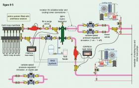
The earth loop portion of this system is interfaced to the building loop using a SEP4™ hydraulic separator. This component provides high-efficiency air, dirt and magnetic particle separation. It also provides hydraulic separation between the earth loop circulator and the building loop circulator. The hydraulic separation also allows the potential for the speed of the earth loop circulator to be regulated independently of the building loop circulator. For example, the speed of the earth loop circulator could be ramped up and down depending on the thermal load of the building. If there is a near balance between the heating and cooling loads in the building, the earth loop circulator could be operated at a very low speed since there is very little need for additional heat input to, or heat dissipation from the building loop.
The earth loop circulator speed could be regulated based on the rate of heat transfer supplied from the earth loop compared to the measured load in the building loop. These two rates of heat transfer can be monitored by CONTECA heat meters and transferred to a building automation system that in turn regulates the speed of the earth loop circulator. The piping for this concept is shown in Figure 8-5.
Aside from the source of supplemental heat supply and dissipation, there are important differences between a water loop heat pump system supplied by an earth loop versus one configured around a cooling tower and supplemental boiler.
One is the water temperature in the building loop. Whereas a “boiler/tower” heat pump system typically maintains the loop temperature between 70 and 90ºF, a building loop supplied from a geothermal system will operate over a much wider temperature range. Depending on the earth loop design, the site location and the cooling load, the summer loop temperatures can be comparable to those achieved using a properly sized cooling tower. However, during winter, the earth loop temperatures could drop much lower than 70ºF, perhaps as low as 30ºF.
Modern water-to-air heat pumps intended for geothermal applications can operate across these wide temperature ranges. Still, if the minimum loop temperature is expected to approach freezing, the system should be operated with an antifreeze solution. All piping and piping components must also be insulated to prevent surface condensation when operating at fluid temperatures below the dewpoint of interior air.
Another possibility is to connect one or more water-to-water heat pumps to the building loop. These heat pumps could be used to heat domestic hot water, supply radiant panels in some areas of a building, or supply heated or chilled water for a process load.
When water-source heat pumps are used for heating and cooling, the ventilation air is typically provided by a dedicated outdoor air system (DOAS). . During warm months, the DOAS cools and dehumidifies entering outside air. This air can be introduced directly into spaces by a separate duct system, or it can be mixed into the supply air stream leaving each heat pump. During winter, the DOAS would pre-heat the incoming ventilation air.

