PREFACE
The refrigeration cycle is the basis of compression heat pumps. During this cycle, a chemical compound called the refrigerant circulates around a closed piping loop passing through all major components of the heat pump. These major components are named based on how they affect the refrigerant passing through them. They are as follows:
• Evaporator
• Compressor
• Condenser
• Thermal expansion valve (TXV)
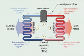
The basic arrangement of these components to form a complete refrigeration circuit are shown in Figure 2-1.
To describe how this cycle works, a quantity of refrigerant will be followed through the complete cycle.
The cycle begins at station (1) as cold liquid refrigerant within the evaporator. At this point, the refrigerant is colder than the source media (e.g., air or water) passing across the evaporator. Because of this temperature difference, heat moves from the higher-temperature source media into the lower-temperature refrigerant. As the refrigerant absorbs this heat, it changes from a liquid to a vapor (e.g., it evaporates). The vaporized refrigerant continues to absorb heat until it is slightly warmer than the temperature at which it evaporates. The additional heat required to raise the temperature of the refrigerant above its saturation temperature (e.g., where it vaporizes) is called superheat, which also comes from the source media.
This vaporized refrigerant then flows on to the compressor at station (2). Here a reciprocating piston or an orbiting scroll driven by an electric motor compresses the vaporized refrigerant. This causes a large increase in both pressure and temperature. The electrical energy used to operate the compressor is also converted to heat and added to the refrigerant. The temperature of the refrigerant gas leaving the compressor is usually in the range of 120º to 170ºF depending on the operating conditions.
The hot refrigerant gas then flows into the condenser at station (3). Here it transfers heat to a stream of water or air (e.g., the sink media) that carries the heat away to the load. As it gives up heat, the refrigerant changes from a high-pressure, high-temperature vapor into a high-pressure, somewhat cooler liquid (e.g., it condenses).
The high-pressure liquid refrigerant then flows through the thermal expansion valve at station (4), where its pressure is greatly reduced. The drop in pressure causes a corresponding drop in temperature, restoring the refrigerant to the same condition it was in when the cycle began. The refrigerant is now ready to repeat the cycle.
The refrigeration cycle remains in continuous operation whenever the compressor is running. This cycle is not unique to heat pumps. It is used in refrigerators, freezers, room air conditioners, dehumidifiers, water coolers, vending machines and other heat-moving machines.
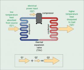
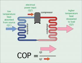
Figure 2-2 shows the three primary energy flows involved in the refrigeration cycle. The first energy input is low-temperature heat absorbed from the source media into the refrigerant at the evaporator. The second energy input is electrical energy flowing into the compressor whenever it is operating. The third energy flow is the heat output into the sink media at the condenser.
The first law of thermodynamics dictates that, under steady state conditions, the total energy input rate to the heat pump must equal the total energy output rate. Thus, the sum of the low-temperature heat absorption rate into the refrigerant at the evaporator, plus the rate of electrical energy input to the compressor, must equal the rate of energy dissipation from the refrigerant at the condenser. This is depicted by the arrows in Figure 2-2.
NON-REVERSIBLE VS. REVERSIBLE HEAT PUMPS
Heat pumps always move heat from a lower-temperature source media to a higher-temperature “sink” media. The basic non-reversible heat pump described in Figures 2-1 and 2-2 can be used as a dedicated heating device or a dedicated cooling device.
As a dedicated heating device, the evaporator side of the heat pump will always gather low-temperature heat from some source where that heat is freely available and abundant. The condenser side will always deliver higher-temperature heat to the load.
One example would be a heat pump that always delivers energy for space heating a building. Another would be a heat pump that always delivers energy to heat domestic water. Still another would be a heat pump that always delivers heat to a swimming pool.
As a dedicated cooling device, the evaporator side of a non-reversible heat pump always absorbs heat from a media that is intended to be cooled. Examples would be heat extraction from a building during warm weather, or heat extraction from water that will eventually be converted into ice. The condenser side of such a heat pump will always dissipate heat to some media that can absorb it (e.g., outside air, ground water or soil).
There are several applications where non-reversible heat pumps can be applied. However, one of the most unique benefits of modern heat pumps is that the refrigerant flow can be reversed to quickly convert the heat pump from a heating device to a cooling device. Such heat pumps are said to be “reversible.” A reversible heat pump that heats a building in cold weather can also cool that building during warm weather.
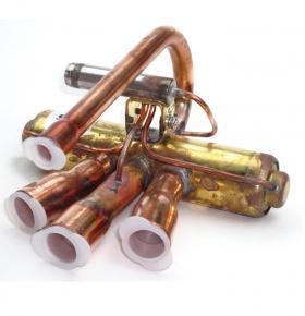
Reversible heat pumps contain an electrically operated device called a reversing valve. Figure 2-3 shows an example of a modern reversing valve.
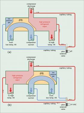
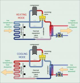
The type of reversing valve used in most heat pumps contains a slide mechanism that is moved by refrigerant pressure. The direction of movement is controlled by a small “pilot” solenoid valve. When the heat pump is in heating mode, the magnetic coil of pilot solenoid valve is not energized. This allows the high-pressure refrigerant leaving the compressor to position the slide within the reversing valve so hot refrigerant gas from the compressor goes to the condenser, as shown in Figure 2-4a.
When the heat pump needs to operate in cooling mode, the pilot solenoid valve is energized by a 24 VAC electrical signal. This allows the refrigerant pressure to immediately move the slide within the reversing valve to the opposite end of its chamber. Hot gas leaving the compressor is now routed to the heat pump’s other heat exchanger (e.g., what was the evaporator now becomes the condenser.) This is illustrated in Figure 2-4b.
Figure 2-5 shows where a reversing valve is installed in an air-to-water heat pump.
The reversing valve effectively “swaps” the functions of the heat pump’s two heat exchangers. The heat exchanger that serves as the evaporator in the heating mode serves as the condenser in the cooling mode. Similarly, the other heat exchanger that served as the condenser in the heating mode acts as the evaporator in the cooling mode.
The most common configuration for a reversible heat pump is one in which two thermal expansion valves are used in combination with two check valves. One thermal expansion valve functions during the heating mode, while the other functions during the cooling mode. Some heat pumps also use a single electronically controlled “bi-directional” thermal expansion valve. For simplicity, the heat pump refrigeration piping diagrams shown assume a single bi-directional thermal expansion valve.
HEATING MODE THERMAL PERFORMANCE
In the heating mode, there are two indices used to quantify heat pump performance:
a. Heating capacity
b. Coefficient of performance (COP)
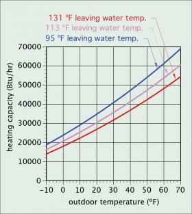
Heating capacity is the rate at which the heat pump delivers heat to the load. As such, it is similar to the heating capacity of a boiler. However, the heating capacity of any heat pump is very dependent on its operating conditions, specifically the temperature of the source media and the temperature of the sink media. The greater the temperature difference between the source media and the sink media, the lower the heat pump’s heating capacity. Figure 2-6 shows how heating capacity of a specific air-to-water heat pump varies as a function of outdoor air temperature and the water temperature leaving its condenser.
A heat pump’s heating capacity also depends on the flow rate of the source and sink media through the evaporator and condenser. The higher these flow rates are, the greater the heating capacity will be. This is the result of increased convection heat transfer at higher flow velocities. However, the gains in heating capacity are not proportional to the increase in flow rate. Heating capacity increases incrementally at high flow rates. In some cases, the gains in heating capacity do not justify the significantly higher electrical power input to larger circulators, higher speed operation of variable-speed circulators, or higher fan speeds. Water flow rates in the range of 2 to 3 gpm per 12,000 Btu/hr of rated heating capacity are generally recommended.
The coefficient of performance (COP) of a heat pump is a number that indicates the ratio of the beneficial heat output from the heat pump, divided by the electrical power input required to operate the heat pump. The higher the COP, the greater its rate of heat output per unit of electrical input power.
Formula 2-1 shows this relationship in mathematical form. The factor 3.413 in this ratio converts watts into Btu/hr. This makes COP a unitless number.
$$COP={{{heating\,output\,(Btu/hr)}}\over{{electrical\,input \,(watt)\,·\,3.413}}} $$
COP can also be visualized as the ratio of the heat output arrow divided by the electrical power input arrow, as shown in Figure 2-7.
Another way to think of COP is the number of units of heat output energy the heat pump delivers per unit of electrical input energy. Thus, if a heat pump operates at a COP of 4.1, it provides 4.1 units of heat output energy per equivalent unit of electrical input energy.
COP can also be considered as a way to compare the thermal advantage of a heat pump to that of an electric resistance heating device that provides the same heat output. For example, if an electric resistance space heater is 100% efficient, then by comparison, a heat pump with a COP of 4.1 would be 410% efficient. Some would argue that no heat source can have an efficiency greater than 100%. This is true for any heat source that simply converts a fuel into heat. However, much of the heat released by a heat pump is heat that was moved instead of created through combustion or direct conversion of electrical energy to heat. As such, its beneficial effect is equivalent to a heat source that would have an efficiency much higher than 100%.
The COP of all heat pumps is highly dependent on operating conditions. This includes the temperature of the source media, as well as the media to which the heat pump dissipates heat. The closer the temperature of the source media is to the temperature of the sink media, the higher the heat pump’s COP.
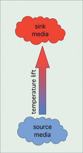
One can visualize the difference between the source and sink temperatures as the “temperature lift” the heat pump must provide, as shown in Figure 2-8.
The smaller the lift, the higher the heat pump’s COP.
The theoretical maximum COP for any heat pump was established by nineteenth century scientist Sadi Carnot and is appropriately called the Carnot COP. It is based on the absolute temperatures of the source media and sink media and is given in Formula 2-2.
$${COP_{Carnot}} = {{T_{sink}}\over {T_{sink} - {T_{source}}}} $$
COPCarnot = Carnot COP (the maximum possible COP of any heat pump)
Tsink = absolute temperature of the sink media to which heat is delivered (ºR)
Tsource = absolute temperature of the source media from which heat is extracted (ºR)
ºR = ºF + 458º
This Carnot COP is based on a hypothetical heat pump that has no mechanical energy losses due to friction or electrical losses due to resistance. It is also based on “infinitely sized” source and sink that remain at exactly the same temperatures as they give up and absorb heat. No real heat pump operates under such idealized conditions, and thus no real heat pump ever attains the Carnot COP.
The COPs of currently available heat pumps, even when operated under very favorable conditions, is substantially lower than the Carnot COP. Still, the Carnot COP serves as a way to compare the performance of evolving heat pump technology to a theoretical limit. It also demonstrates the inverse relationship between the “temperature lift” of a heat pump and COP.
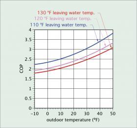
The COP of air-to-water heat pumps decreases as the outside air temperature decreases. It also decreases as the temperature of the water leaving the heat pump’s condenser increases. Figure 2-9 shows a typical relationship between COP versus outdoor temperature and the water temperature leaving the condenser for a modern “low ambient” air-to-water heat pump.
COOLING MODE THERMAL PERFORMANCE
In the cooling mode, the two indices used to quantify the performance of air-to-water heat pumps are:
a. Cooling capacity
b. Energy Efficiency Ratio (EER)
For air-to-air and water-to-air heat pumps, both of which use forced-air delivery systems, cooling capacity is divided into two parts: sensible cooling capacity and latent cooling capacity. Sensible cooling capacity is based on the temperature drop of the interior air stream passing through the heat pump’s evaporator coil. Latent cooling capacity is based on the ability of the interior coil to remove water vapor from the air stream. However, because air-to-water and water-to-water heat pumps both deliver a stream of cool water as their output, there is only one rating for cooling capacity, which in North American is usually expressed in Btu/hr.
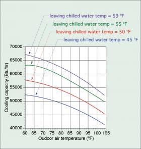
Cooling capacity is significantly influenced by the temperature of the air entering the heat pump’s condenser, and the temperature of water entering the heat pump’s evaporator. Cooling capacity increases when the temperature of the water delivering unwanted heat to the heat pump’s evaporator increases. Cooling capacity also increases when the temperature of the air absorbing heat from the heat pump’s condenser decreases. So, as was true for both heating capacity, and COP, the closer the source temperature is to the sink temperature, the higher the cooling capacity of the heat pump. This is shown, for a specific heat pump, in Figure 2-10.
ENERGY EFFICIENCY RATIO
In North America, the common way of expressing the instantaneous cooling efficiency of a heat pump is called Energy Efficiency Ratio (EER), which can be calculated using Formula 2-3.
$$EER={{Q_c}\over{w_e}}={{{cooling\,capacity(Btu/hr)}}\over{{electrical\,input \,wattage}}} $$
Where:
EER = Energy Efficiency Ratio
Qc= cooling capacity (Btu/hr)
We = electrical power input to heat pump (watts)
The higher the EER of a heat pump, the lower the electrical power required to produce a given rate of cooling.
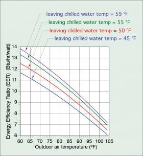
Like COP, the EER of an air-to-water heat pump depends on the source and sink temperature. The warmer the source media temperature is compared to the sink media temperature, the higher the heat pump’s EER. Figure 2-11 shows how the outdoor air temperature and leaving chilled-water temperature affect the EER of a specific air-to-water heat pump.
To maximize EER, designers of chilled-water cooling systems using either air-to-water or water-to-water heat pumps should use the highest possible chilled-water temperature that still allows adequate dehumidification. EER is also slightly influenced by flow rates. Higher flow rates of either the source media or the sink media produce small increases in EER. This is the result of increased convection on both the air-side and water-side heat exchangers.
WHAT DOES “TONS” MEAN?
In North America, the heating and cooling capacity of a heat pump is often stated in “tons.” In this context, a ton describes a rate of heat flow. More specifically, 1 ton equals 12,000 Btu/hr. Thus, a “4-ton” heat pump implies a nominal heating or cooling capacity of 4 x 12,000 or 48,000 Btu/hr. The tonnage of a heat pump has nothing to do with the heat pump’s weight. The unit of “ton” originated during the transition from stored natural ice as a means of cooling to mechanical refrigeration. It represents the average heat transfer rate associated with melting one ton of ice over a 24-hour period.
A description of a heat pump heating or cooling capacity based on tons is usually a nominal rating at some specific set of operating conditions. Thus, a “3-ton” rated heat pump could yield a heat output rate significantly higher than 3 tons when operated under more favorable conditions, and significantly less than 3 tons when operated under unfavorable conditions.
ENHANCED VAPOR INJECTION
One of the developments that has significantly improved the ability of air-source heat pumps to operate at low outside air temperature is called enhanced vapor injection (EVI). This refers to a modified refrigeration circuit that lowers the temperature of liquid refrigerant entering the outdoor evaporator when the heat pump is operating in heating mode. The lower the liquid refrigerant temperature entering the evaporator, the lower the air temperature at which the heat pump can operate. EVI also increases the refrigerant mass flow through the compressor, which helps in maintaining heating capacity at low outdoor air temperatures.
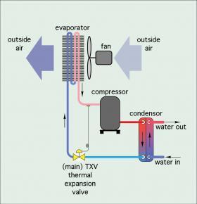
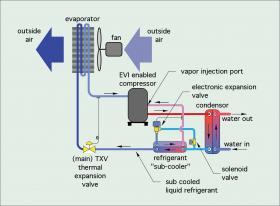
To understand EVI, it is helpful to consider a basic refrigeration circuit of a heating-only air-to-water heat system, as shown in Figure 2-12.
The temperature and liquid/vapor proportions of the refrigerant leaving the condenser, in part, determine the extent to which the thermal expansion valve can lower the refrigerant temperature entering the outdoor evaporator. This, in turn, limits the low ambient heating capacity and COP of the heat pump.
Figure 2-13 shows how the basic refrigeration circuit of Figure 2-12 is modified to allow EVI functionality.
EVI works by routing the refrigerant leaving the condenser through an intermediate heat exchanger called a “sub-cooler.” A portion of the refrigerant passes directly through one side of the sub-cooler. The other portion passes through an electronic expansion valve that lowers the refrigerant’s pressure and temperature prior to flowing through the other side of the sub-cooler. This portion of the refrigerant evaporates in the sub-cooler, absorbing heat from the other portion. This reduces the temperature of the liquid entering the thermal expansion valve, and thus, the temperature entering the evaporator. The lower the refrigerant temperature entering the evaporator, the better it can absorb heat from cold outside air.
The vapor formed as part of the refrigerant expands within the sub-cooler is at a pressure higher than that at the suction port of the compressor. This medium-pressure vapor is routed back into the refrigeration cycle using a specially designed scroll compressor with a medium-pressure vapor injection port. The medium-pressure refrigerant vapor enters at a specific location within the scroll set. That location prevents the injected vapor from flowing toward the low-pressure side of the scroll set. This effectively increases the compression ratio beyond the mechanical ability of the compressor alone.
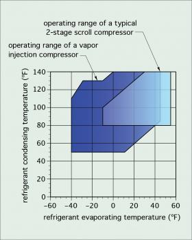
Figure 2-14 compares the refrigerant temperature operating range of a typical 2-stage scroll compressor versus a scroll compressor using EVI. Notice that the vapor-injected compressor can achieve much lower refrigerant evaporating temperatures. The lower the refrigerant evaporating temperature, the lower the outdoor air temperature from which useable heat can be extracted.
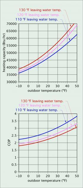
One characteristic of air-to-water heat pumps using EVI refrigeration systems is an increase in heating capacity as the temperature of the water leaving the condenser increases. This is shown in Figure 2-15.
This characteristic is counterintuitive because it is opposite from the decrease in heating capacity of non-EVI refrigeration systems as the water temperature leaving the condenser increases. However, as is true with non-EVI refrigeration circuits, there is a significant drop in COP as the water temperature leaving the condenser increases. Since the principal goal is to keep the heat pump’s COP as high as possible, it’s always best to operate the hydronic system at the lowest water temperature that maintains comfort in the heated space.
Many contemporary air-to-water heat pumps, especially those intended for use in cold climates, now use EVI refrigeration systems. These heat pumps are sometimes called “cold climate” or “low ambient” heat pumps to emphasize their suitability for use in cold locations. Many of these heat pumps are capable of operating with reasonable performance at sub 0ºF air temperatures.
DEFROSTING
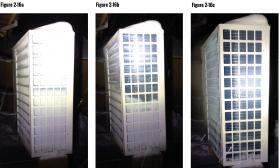
All air-source heat pumps (e.g., air-to-air and air-to-water) used in climates where outdoor temperatures drop below a nominal 50ºF will, at times, accumulate frost on the outdoor air-to-refrigerant heat exchanger, which operates as the evaporator during heating mode. The rate at which frost accumulates depends on several factors, such as relative humidity, concurrent precipitation and the evaporating temperature of the refrigerant. Figure 2-16a shows an example of a heavily frosted evaporator coil on a monobloc air-to-water heat pump.
Figure 2-16b shows this evaporator partially defrosted. Figure 2-16c shows the fully defrosted evaporator, with melt water draining from the bottom of the enclosure.
As frost builds on the evaporator, airflow is reduced, which reduces the ability of the refrigerant to absorb heat from outside air. To restore heating performance, it’s necessary to melt the frost off the evaporator. This is done automatically by temporarily switching the refrigerant flow direction using the reversing valve. This forces hot refrigerant gas through the evaporator, which rapidly melts the frost. In effect, the heat pump is temporarily switched to cooling mode operation while defrosting.
On most air-to-air heat pumps, the heat needed to melt frost comes from indoor air. This often results in cool air being discharged from the indoor portion of the heat pump. Although a typical defrost cycle may only last a few minutes, cool air discharging from the indoor portion of an air-to-air heat pump during cold weather is arguably a significant compromise in comfort.
However, most air-to-water heat pumps are connected to a buffer tank. Heat for defrosting comes from this tank. Even in systems without buffer tanks, the attached hydronic distribution system has much greater thermal mass relative to air, and thus, any deviation in the temperature of the distribution system during defrost is small and of short duration. In most systems, there is no detectable effect on indoor comfort. This is a significant advantage of air-to-water over air-to-air heat pumps.
Heat pump manufacturers offer different methods for defrosting. Sometimes defrosting occurs on a fixed elapsed time basis. It may also be “demand-controlled” defrost, which is usually based on low refrigerant pressure at the suction side of the compressor. Some modern air-to-water heat pumps also take the ambient air temperature into account when determining the need for defrosting. The goal is to clear the evaporator of frost with minimum required heat.
As the frost melts from the evaporator, water drops from and runs to the base of the heat pump. It is very important to ensure that this melt water doesn’t accumulate at the base of the heat pump. Accumulated melt water will eventually refreeze, and in doing so, can physically damage the evaporator, possibly even rupturing a refrigerant tube.
Most air-to-water heat pumps have a means of draining the melt water well away from the evaporator coil. Some use heated drip pans; others count on the water dripping several inches below the base of the heat pump. In cold climates, the outdoor portion of the heat pump should be mounted a few inches above expected snow depth to ensure that melt water can drain away from the unit. In cold climate applications, the outdoor portion of the heat pump should not be placed on a solid surface low to the ground.

