EXAMPLE #1: SINGLE ZONE "HEATING ONLY"
This and the related articles combines many of the details from previous sections into complete systems. These systems are configured around monobloc as well as split system air-to-water heat pumps. Some are “heating only” systems. Others include domestic water heating and chilled water cooling. Different approaches to details such as buffer tank piping, domestic water heating and auxiliary heat input are mixed into a variety of systems. Many additional combinations of these details and subassemblies are possible.
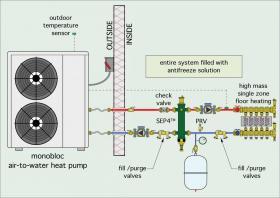
This system shown in Figure 8-1 is a single zone “heating only” application where a monobloc air-to-water heat pump supplies a heated floor slab. This simple arrangement would be ideal for a garage or shop environment.
The high thermal mass of the slab provides a substantial buffering effect, eliminating the need for a buffer tank. This system assumes that the heat pump can monitor the temperature of the fluid supplied to the floor heating manifold station. If the heat pump has a fixed-speed compressor, it would turn on and off to keep the supply water temperature within some differential above and below a target temperature. If the heat pump had a variable-speed compressor, it would modulate to keep the supply temperature as close to the target value as possible. The target temperature could be a fixed value, suitable to meet design heating load, or it could be based on outdoor reset control. The latter has a significant advantage because it allows the system to operate at lower fluid temperatures as the outdoor temperature increases. This would significantly improve the heat pump’s seasonal COP.
The power to operate circulators (P1) and (P2) is supplied through the heat pump. For the highest seasonal COP, both of these circulators should have electronically commutated motors (ECM).
A SEP4 hydraulic separator provides high-efficiency air, dirt and magnetic particle separation for the system. It also provides hydraulic separation between circulators (P1) and (P2), allowing for stable, but potentially different flow rates. This configuration also allows continuous operation
of circulator (P2), while circulator (P1) turns on and off with the heat pump. Continuous operation of the load circulator helps reduce variations in slab surface temperatures.
This system would operate with a solution of propylene glycol antifreeze. It is equipped with two bidirectional filling/purging valves to quickly fill the system and flush out bulk air during commissioning.
The spring check valve near the upper left connection on the SEP4 prevents reverse thermosiphoning through the heat pump when it is off.
The entire system can be operated from a simple wall thermostat.
EXAMPLE #2: EXTENSIVE ZONING "HEATING ONLY"
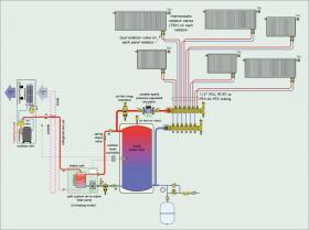
The system shown in Figure 8-2, is another “heating only” application, but with extensive zoning of the heating distribution system.
The split system air-to-water heat pump operates to keep the water temperature in the buffer tank at a temperature based on outdoor reset control. This water supplies a homerun distribution system in which a single manifold station supplies six independently controlled panel radiators, each equipped with a thermostatic valve operator. Each panel radiator is sized to provide design heat output to its associated space when supplied with water at 120ºF. As the outdoor temperature increases, the target temperature in the buffer tank decreases. This significantly increases the heat pump’s seasonal COP.
The buffer tank is piped in a 3-pipe configuration, which allows heat to flow directly from the heat pump to the heat emitters, as required, when the heat pump is operating. The balance of the flow leaving the heat pump passes through the buffer tank. All flow returning from the panel radiators passes into the lower portion of the tank. This helps ensure that the thermal mass of the tank is well “engaged” in the energy flow processes.
The heating distribution system is very simple. A single variable-speed pressure-regulated circulator operates continuously during the heating season. It’s speed automatically increases and decreases to maintain a constant differential pressure as the thermostatic valves on the panel radiators open, close or modulate.
The thermostatic valve at each radiator allows it to operate as a separate zone, maintaining the desired comfort level in each space. The split system heat pump allows the hydronic system to operate without need of antifreeze. A magnetic dirt separator protects the heat pump’s condenser. A combined air/dirt/magnetic particle separator protects the permanent magnet motor in the ECM circulator for iron oxide. It also provides high-efficiency air separation for the system.
A spring check valve prevents reverse thermosiphoning between the buffer tank and heat pump. This reduces extraneous heat loss through the piping when the heat pump is off. The heat pump can be isolated from the balance of the system for service if necessary. This system also has very simple control requirements. A single switch can be used to “enable” the system at the start of the heating season. The heat pump and its associated circulator turn on and off as necessary to maintain the target water temperature in the buffer tank. The distribution circulator (P2) operates continuously but is always tracking the differential pressure present based on the status of the thermostatic radiator valves. With current ECM circulator technology and proper component sizing, this distribution system could precisely deliver over 1,500 Btu/hr per watt of electrical energy supplied to circulator (P2). This is much higher distribution efficiency than what could be attained with forced-air delivery.
EXAMPLE #3: MULTIPLE ZONES HEATING WITH MULTIPLE HEAT EMITTERS
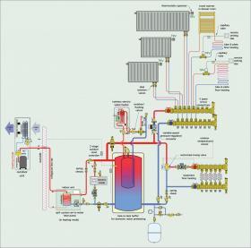
The system shown in Figure 8-3 supplies multiple zones of space heating with a mixture of heat emitters. It also provides domestic hot water.
A split system air-to-water heat pump is the primary heat source. An electric boiler, piped in parallel with the heat pump’s condenser, provides a second stage of heat input if needed. It also provides a backup to the heat pump should it be down for service. Each heat source is equipped with a pressure relief valve and can be fully isolated if necessary. Depending on local codes, the electric boiler may require a low water cutoff and a manual reset high limit controller.
Both heat sources supply a “tank-in-tank” buffer. The inner tank is constructed of stainless steel and holds 40 gallons of domestic water. It is surrounded by an outer tank that receives heat from the heat pump or the electric boiler. Heat flows from the system water in the outer tank to domestic water in the inner tank whenever the former is at a higher temperature than the latter. Domestic cold water enters the inner tank whenever there is a draw from a hot water fixture. The temperature of the domestic water leaving the inner tank depends on the temperature maintained in the tank shell. A thermostatically controlled tankless electric water heater boosts the domestic water to the desired supply temperature.
The buffer tank has a 3-pipe configuration. Heated water from the heat pump or electric boiler can flow directly to one or more of the space heating zones when either heat source is on at the same time as one or more of the zones.
Any difference in flow rates between the heat source(s) and zones passes through the buffer tank. All return flow passes into the lower portion of the buffer tank, and thus keeps its thermal mass well engaged. A spring-loaded check valve is installed in the piping leaving the heat pump and the electric boiler. These valves prevent reverse thermosiphon flow from the heated tank through either heat source when they are off.
The water temperature in the tank is controlled by a 2-stage outdoor reset controller. At design load conditions, the target water temperature in the tank is 120ºF. The target temperature decreases as the outdoor temperature increases. The minimum target temperature is 100ºF. Maintaining the tank temperature in this range allows the heat pump to operate with relatively good COPs. It also allows the heat pump to provide the majority of the “temperature lift” required for domestic hot water. If the heat pump is not able to maintain the necessary target temperature, the controller operates the electric boiler for supplemental heat input. There is a 5-minute interstage time delay to allow time for the heat pump to stabilize its operation before turning on the electric boiler.
Space heating is supplied through several types of heat emitters. The home’s main floor uses a combination of panel radiators, a towel warmer, and two areas of tube & plate underfloor heating. All of these emitters have been sized for design load output at 120ºF, and thus they can all be supplied as parallel circuits. The towel warmer is combined in series with a short tubing circuit that provides a small area of floor heating in the master bathroom. The three panel radiators each have integral thermostatic radiator valves and operate independently. The master bathroom and one other area of floor heating are equipped with non-electric modulating valves that are coupled to remote setting dials by capillary tubes.
Flow to all the main floor circuits is provided by a variable speed pressure-regulated circulator operating in constant differential pressure mode. All circuits begin and end at a common manifold station that is equipped with three “extra” connections. Those connections are initially capped but allow additional panel radiators or other emitters to be easily added in the future.
The home’s basement slab is also heated. The slab circuits require lower water temperature compared to the main floor circuits (100ºF water at design load). This water temperature is provided by a 3-way motorized mixing valve, also operated using outdoor reset control.
EXAMPLE #4: TWO-ZONES HEATING AND COOLING
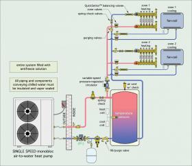
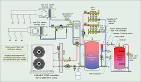
The system shown in Figure 8-4 provides heating and cooling to two zones. The system can only operate in one mode (e.g., heating or cooling) at a time. The buffer tank and heat pump are shown in heating mode.
The heating and cooling source is a single speed monobloc air-to-water heat pump. The buffer tank is piped in a 3-pipe configuration and is used in both heating and cooling modes. The entire system operates with a solution of propylene glycol antifreeze.
In heating mode, a variable-speed pressure-regulated circulator supplies two independent zones of radiant panel heating. Flow through each manifold station is controlled by a zone valve. Each manifold station also has a flow balancing valve. The zone valves to the fan-coils remain closed during heating mode.
In cooling mode, the same circulator supplies two independently controlled fan-coils. Each fan-coil circuit has a flow balancing valve. The zone valves to the heating manifold stations remain closed during cooling mode.
During heating mode, the heat pump and its associated circulator are turned on and off based on an outdoor reset controller that monitors the temperature at the mid-point of the buffer tank. This control action is independent of any call for heat from the room thermostats. The warmer the outdoor temperature, the lower the target temperature calculated by this controller. The maximum water temperature during heating mode is 110ºF. The minimum temperature is 80ºF.
The reset controller operates on a 10ºF differential centered on the target temperature. These temperatures allow the heat pump to operate at a relatively high COP. During cooling mode, the heat pump and its associated circulator are turned on and off based on a temperature setpoint controller that monitors another sensor at the midpoint of the tank. The heat pump is turned on when the tank temperature is 60ºF or higher. The heat pump is turned off when the tank temperature drops to 45ºF. The heat pump operates independently of calls for cooling from the room thermostats. Spring check valves are used to prevent reverse thermosiphoning from the tank, and to limit chilled water migration into the heating portions of the distribution system.
A magnetic dirt separator is used to protect the heat pump and high-efficiency circulator for dirt and iron oxides.
EXAMPLE #5: FLOOR HEATING CONTROLLED ZONES AND CHILLED WATER COOLING ZONES
The system shown in Figure 8-5 provides two independently controlled zones of floor heating, as well as two associated zones of chilled water cooling. It also provides domestic hot water.
This system is supplied by a variable-speed monobloc air-to-water heat pump. It’s variable speed capability allows the cooling portion of the system to operate without a buffer tank. In cooling mode, the speed of the heat pump’s compressor automatically adjusts as necessary to maintain a chilled water temperature between 45° and 60ºF when either (or both) of the chilled water air handlers is operating. Note: Zoned cooling distribution systems should not be used with a fixed-speed heat pump unless a buffer tank is provided.
A motorized diverter valve is used to route the heat pump’s output to the balance of the system associated with each mode of operation. It is possible for this system to deliver limited amounts of simultaneous heating and cooling. The buffer tank could deliver some amount of heating to the floor circuits as well as preheat domestic water while the heat pump is operating in cooling mode.
One possible control scenario would be to set up controls to prioritize cooling operation during the cooling season and heating mode operation during the heating season. The heat pump would switch to the lower priority load only after temporarily satisfying the higher priority load.
Another control possibility would be to set the target temperature of the buffer tank using outdoor reset control during the heating season, and switch that target temperature to a higher, narrower range during warm weather when the heat pump’s COP is relatively high. This would allow a higher percentage of the energy needed for domestic hot water to be supplied by the heat pump rather than the resistance heating elements in the supplemental water heater.
EXAMPLE #6: MULTIPLE AIR-TO-WATER HEAT PUMPS
It is possible to use multiple air-to-water heat pumps in systems that require more heating or cooling capacity than can be supplied by a single heat pump. The use of multiple heat pumps also adds “redundancy” to the system in the event that one of the heat pumps is down for service.
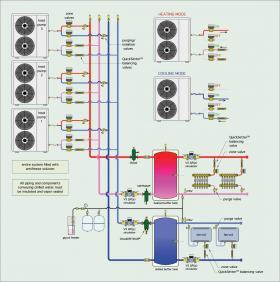
The system in Figure 8-6 shows three monobloc air-to-water heat pumps piped so that each heat pump can independently operate in heating or cooling mode.
This system has a “hot” buffer tank and a “cold” buffer tank. The system controls monitor the temperature of each tank and call for a heat pump to turn on when the temperature of either tank deviates slightly from its target temperature or outside of a set temperature range. The water temperature in the “hot” buffer tank would be regulated based on outdoor reset control. The water temperature for the “cold” buffer tank would be maintained between 45° and 60ºF whenever a cooling load is present. When a heat pump is called to operate, the zone valve pairs associated with its mode of operation open. The status of the heat pump’s reversing valve is also set. A variable-speed pressure-regulated circulator operates to create flow through the appropriate buffer tank. The speed of the circulator is based on proportional differential pressure control. The speed automatically increases or decreases depending on how many heat pumps are operating. The valving at each heat pump is also arranged so that the zone valves or heat pump can be isolated from the balance of the system if necessary for service.
Each buffer tank provides hydraulic separation between the heat pump circulators and the load circulators.
The heating zones are supplied by low-temperature radiant panels. Flow to each manifold station is controlled by a zone valve. Each manifold station piping assembly is also equipped with a balancing valve and purging valve. These valves are arranged so that each manifold station and its associated zone valve can be completely isolated from the balance of the system if necessary for service.
The cooling zones are supplied by fan-coils. Each fan-coil piping assembly is equipped with a balancing valve and purging valve. These valves are arranged so that each fan-coil and its associated zone valve could be completely isolated from the balance of the system if necessary for service.
Because this system can simultaneously supply heating and cooling, one mode of operation must take priority when staging the heat pumps. Several possibilities exist. For example, during heating season, the ability to maintain adequate water temperature in the “hot” buffer would be a likely priority. Once that temperature is established, at least one of the heat pumps would be allowed to operate in cooling mode, if a cooling load is present. During the cooling season, it’s likely that all heat pumps would be prioritized to satisfy the cooling load.
Although not shown in Figure 8-6, it would be possible to operate a water-to-water heat pump between the two buffer tanks when a simultaneous demand for heating and cooling exists. The air-to-water heat pumps would supplement the rate of heating or cooling needed by the system.
The piping and control concepts discussed for this system could be extended to additional numbers of heat pumps if needed. The “hot” buffer could be used to supply a mix of heat emitters, such as radiant panels and panel radiators. Likewise, the “cold” buffer could supply a mix of terminal units such as fan-coils, air handlers and radiant cooling panels. The latter requires special piping and controls to ensure that the panel always remains above the dewpoint of the interior air.
More information on radiant cooling is available in idronics #13
SUMMARY OF SYSTEMS EXAMPLES
21st century refrigeration techniques now make it possible for air-source heat pumps to operate in cold winter climates, with significantly improved performance compared to earlier-generation heat pumps. By combining low-ambient air-source heat pump technology with the versatility and high distribution efficiency of modern hydronics, designers can create systems for unsurpassed heating and cooling comfort, as well as domestic hot water production. Those systems are ideally suited for use with renewably sourced electricity, carbon reduction goals and “net zero” building projects. When properly selected and applied, low-ambient air-to-water heat pumps can approach the performance of geothermal heat pump systems at significantly lower installation cost and complexity. Air-to-water heat pump systems offer hydronic heating professionals a means of responding to evolving market trends and constraints without compromising quality, comfort or efficiency.

