Mounting outdoor heat pumps
Most air-to-water heat pumps have outdoor units that serves as the evaporator in heating mode and condenser in cooling mode. Although outdoor units are made and tested to withstand relatively harsh environments, thoughtful mounting will extend their service life and help ensure good performance.
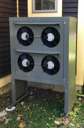
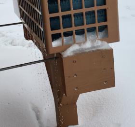
Outdoor units should be mounted above the deepest expected snow level. This allows for adequate airflow regardless of weather. Elevating the unit at least one foot above the ground also reduces accumulation of grass clippings and leaves. Figure 7-1 shows the outdoor unit of a split system mounted on a stand that keeps it at about two feet above the ground in a location that experiences
deep snow.
This stand is bolted to four 6-inch diameter concrete piers that provide stability.
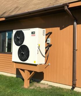
Outdoor units should be mounted in locations where runoff from roofs will not fall on them. If mounted under an eve, a gutter should be installed to catch roof runoff and route it away from the outdoor unit, as shown in Figure 7-2. Also keep the unit away from locations where icicles could form above the unit.
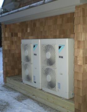
In some situations, it may be possible to mount the outdoor unit under a roof or wide overhang. Always verify that there is adequate space behind the unit for proper airflow. Manufacturers typically specify a minimum distance from the rear of the unit to a wall. Figure 7-3 shows an installation where two outdoor units are mounted under a wide overhang, and on a base that elevates them well above ground level.
In heating-dominated climates, and when other factors can be accommodated, it’s preferable to mount the outdoor unit at the southside side of the building where solar radiation can create a “microclimate” that slightly warms the surrounding air.
Always consider that any outdoor unit will emit some sound when operating. Units with inverter compressors and variable-speed fans tend to produce less sound than those with fixed-speed compressors. Still, avoid mounting locations near outdoor patios, decks or bedroom windows.
The length of the refrigeration line set should be factored into the decision on mounting location. In general, the shorter the line set, the better the heat pump’s heating and cooling performance. Manufacturers typically charge the outdoor unit with sufficient refrigerant to accommodate a specified length of line set. Length allowances of 15 to 30 feet are common. If the line set has to be longer, additional refrigerant must be added to the system when it is commissioned.
Although there are instances where condenser units for air-conditioning systems have been mounted on low concrete slabs or plastic pedestals, this is not recommended for air-to-water heat pumps, especially in cold northern climates. Mounting the outdoor unit near ground level tends to increase debris accumulation on the coil and make the unit more ulnerable to insects, rodents and animal urine. Snow accumulation can interfere with air flow through the evaporator coil and fans. Melt water from defrosting can also accumulate and refreeze on slabs, possibly damaging the unit.
Once the outdoor unit of a split system is connected to the refrigeration piping, it is good practice to close off any gaps where this piping joins the outdoor cabinet. Gaps at this location provide an entry point for mice, which can chew on wiring and insulation, build nests or otherwise degrade internal components.
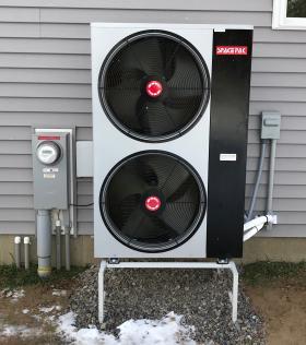
Figure 7-6 shows an outdoor unit mounted on a simple commercially available steel stand that elevates it above the ground.
The legs of this stand are bolted to pressure-treated 2x6 boards that are leveled and placed slightly below finish grade. The area under the unit was then covered with a landscaping fabric to prevent weed growth. Crushed stone was placed over the landscape fabric to keep it in place. All fasteners are stainless steel.
The national electric code requires a service disconnect adjacent to every outdoor heat pump or air-conditioning condenser. It should be mounted close to, but not behind the unit, as seen in Figure 7-6.
Most outdoor units are supplied with vibration-dampening mounting studs, which incorporate a layer of stiff rubber between the base of the unit and its mounting frame.
If the unit will be mounted in a high wind area, it is preferable to orient it so that prevailing winds don’t directly impinge on the front face where airflow from the fans is released. It’s also advisable to secure the mounting frame to the building foundation so that the unit is not excessively buffeted by high wind gusts.
Piping connections
All monobloc style air-to-water heat pumps require two piping connections to the balance of the system. There will be some slight movement in the outdoor unit due to temperature changes, wind buffeting and even the potential that someone accidentally “bumps” into the unit. Outdoor units that house a compressor also generate some vibration. Given these issues, it’s advisable to provide some flexibility and vibration-absorbing capacity between the outdoor unit and the piping it connects to inside the build.
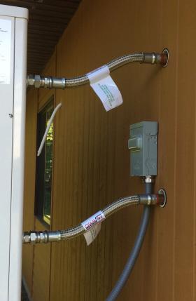
One approach is to use reinforced flexible piping connectors, as shown in Figure 7-7.
These 1-inch pipe size flexible connectors have a swivel fitting at one end, allowing for fully tightened connections without stressing the connector. They have 1-inch MPT threads that connect to the heat pump and the rigid copper tubing at the wall. Note the slight offset of the connections, which minimizes stress when the outdoor unit moves slightly.
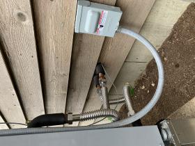
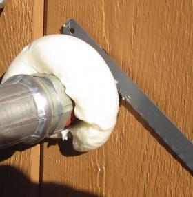
Another option is to connect the heat pump to piping at the wall using corrugated stainless steel tube (CSST) assemblies, as shown in Figure 7-8.
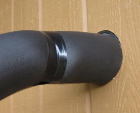
Piping penetrations in exterior walls should be done in ways that prevent entry of precipitation or insects. They should also prevent any condensation that occurs during cooling mode operation from leaking into the wall cavity.
After all piping connections have been pressure-tested to ensure there are no leaks, all outdoor piping should be wrapped with a suitable insulation. The outside surface of the insulation should be protected against ultraviolet degradation using a UV-resistant tape or coating. This has not yet been done in Figure 7-11.
Buffer tanks
Anytime an on/off heat source is combined with a zoned hydronic distribution system, there is potential for short cycling of that heat source. That potential can be reduced by using a buffer tank in the system. An example would be a 4-ton on/off air-to-water heat pump supplying several individually controlled panel radiators. Each radiator represents a “micro-zone.” The output of such a zone might only be 5 to 10% of the heating capacity of the heat pump. If several micro-zones are connected to a header that leads directly to the heat pump, even a heat pump that can modulate down to perhaps 30% of rated capacity, short cycling is very likely.
Beyond this primary function, buffer tanks can also provide hydraulic separation between simultaneously operating circulators and an energy reserve for domestic water heating.
The size of a buffer tank is based on two considerations:
- What is the minimum run time of the heat pump that avoids their definition of “short cycle?”
- What is the allowed temperature change of the buffer tank during the minimum on-cycle time?
Once values for these two parameters are chosen, the minimum size of a buffer tank can be determined using
Formula 7-1:
$$V = {{t\,(Q\,_{heat source}\,-q\,_{load})} \over 500\,(\Delta T)}$$
where:
V = required volume of the buffer tank (gallons)
t = desired duration of the heat source’s “on-cycle” (minutes)
Qheat pump = maximum expected heat output rate of the heat pump (Btu/hr)
qload = rate of heat extraction from the tank (can be zero) (Btu/hr)
∆T = temperature rise of the tank from when the heat source is turned on to when it is turned off (ºF)
Here’s an example. An air-to-water heat pump with a maximum expected heat output of 48,000 Btu/hr is to operate with a minimum on-cycle of 10 minutes while supplying a towel warmer radiator releasing heat at 2,000 Btu/hr. The heat pump responds to the buffer tank temperature. It turns on when the buffer tank temperature drops to 100ºF, and off when the tank reaches 120ºF. What is the necessary buffer tank volume to achieve this performance?
Solution: Just put the values into Formula 7-1 and run the calculation.
$$V = {{t\,(Q\,_{heat source}\,-q\,_{load})} \over 500\,(\Delta T))}= 10 \,{{(48000\,-\,2000)}\over500\,(120-100) }=46\,gallons$$
Larger buffer tanks can provide longer heat source oncycles. They can also allow a narrower temperature change over a specific on-cycle. It’s easy to evaluate the trade-offs between on-cycle length and tank temperature swing using Formula 7-1. Larger buffer tanks obviously cost more, take up more room in a mechanical room and usually have higher standby heat loss.
In systems where the buffer tank will contain chilled water for cooling, it is essential that all piping connections are insulated and vapor sealed. This is especially true for metal tanks. If moist room air comes in contact with cold piping, fittings or the pressure vessel, condensation will form and quickly cause staining or superficial corrosion.
Buffer tank piping
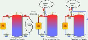
There are several ways to pipe buffer tanks. They are called “4-pipe”, “3-pipe” and “2-pipe” configurations. All three configurations are shown in Figure 7-12.
The 4-pipe configuration is the “classic” way to pipe buffer tanks in hydronic systems. The heat source adds heat on one side, while the load removes heat from the other side. This piping configuration provides excellent hydraulic separation between the heat source circulator and the load circulator(s).
One characteristic of a 4-pipe configuration is that all heat from the heat source must pass through the tank on its way to the load. This isn’t necessarily a problem when the buffer tank temperature is being maintained by the heat source, independently of calls from the load. However, this arrangement retards heat transfer from the heat source to the load if the tank is allowed to cool substantially.
A check valve should be installed on the heat pump side of the buffer tank to prevent reverse thermosiphoning through the heat pump when it is off.
The 2-pipe configuration places the load between the buffer and the heat pump. This allows the possibility of passing heat directly from the heat source to the load without that heat having to first pass through the buffer tank. This enables faster recovery from setback conditions.
One limitation of the 2-pipe configuration is that a differential pressure valve that creates a forward opening resistance of 1 to 1.5 psi, or a motorized ball valve, needs to be installed in the heat pump piping to prevent a portion of the flow returning from the load from passing through the heat pump when it’s off. It’s also necessary to keep the tees that connect to the load as close as possible to the tank to allow for good hydraulic separation.
Two-pipe buffers should only be used when the heat source is turned on and off based on buffer tank temperature.
The reasoning is as follows: if the heat pump flow rate and load flow rate are similar, there will be very little flow through the tank. This could cause the heat pump to shut off based on satisfying the space heating thermostat, without adding much heat to the tank. In this scenario, the tank is not well “engaged” in the heat flow process. However, when the heat pump is controlled directly from tank temperature, the heat pump should continue to run even after the space heating thermostat is satisfied, storing heat that’s immediately ready to flow to the next zone requesting it.
The 3-pipe buffer tank configuration is an excellent compromise between the strengths and limitations of the 4-pipe and 2-pipe configurations. It provides a way to pass heat directly from the heat pump to the load when both are operating. It also forces flow returning from the load through the lower portion of the tank, and thus, ensures that the tank’s thermal mass is engaged. This “direct-to-load” configuration has been modeled using TRNSYS simulation software and found to increase the seasonal COP of the heat pump by keeping the lower portion of the tank slightly cooler than is possible with other piping configurations.
Buffer tanks connected to heat pumps tend to have minimal temperature stratification. This happens because most heat pumps have recommended flow rates of 3 gpm per ton (12,000 Btu/hr) of capacity. A typical 4-ton air-to-water heat pump operating at these conditions would “turn over” an 80-gallon buffer in less than 7 minutes. Those flow rates, especially if introduced vertically into the tank, create lots of internal mixing.
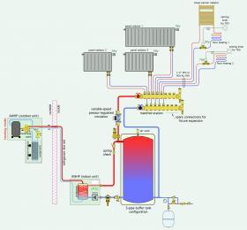
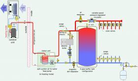
Figure 7-13 shows an example of an air-to-water heat pump supplying a highly zoned distribution system through a buffer tank with a 3-pipe configuration.
The split system air-to-water heat pump supplies a combination of low-temperature panel radiators and radiant floor panel circuits. The heat output of each radiator and radiant panel circuit is regulated by a nonelectric thermostatic valve. A variable-speed pressureregulated circulator automatically adjusts speed based on the status of these valves. The heat pump is turned on an off to maintain the water temperature at the middle of the buffer tank between 100 and 110ºF. In addition to buffering the heat pump against short cycling, the tank provides hydraulic separation between the heat pump’s internal circulator (P1) and the variable-speed distribution circulator (P2).
Dirt separation
The refrigerant-to-water heat exchangers used in modern air-to-water heat pumps often have narrow flow passages. It is essential that the fluid passing through these heat exchangers is clean. A low-velocity zone dirt separator, as shown in Figure 7-13, is one solution. If the system has one or more ECM-based circulators, a magnetic dirt separator is recommended.
Auxiliary heating provisions
Although it’s possible to size an air-to-water heat pump such that it can supply design heating load, or even for that load plus a safety factor, such sizing is not always economically justified. The Boston house example described in section 5 demonstrated that a low-ambient air-to-water heat pump having a balance point capacity of about 65% of the design load could supply about 96% of the total seasonal heating energy. The nominal 4-ton heat pump would have to be increased to a nominal 6-ton unit to meet the design load. Under typical partial load conditions, the larger heat pump would be more subject to short cycling. The suggested solution was to install an electric boiler that could provide supplemental heat during the few hours in a typical year when it was needed, while still maintaining the heating system as “all electric.”
Figure 7-14 shows an electric boiler piped in parallel with the air-to-water heat pump.
Using an electric boiler for auxiliary heat has the advantage of allowing a wider selection of possible buffer tanks and boiler heating capacity. A wider selection of buffer tanks is possible because of the limited number of buffer tanks currently available with internal electric heating elements. The boiler could be sized to provide supplemental heating in combination with the heat pump, or it could be sized to provide 100% backup heating, even at design loads should the heat pump be down for service. Large electric boilers operating on typical residential 240 VAC single phase power can require high amperage. The minimum electric service panel rating should be 200 amps. Electric boilers also allow easy servicing since they are not integrated into a tank or other system component.
One prerequisite of using an electric boiler is that a separate circulator is required. The system shown in Figure 7-14 has this circulator. It also has a check valve, purging valve and pressure-relief valve in each heat source circuit. These components allow the buffer tank to be supplied by either heat source or both at the same time. They also allow either heat source to be completely isolated from the remainder of the system without having to shut down heat delivery.
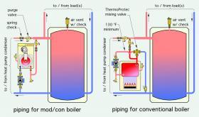
New or existing boilers fueled by natural gas or propane and designed to operate with sustained flue gas condensation can be piped the same as an electric boiler. Conventional boilers with heat exchangers made of cast iron, carbon steel or finned copper tubing are generally not designed to operate with sustained flue gas condensation. If one of these conventional boiler types is used in a low-temperature distribution system, it must be protected by a thermostatic mixing valve.
Figure 7-15 shows piping options for combining a mod/con or a conventional boiler into a system where an air-to-water heat pump supplies a 3-pipe buffer tank.
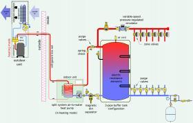
Another possibility is to use a buffer tank that has built-in electric heating elements, as shown in Figure 7-16.
This approach eliminates the need to pipe an external boiler and its associated circulator. It also reduces the space needed in the mechanical room. The downside to this approach is that servicing a failed electric heating element requires the tank to be taken offline and at least partially drained. There can be no heat flowing to the system when this type of service is required.
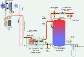
Yet another option is to use a heat pump with an inline electric heater incorporated into the indoor unit, as shown in Figure 7-17.
Controlling auxiliary heat
The auxiliary heat source can be automatically controlled in several ways. They include:
- Use of 2-stage room thermostat
- Use of 2-stage setpoint controller based on buffer tank temperature
- Use of 2-stage outdoor reset controller while monitoring buffer tank temperature
- Directly from the heat pump’s internal controller
2-Stage room thermostat
Two-stage room thermostats have been extensively used in single zone forced-air systems using air-to-air heat pumps equipped with electric strip heat. If the room thermostat was unable to maintain the room setpoint temperature using the heat pump alone, the 2nd stage of the thermostatic would operate a contactor that in turn turned on the electric strip heaters in the supply air plenum. It was also possible to set the thermostat to “emergency” mode when the heat pump was down for service. This would operate the electric strip heat as the system’s sole heat source. Two-stage room thermostats were designed for this type of low thermal mass, single zone system. As such they are not well-suited for higher thermal mass hydronic systems, especially those with multiple zones.
2-Stage setpoint control
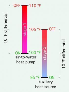
Two-stage setpoint control based on the temperature in a buffer tank is a simple control technique for a hydronic system where the air-to-water heat pump serves as the first stage heat source with a boiler serving as second stage heat source. A single temperature sensor in the buffer tank provided feedback to the 2-stage controller. Each stage of heat input has a setpoint and differential, both of which are adjustable. One possible control configuration for a low-temperature distribution system is given in Figure 7-18.
With these settings, the air-to-water heat pump would turn on when the tank temperature sensor dropped to 100ºF. It would continue to run until the tank temperature increased to 110ºF. The auxiliary heat source would only turn on if the tank temperature dropped to 95ºF. Once on, the auxiliary heat source would continue to run until the tank temperature climbed to 105ºF.
Modern digital temperature controllers allow the setpoint and differential of both stages to be adjusted over a wide range. The operating ranges can overlap, as shown in Figure 7-18, or not. The exact settings for a given system are usually determined by experience. They represent a compromise between not allowing excessively wide temperature swings that could negatively affect comfort, and preventing short cycling of the heat sources, which increases wear and ultimately shortens service life.
Some two-stage setpoint controllers also allow an interstage time delay to be in effect. This sets the minimum time that must elapse between when the stage 1 contacts close, and when the stage 2 contacts close. Providing a nominal 3- to 5-minute interstage time delay allows time for the air-to-water heat pump to reach a stable operating condition, and thus establish the likely temperature trending at the tank sensor (increasing, decreasing or stable). This helps prevent short cycling of the second stage heat source at times when the air-to-water heat pump will eventually be able to satisfy the load requirement.
Two-stage setpoint control is a good strategy when the buffer tank is expected to maintain a minimum temperature, regardless of the prevailing space heating load. One example is when the buffer tank will be used to preheat domestic water.
2-stage outdoor reset control
Two-stage outdoor reset control is similar in some ways to 2-stage setpoint control. The goal is to operate both heat sources as necessary to maintain a target water temperature in the buffer tank. That target temperature increases as the outdoor temperature decreases, and vice versa. Allowing lower target temperatures in the buffer tank under partial load conditions increases the heat pump’s
seasonal COP. This is a good control strategy when the buffer tank is only used to supply space heating.
Some 2-stage outdoor reset controllers are capable of rotating the operating order of the two heat sources. When an air-to-water heat pump is used, it should always be the stage 1 heat source. Thus, the “boiler rotation” function of the controller should be disabled.
Most 2-stage outdoor reset controllers use PID (Proportional Integral Derivative) logic to determine when the contacts for each stage are closed. The farther the water temperature in the buffer tank varies from the target value, the longer this deviation exists, and the faster the temperature is changing, the more “aggressive” the controller gets in operating the heat sources. The controller’s goal is to keep the measured water temperature in the buffer tank as close to the target value as possible.
Auxiliary heat source control logic within the pump
Some air-to-water heat pumps have relay contacts that automatically close when auxiliary heat is needed. These heat pumps have user settings to fine-tune when the auxiliary heating contacts will operate. These contacts may or may not be designed to directly operate 240 VAC heating elements. Designers should always verify the maximum ampacity of the auxiliary relay contacts. If the contacts do not have suitable ampacity, the auxiliary relay in the heat pump can be used as a “pilot relay” that energizes the coil of another contactor having contacts with sufficient ampacity.
Monitoring heat pump performance
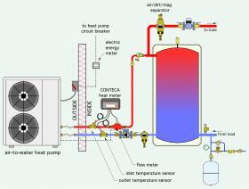
Modern heat meters, used in combination with electrical energy meters, make it possible to determine the heating output and COP of an air-to-water heat pump over a wide range of time intervals. Figure 7-19 shows how these meters would be installed.
The Caleffi CONTECA heat meter uses two precision temperature sensors to measure the difference between the fluid temperatures entering and exiting the heat pump (e.g., ∆T). It also accepts a signal from the flowmeter. By combining the instantaneous values of ∆T and flow rate, the CONTECA meter can calculate the rate of heat transfer. It can also integrate this calculation over time to determine the total thermal energy supplied by the heat pump. If a monobloc heat pump is used, the system will likely be operating with an antifreeze solution. Be sure the CONTECA meter has been configured for the fluid properties of that antifreeze solution.
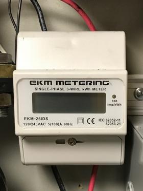
A small and relatively inexpensive electric meter, such as shown in Figure 7-20 can be used to gather electric energy use.
This particular meter doesn’t display instantaneous power. However, it does deliver 800 pulses per kilowatt-hour of electrical energy use. When connected to a typical residential heat pump drawing 3,000 to 4,000 watts, the average power over a time increment of 1 to 2 seconds could be determined by a pulse counting device.
The heat pump’s average COP over a given time increment can be calculated using Formula 7-2.
$$COP_{ave}={{Btu\,delivered}\over{{(kwhr\,used)\,·\,3413}}} $$
Where:
COPave = average COP of some time increment (hour, day, month, etc.)
kwhr used = number of kwhr metered over the same time interval
3,413 = number of Btus per kwhr
Domestic water heating options
There are several possible ways to use an air-to-water heat pump for domestic water heating. They include:
- Using a desuperheater
- Using an indirect water heater with large internal coil
- Using a reverse indirect water heat
- Using an "on-demand" external heat exchanger with flow switch
Desuperheater option
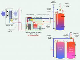
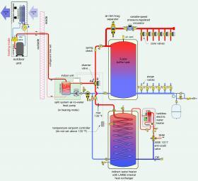
Some split system air-to-water heat pumps can be ordered with desuperheater heat exchangers. These were discussed in section 4. The desuperheater absorbs heat from the hot refrigerant vapor leaving the heat pump’s condenser and transfers it into a stream of domestic water. This heat transfer takes place whenever the heat pump’s compressor is operating, in heating or cooling mode. Some heat pumps turn off their internal desuperheater circulator when the leaving domestic water temperature reaches 130ºF. Figure 7-21 shows a typical piping arrangement for this approach to domestic water heating.
When the space heating system operates at low water temperature, or when the domestic hot water delivery temperature is high, the “two-tank” configuration is preferred. It allows the refrigeration system to operate at lower temperatures, which improves the heat pump’s COP.
Indirect tank option
Another option is to connect an indirect water heater as a priority zone. Since the water heater has several gallons of thermal mass, the buffer tank is bypassed in this mode of operation. One possible configuration is shown in Figure 7-22.
When this approach is used, it is critically important to specify an indirect tank with a large internal coil that allows the full rate of heat production from the heat pump to dissipate into the domestic water without forcing the heat pump’s condenser temperature above 130ºF. Failure to do this will cause the heat pump’s operating temperature to quickly rise to a value at which an internal safety control turns off the compressor.
It is also important to realize that the heat pump alone cannot generate domestic water temperature above pproximately 120ºF. When higher DHW delivery temperatures are needed, some form of supplemental heat input will be required. An electric tankless water heater is one option, as shown in Figure 7-22.
Some air-to-water heat pumps have internal controls that can treat domestic water heating as a priority load. When a contact in the setpoint controller monitoring water temperature in the indirect tank calls for heating, the heat pump powers on the diverting valve. This directs all flow from the heat pump through the internal coil of the indirect tank. Some air-to-water heat pumps can produce a leaving water temperature of up to 130ºF under this mode of operation. Be sure that the setpoint controller monitoring the water temperature in the tank is not set so high that the heat pump can never achieve the setting. A maximum suggested setting for the tank thermostat is 5ºF lower than the maximum leaving water temperature from the heat pump.
One advantage of this approach is that the buffer tank can function in both heating and cooling modes. If the heat pump is operating in cooling mode when a call for domestic water heating occurs, the heat pump switches to heating mode. The diverter valve directs the heated water through the coil of the indirect water heater. Chilled water in the buffer tank is still available to flow to cooling loads while the indirect tank is being heated.
Reverse indirect tank option
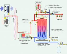
Another approach to domestic water heating uses a “reverse” indirect tank to preheat domestic water. A tank-type or tankless electric water heater serves as the supplemental heater. An example of this approach in a “heating only” system, is shown in Figure 7-23.
This approach allows the thermal mass of the reverse indirect to buffer space heating as well as domestic water heating. It eliminates the need of a second tank. The tank should be equipped with a large internal coil heat exchanger to minimize the temperature difference between the water in the tank shell and the domestic water inside the coils.
The system shown in Figure 7-23 configures the tank as a “2-pipe” buffer. A motorized ball valve is installed in the piping from the heat pump to the tank. This valve opens when the heat pump operates and closes at all other times. The valve has two purposes. First, it prevents water returning from the space heating zones from passing through the heat pump when it is off. If otherwise allowed, this flow would needlessly dissipate heat into the mechanical room and lower the temperature of the water supplied to the space heating zones. The motorized ball valve also prevents reverse thermosiphoning from the tank through the heat pump when the latter is off. This second function eliminates the need to install a check valve to prevent reverse thermosiphoning.
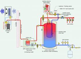
Another option is to use a “tank-in-tank” buffer, as shown in Figure 7-24.
The buffer tank has an internal stainless steel tank which holds domestic water. The inner tank is surrounded by heated water supplied from the heat pump and used for the space heating distribution system. Cold domestic water flows into the inner tank whenever hot water is drawn at a fixture. The temperature of the heated domestic water leaving the inner tank depends on the temperature of the water in the outer tank, as well as the rate at which domestic hot water is drawn. An electric tankless water heater is shown as a supplemental heater to boost the domestic water to the required delivery temperature. An ASSE 1017-rated mixing valve is used to ensure that the temperature of the water delivered to the plumbing distribution system doesn’t exceed 120ºF.
These approaches to domestic water heating could be used in a system that supplies chilled water for cooling. However, if the cooling distribution system is zoned, and the heat pump uses a fixed-speed compressor, a separate chilled water buffer tank would be required. If a variable-speed heat pump is used, and the cooling distribution system is not highly zoned, the chilled water buffer tank could likely be eliminated.
On-demand external heat exchanger option
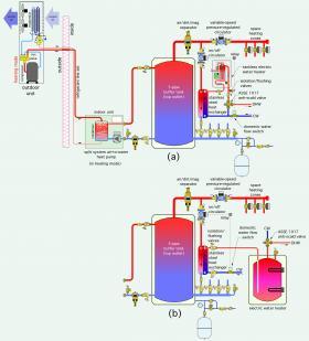
It’s also possible to use an external heat exchanger to preheat domestic water using heat from a buffer tank. This option is illustrated in Figure 7-25.
Whenever there is a draw for domestic hot water that exceeds some minimum threshold (typically 0.6 to 0.7 gpm in residential systems), a flow switch closes its contacts. This energizes a relay, or one zone in a multi-zone relay center, to power up a circulator that creates flow from the top of the buffer tank through the primary side of a stainless steel brazed plate heat exchanger. Cold domestic water passes in counterflow through the other side of this heat exchanger and absorbs heat. The temperature of the domestic water leaving the heat exchanger depends on the temperature at the top of the buffer tank and the size of the heat exchanger. A suggested guideline is to size the heat exchanger for a 5ºF approach temperature difference based on the average anticipated water temperature at the top of the tank and the design flow rate of cold domestic water entering the heat exchanger.
In Figure 7-25a, the preheated water leaving the heat exchanger passes through a tankless electric water heater, which supplies any necessary boost in temperature. Domestic hot water leaving the tankless heater passes through an ASSE 1017-rated mixing valve before flowing to hot water fixtures. It’s also possible to use a tank-type water heater in place of the tankless heater, as shown in Figure 7-25b.
In systems supplying heating and cooling, the circulator associated with the domestic water heat exchanger would be disabled during cooling mode operation. This would transfer the full domestic water heating load to the tankless water heater.
Chilled water cooling units
One of the foremost benefits of air-to-water heat pumps is their ability to provide both heating and cooling. The latter is provided as a stream of chilled water typically ranging in temperature from 45 to 60ºF. There are several potential ways to use chilled water to reduce the temperature of interior air, as well as lower its moisture content. Some of those details are discussed below.
Chilled water terminal units
The most common way of using chilled water for building cooling is to route it through copper tubing in a water-to-air heat exchanger, often called a “coil,” while room air passes by aluminum fins attached to the copper tubing. The air movement across the coil is created by a fan or a blower. This combination of hardware has several different names depending on its size and mounting location. They include:
- Fan-coil
- High wall cassette
- Air handler
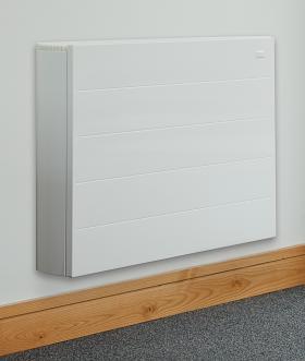
A fan-coil is intended to be mounted within a finished interior space. In most cases, it is located at the base of a wall just above the floor. Some fan-coils are surface mounted, others are mounted into a recessed cavity in the wall. Figure 7-26 shows an example of a modern surface-mounted fan-coil.
Any fan-coil used for chilled water cooling must include a condensate drip pan. This pan catches water droplets falling from the coil and routes them to a piping connection. A plastic drain tube then carries the condensate to a suitable drain.
Most fan-coils must be supplied by line voltage to operate the fan or blower. Some can be turned on and off by a single contact closure, while others are operated by a handheld remote. Most have integral controls that allow the fan speed to be set as desired.
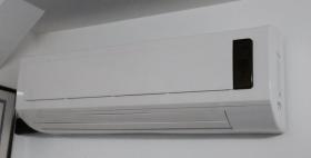
A high wall cassette is a special type of fan-coil designed to be mounted a few inches below ceiling level. An example is shown in Figure 7-27.
High wall cassettes draw in air at the top of the unit and discharge it through a slot at the front base. Most have an oscillating damper that opens when the unit is operating and closes when it is off. The movement of the damper is designed to mix discharge air with room air. Most high wall cassettes are operated by a handheld remote. Internal contacts within the cassette allow it to turn on a circulator or valve for either heating or cooling mode.
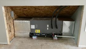
Air handlers are designed to be mounted in utility spaces and connected to ducting systems. Many modern air handlers can be mounted in either vertical or horizontal orientations. Figure 7-28 shows an example of the latter.
This air handler has a nominal cooling rating of 3 tons (36,000 Btu/hr). It is supplied with chilled water from a heat pump by a set of 3/4” pre-insulated PEX tubes. The condensate drain with trap is seen in the lower front of the unit. The condensate trap prevents the air handler from sucking in air through the drainage pipe. This trap is also equipped with an overflow switch that turns off the blower if a blockage within the trap prevents condensate from properly draining. Notice that the 3/4” PVC drain pipe is sloped downward for gravity drainage. This air handler is also mounted above a secondary drain pan, which would catch any water leaking from the primary drain pan.
The air handler is powered through a disconnect switch seen on the wall at the left of the opening. This air handler has a removable filter between the air intake plenum at the right and the air intake. The air handler is fully accessible by removing a panel not shown in the photo. This air handler could also be configured for vertical mounting by rotating the orientation of the chilled water “A-coil” within the cabinet.
The cooling ratings of fan-coils and air handlers are typically divided into two categories: sensible cooling and total cooling. Sensible cooling is the ability of the air handler to lower the temperature of air passing through it at a specific combination of entering water temperature, entering air temperature, water flow rate and airflow rate.
Latent cooling is the ability of the unit to remove moisture from the airstream passing through it. The latent cooling capacity of an air handler or fan-coil is found by subtracting sensible cooling capacity from total cooling capacity.
Cooling load calculations develop values for sensible and latent cooling capacity. Designers need to reasonably match the ratio of sensible-to-total cooling capacity of an air handler to the ratio of sensible cooling load-to-total cooling load. The latter would be determined through cooling load calculations.
Preventing unwanted condensation
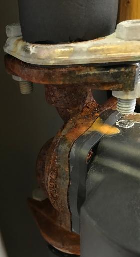
Perhaps the most critical detail on chilled water cooling systems is preventing condensation on piping and other components conveying chilled water. If surrounding air comes in contact with chilled surfaces that are below the dewpoint of that air, condensation will occur. This will cause superficial oxidation of any ferrous metal components, even those with a painted or coated surface, as seen in Figure 7-29.
The accumulating condensate will eventually drip from the piping and possibly damage whatever is under it. Such damage includes stained ceilings, deteriorating materials and eventual growth of mold and mildew.
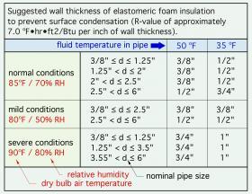
To prevent condensation, the outer surface of the pipe insulation must be maintained above the dewpoint of the surrounding air. Insulation manufacturers typically provide tables, such as shown in Figure 7-30, that relate the minimum insulation wall thickness required to prevent surface condensation to the temperature of the fluid in the tube, and the air conditions surrounding the insulation, including dry bulb temperature and relative humidity.
It is also important to use insulation that has a low vapor permeability, or to wrap insulation materials, such as fiberglass, that have relatively high vapor permeability with a continuous jacket that provides a vapor barrier. If such measures are not taken, the vapor pressure differential between the air surrounding the insulation and the cooler air near the pipe wall will cause vapor diffusion through the insulation. This vapor will condense on the pipe surface or within the insulation, and it could eventually saturate it with liquid water, leading to dripping, mold and significant loss of thermal resistance.
Closed-cell elastomeric foam insulations typically have low vapor permeability, as does cellular glass insulation. Acceptable vapor barriers for fiberglass or open-cell foam insulation include aluminum foil, PVC or composites using layers of paper, fiberglass scrim and aluminum foil.
Care should be taken to maintain the integrity of the insulation and its vapor barrier at all joints, as well as components such as valves, circulators, buffer tanks, unions and other pipe fittings. This often requires use of sheet insulation products, carefully fitted to irregular shapes and applied with compatible adhesives.
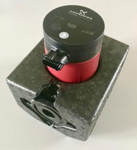
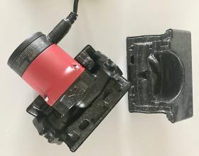
To be effective, these insulation shells must be fit tightly to the circulator volute and be sealed at all edges and seams to prevent air entry. It’s also important to insulate isolation flanges or valves. Carefully cut and fit elastomeric foam insulation is one possibility. Self-adhering elastomeric foam tap is another. The motor on a circulator should never be insulated because it inhibits heat dissipation, especially if the same circulator operates during heating mode.
These insulation and vapor sealing techniques also apply to devices that combine electrical components with fluid conveying components. Examples include zone valves, diverter valves and mixing valves.
Figure 7-32 shows adequately insulated zone valves. Notice that the valve bodies are insulated, but the electrical actuators are not.
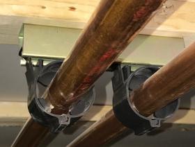
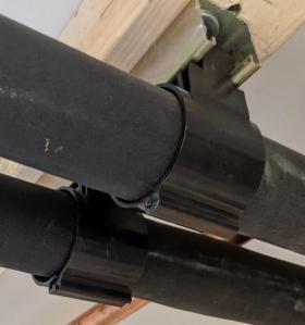
It is also important to support insulated piping that conveys chilled water so that the insulation does not undergo significant compression due to the forces transferred between the piping and its supports. Figure 7-33a shows one type of polymer tube support designed so that insulation can be nearly continuous along the copper tubing.
The polymer tube support hangs from a piece of channel strut and closes around the copper tube. Elastomeric foam insulation slides into the support from both directions. A final detail is to caulk the perimeter seam where the insulation and tube support meet, which is not shown in Figure 7-33b.

