PREFACE
The control subsystem is the “brain” of any hydronic heating or cooling system. It determines exactly when and for how long devices such as circulators, burners, compressors and mixing valves will operate. Even the best hydronic heat source, distribution system and heat emitters, cannot provide proper comfort without a well-planned control strategy.
This section gives an overview of the basic controllers used in modern hydronic heating systems. It also provides information on how the heat output of a system responds to changes in water temperature, as well as changes in flow rate, which is also essential when planning control strategies.
CONTROLLING HEAT OUTPUT
There are several ways to regulate the rate of heat delivery from a hydronic system to the building it serves. Fundamentally, they can be categorized as follows:
• Turn the heat source and distribution circulator on and off
• Regulate the temperature of the water supplied to the heat emitters
• Regulate the flow rate of water passing through heat emitters.
ON/OFF CONTROL OF HEAT SOURCE
Many of the heat sources (e.g., boilers, heat pumps, etc.) used in residential and light commercial hydronic systems have only two operating modes: on or off. Whenever the heat source is on, it produces heat at a fixed rate. When the heat source is off, it produces no heat output. Such heat sources require a simple on/off control signal from their controller. This is typically provided by the closing and opening of an electrical contact.
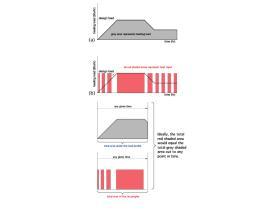
The total amount of heat added to the system over time is regulated by periodically turning the heat source on and off. This is illustrated in Figure 10-1.
Figure 10-1a shows a hypothetical heating load profile (e.g., the rate of heat delivery required by the load over time). The load begins at zero, rises at a constant rate to its maximum design value and then decreases back to half its design value. The time over which this occurs can be assumed to be a few hours.
Figure 10-1b shows how a heat source operated by an on/ off controller supplies heat to this load. The red-shaded rectangles represent heat input from the heat source. The height of the rectangles remains the same because the rate of heat delivery is constant whenever the heat source is on. In this case, that rate matches the design load (e.g., the maximum required load).
The width of the rectangles increases as the load increases. This means that the duration of the on-cycle is increasing. When design load occurs, the rectangle remains uninterrupted. Since the heat source is sized to the design load of the building, it must operate continuously whenever design load conditions exist. As the load decreases, the rectangles become narrower. When the load stabilizes at 50% of design load, the width of the rectangles remains constant. Under this condition, the heat source is on 50% of the time. When on, its rate of heat output is twice the rate at which the building requires heat.
The area of each red-shaded rectangle represents the quantity of heat delivery by the heat source during its on cycle. Ideally, the gray-shaded area under the load profile, from when the load begins and out to some point in time, exactly equals the total area of the red-shaded rectangles over that same time. This implies that the total heat production of the heat source exactly matches the total load over that period.
The match between heat output and heating load at low and medium load conditions is not ideal. For example, consider the time when the load is very small. Under such conditions, the heat source sends short pulses of heat to the load. The height of these pulses corresponds to the full heating capacity of the heat source, which under partial load conditions may be several times higher than the load.
In heating systems with low thermal mass, this on/off cycling of the heat source is often noticeable and generally undesirable. A forced-air furnace with a constant-speed blower and fixed firing rate is an example of such a system. Under partial load conditions, the furnace produces its full rate of heat output whenever it is on. Since the air in the building, along with the metal in the furnace’s heat exchanger, provides very little thermal mass for absorbing this heat, the air temperature in the building increases quickly. When the thermostat reaches its setpoint temperature, its contacts open and the furnace is turned off. An operating cycle could be as short as 2 or 3 minutes under partial-load conditions.
During this time, the occupants sense the rapidly changing room air temperature and usually do not like it. These short operating cycles repeat themselves as long as the load persists at its present level.
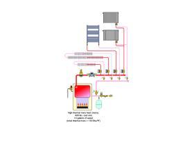
Many hydronic systems, especially those having high thermal mass embodied by the heat source, buffer tank or high mass heat emitters, have an advantage in this respect. Their greater thermal mass can temporarily absorb some of the surplus heat output generated by the heat source and spread out its delivery over time. This helps stabilize room temperatures. The system shown in Figure 10-2 is an example.
The heat source is assumed to be a small cast iron boiler. The heat exchanger in a typical small cast-iron boiler contains approximately 400 pounds of cast iron and 10 gallons of water. The combined thermal mass of the metal and water allow the boiler to continue delivering heat to the zoned distribution system for several minutes after the burner has turned off. After the boiler’s thermal mass has cooled by several degrees, the burner is turned back on and will likely operate for several minutes before the water temperature leaving the boiler can again climb high enough to turn the burner off. This prevents “short cycling” of the burner. Longer on-cycles also improve combustion efficiency and reduce emissions.
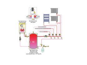
Systems with low-mass heat sources, such as certain types of mod/con boilers or water-to-water heat pumps, often require additional mass to prevent short cycling.
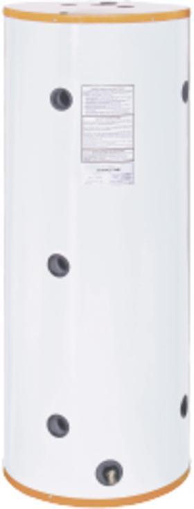
Buffer tanks, such as the Caleffi ThermoCon tank shown in Figure 10-4, can be sized to provide a specific minimum on-cycle. A commonly accepted minimum on-cycle for boilers and heat pumps is 10 minutes. Appendix B provides relatively simple formulas for determining the required volume of the buffer tank based on the heat capacity of the heat source, and a specified minimum on-cycle.
ON/OFF SETPOINT TEMPERATURE CONTROL
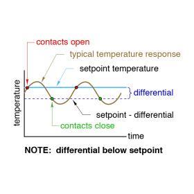
Many control actions in hydronic systems are initiated and terminated based on temperature. An example would be burner operation in an on/off gas-fired boiler. When there is a “call” for heat by some other controller in the system, control authority is given to the boiler’s high-limit controller. If the water temperature in the boiler is at or below the current “setpoint” of the high-limit controller minus a specific “differential,” the burner is turned on. When (and if) the water temperature in the boiler reaches the setpoint temperature of the high-limit controller, the burner is turned off. This control action is illustrated in Figure 10-5.
The “differential” of a setpoint temperature controller is the difference in temperature between where the electrical contacts on the controller close and when they open. Some setpoint temperature controllers place the differential below the setpoint, as shown in Figure 10-5. For example, if the setpoint of the controller is 140ºF and the differential is 10ºF, the electrical contacts on the controller would close when the temperature being sensed drops to 130ºF (e.g., 140ºF - 10ºF differential). These contacts would reopen if and when the temperature rises to 140ºF.
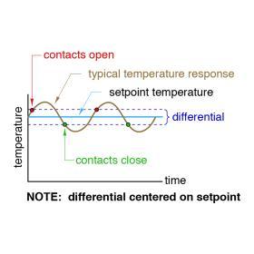
Other setpoint controllers center the differential on the setpoint temperature, as shown in Figure 10-6. In this case, if the setpoint was 140ºF and the differential was 10ºF, the contacts would close at 135ºF and reopen at 145ºF.
Both the setpoint and differential are adjustable on most temperature setpoint controllers used in hydronic heating and cooling systems. Setting the differential involves a compromise: The greater the differential, the longer the on and off cycles of the controlled device will be. This is generally considered beneficial to the life expectancy of devices such as burners or compressors. However, the wider the differential, the greater the variation in temperature between the desired setpoint and what the temperature may be at any given time. If the actual temperature varies too far from the setpoint, comfort and efficiency may be negatively affected.
A typical room thermostat is also a temperature setpoint controller. When the room air temperature drops slightly below the setpoint of the thermostat, it closes its electrical contacts to initiate a “call” for heat from the remainder of the system. When the room air temperature rises and approaches the setpoint, the thermostat’s contacts open to stop further heat generation by the heating system.
FLOATING CONTROL
Floating control was developed to operate motorized valves or dampers that need to be powered open as well as powered closed. In hydronic heating systems, floating control is commonly used to drive 3-way and 4-way motorized mixing valves.
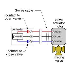
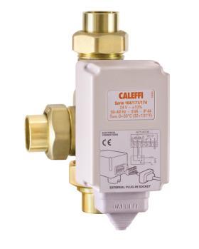
Figure 10-7 shows how a controller operating with floating control would be wired to a typical motorized mixing valve (an example of which is seen below the schematic).
With floating control, the controlled device is always in one of three possible states:
1. The controlled device is opening
2.The controlled device is closing
3. The controlled device is holding its current position
These states are created by the status of two normally open relay contacts within the controller, as seen in Figure 10-7. One electrical contact closes to drive the controlled device’s actuating motor in a clockwise (CW) direction. The other electrical contact closes to drive the actuator motor counterclockwise (CCW). Only one contact can be closed at any time. The actuating motor driving the controlled device turns very slowly. Some actuating motors can take up to three minutes to rotate the shaft of a valve or damper over its full rotational range of 90 degrees. This slow operation is desirable, since it allows the sensor ample time to provide feedback to the controller for stable operation.
Floating control is sometimes also called “3-wire control” because three wires are required between the controller and the actuating motor of the controlled device.
MODULATING TEMPERATURE CONTROL
Some control actions used in hydronic heating systems require gradual changes within a predetermined range. For example, depending on the current heating load, the firing rate of a burner in a mod/con boiler may need to vary from full output down to about 20% of that output. Another example would be where the speed of a circulator has to vary from completely off to full speed. These control actions are provided by controllers with modulating output signals.
Modulating controllers output a continuous electrical signal, either 2 to 10 volts DC or 4 to 20 milliamp current. The value of this voltage or current within its overall range is what determines the response of the controlled device. For example, a controller output signal of 2 volts or less supplied to a motor is “instructing” the motor to remain off. A 10-volt DC signal to the same motor means that it should be operating at full speed. A signal of 6 volts DC, which is 50% of the overall range of 2 to 10 volts, means that the motor should be running at 50% of full speed.
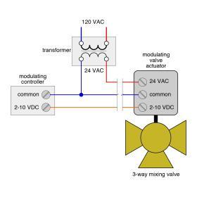
Keep in mind that these variable DC outputs are for control only and do not supply the electrical power to drive the device. For example, the typical wiring of a 2 to 10 VDC modulating valve is shown in Figure 10-8. Notice that 24 volts AC power must also be supplied to the valve to power the motor and the actuator’s circuitry. Likewise, a variable-speed pump that is controlled by a 2 to 10 VDC or 4 to 20 milliamp signal typically requires line voltage (120 VAC) to supply operating power.
The reason these control signals do not begin at zero voltage or current is to prevent electrical interference or “noise” from affecting the controlled device. This electrical noise can come from nearby motors, electrical wiring or certain types of lighting.
CONTROLLING HEAT OUTPUT FROM HEAT EMITTERS
There are two fundamental methods of controlling the heat output of hydronic heat emitters:
1. Vary the water temperature supplied to the heat emitter while maintaining a constant flow rate through the heat emitter
2. Vary the flow rate through the heat emitter while maintaining a constant supply water temperature to the heat emitter
Both approaches have been successfully used in many types of hydronic heating applications over several decades. It is important for system designers to understand the differences, as well as the strengths and weaknesses, of each approach.
VARIABLE WATER TEMPERATURE CONTROL
The heat output of any hydronic heat emitter is approximately proportional to the difference between supply water temperature and room air temperature. This can be represented mathematically as Formula 10-1:
$$ Q_o = k \left( T_s - T_r \right) $$
Where:
$Q_o$= rate of heat output from heat emitter (Btu/hr)
$k$= a constant dependent on the heat emitter used
$T_s$= fluid temperature supplied to the heat emitter (ºF)
$T_r$= air temperature of room where heat emitter is located (ºF)
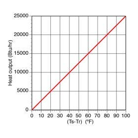
A graph of Formula 10-1 is a straight line, as shown in Figure 10-9. For this graph, the value of “k” in Formula 10-1 is 250.
If water is supplied to the heat emitter at room temperature (whatever that temperature happens to be), there will be zero heat output from the heat emitter. As the temperature of the water supplied to the heat emitter climbs above room air temperature, its heat output also increases. This graph shows that when the supply water temperature is 50ºF above the room air temperature, the heat emitter will release 12,500 Btu/hr into the room. If the supply water temperature climbs to 100ºF above the room’s air temperature, the heat emitter releases 25,000 Btu/hr into the room. Thus, doubling the temperature difference doubles the heat output.
The slope of the line in such a graph depends on the characteristics of the heat emitter. The greater the ability of the heat emitter to release heat at a given supply water temperature, the steeper the slope of the line.
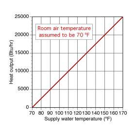
If one assumes a desired room air temperature of 70ºF, the graph shown in Figure 10-9 can be modified to that shown in Figure 10-10.
The only difference is that the supply water temperature is now shown on the horizontal axis. This proportional relationship between supply water temperature and heat output holds true, as a reasonable approximation, for most hydronic heat emitters. It is an important characteristic in the context of another control technique called outdoor reset control.
OUTDOOR RESET CONTROL
As outdoor temperatures change, so does the heating load of a building. Ideally, every heating system would continually adjust its rate of heat delivery to match its building’s current rate of heat loss. This would allow inside air temperature to remain constant regardless of outside conditions. Outdoor reset control was developed to do this by changing the temperature of the water supplied to the system in response to outdoor temperature.
An outdoor reset controller continuously calculates the ideal “target” supply water temperature to a hydronic system. This temperature depends on the type of heat emitters in the system, as well as the current outdoor temperature. It therefore has the potential to change from one moment to the next.
Outdoor reset controllers use Formula 10-2 to calculate the target water temperature that (ideally) should be supplied to a given hydronic distribution system at any given time.
$$ T_{target} = T_{indoor} + (RR) \times (T_{indoor} - T_{outdoor}) $$
Where:
$T_{target}$= the “ideal” target supply water temperature to the system
$T_{indoor}$= desired indoor air temperature
$RR$= reset ratio (slope of reset line)
The reset ratio (RR) is determined as follows:
$$ RR = {(T_{wd}-T_{wnl}) \over (T_{anl}-T_{ad})} $$
Where:
$T_{wd}$= required supply water temperature to distribution system at design load
$T_{wnl}$= water temperature supplied to distribution system at no load
$T_{anl}$= outdoor air temperature at design load
$T_{ad}$= outdoor air temperature at no load
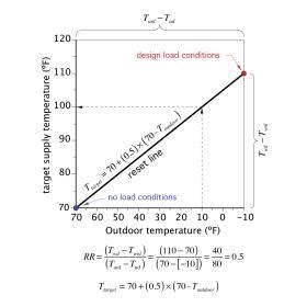
The graph in Figure 10-11 is a good way to visualize these relationships.
The red dot in the upper right portion of the graph represents design load conditions (e.g., the coldest day of winter). The blue dot in the lower left corner represents
no load conditions (e.g., where no heat output is needed from the heat emitters). The sloping line that connects these two dots is called the reset line.
The reset ratio (RR) is the slope of the reset line. It is found by dividing the vertical temperature difference between the red dot and blue dot by the horizontal temperature difference between the same dots. For the case represented in Figure 10-11, the reset ratio is:
$$ RR = {(T_{wd}-T_{wnl}) \over (T_{anl}-T_{ad})} = {(100-70) \over (70-[-10])} = {40 \over 80} = 0.5$$
The graph of a reset line can be used to find the target water temperature for any outdoor temperature. First, locate the outdoor temperature on the horizontal axis. Next, draw a vertical line up to intersect the reset line. Finally, draw a horizontal line from this intersection to the vertical axis and read the required target water temperature. For example, when the outdoor temperature is 10ºF, the reset line in Figure 10-11 indicates the target supply water temperature is 100ºF.
The target water temperature can also be determined by entering the outdoor temperature into the formula for the reset line. For the line shown in Figure 10-11, the target water temperature when the outdoor temperature is 10ºF would be:
$$ T_{target} = 70 +(0.5) \times (70 - 10) = 70 + 30 = 100^o F $$
IMPLEMENTING OUTDOOR RESET CONTROL
There are three ways to implement outdoor reset control in hydronic systems:
• Heat source reset (for on/off heat sources)
• Heat source reset (for modulating heat sources)
• Mixing reset
These techniques can be used individually or together.
HEAT SOURCE RESET (FOR ON/OFF HEAT SOURCES)
The temperature of water supplied to a distribution system can be controlled by turning a heat source such as a boiler or heat pump on and off.
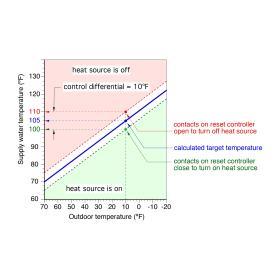
The graph in Figure 10-12 illustrates the control logic used by a reset controller that controls an on/off heat source. The sloping blue line represents the “target temperature” (e.g., the ideal supply water temperature for the distribution system over a range of outdoor temperatures). For example, if the outdoor temperature is 10ºF, the blue line in Figure 10-12 indicates a target temperature of 105ºF (as indicated by the blue dot).
When the reset controller is powered on, it measures both outdoor temperature and the current supply water temperature. It then uses the measured outdoor temperature, along with its settings, to calculate the target temperature. Then it compares the calculated target temperature to the measured supply water temperature.
If the measured supply water temperature is equal or close to the target temperature, no control action is taken. However, if there is sufficient deviation between these temperatures, the reset controller takes action.
The settings represented in Figure 10-12 would result in the following control actions when the outdoor temperature is 10ºF:
• If the water temperature supplied to the distribution system is above 100ºF (e.g., 105 less one half the differential of 10ºF), the contacts in the reset controller remain open and the heat source remains off.
• If the water temperature supplied to the distribution system is below 100ºF, the contacts in the reset controller close to turn on the heat source. Once turned on, the heat source would remain on until the water supplied to the distribution system reaches 110ºF (105 plus one half the control differential) or higher
The 10ºF differential between the temperatures at which the heat source is turned on and off discourages short cycling. The value of the differential can be adjusted on most outdoor reset controllers. Smaller control differentials reduce the variation in supply water temperature both above and below the target temperature. However, if the control differential is too small, the heat source will cycle on and off excessively. This is not good for the life of components such as boiler ignition systems or heat pump compressors and contactors.
HEAT SOURCE RESET (FOR MODULATING BOILERS)
Many modern boilers, and even some heat pumps, can adjust their heat output over a relatively wide range. This is called modulation, and it allows the heat source to better match the heating load. Modulation reduces issues such as short cycling and temperature variations that are more common in systems using on/off heat sources.
Modulating heat sources usually have their own internal outdoor reset controllers. They continually measure outdoor temperature, calculate the target supply water temperature and compare it to the measured supply water temperature. Deviations between these temperatures cause the internal reset controller to regulate the speed of the combustion air blower on a modulating boiler or compressor speed on a modulating heat pump. The goal is to keep the measured supply temperature very close to the calculated target temperature.
MIXING RESET
Outdoor reset control can also be implemented by a mixing assembly such as 3-way and 4-way mixing valves or a variable-speed injection mixing pump. The logic used for mixing reset is similar to that already described for modulating heat sources. The outdoor temperature is measured. The target temperature is then calculated. The measured supply temperature is then compared to the target temperature. The deviation between these temperatures determines the output signal from the reset controller to the mixing assembly. The goal is the same—to keep the water temperature supplied to the distribution system at, or very close to, the calculated target temperature.
For a more in-depth discussion on Mixing reset:
CONTROLLING HEAT OUTPUT USING FLOW RATE
The flow rate through any heat emitter affects its heat output. The following principle always applies:
The faster a heated fluid passes through a heat emitter, the greater the rate of heat transfer, all other conditions being equal.
It might seem intuitive to assume that heat transfer from a heat emitter increases in proportion to flow rate through it (i.e., doubling the flow rate through the heat emitter would double its heat output). Unfortunately, this is not true. The rate of change of heat output from any hydronic heat emitter is a strong function of flow rate. At low flow rates, heat output rises rapidly with increasing flow, but the greater the flow rate becomes, the slower the rate of increase in heat output.
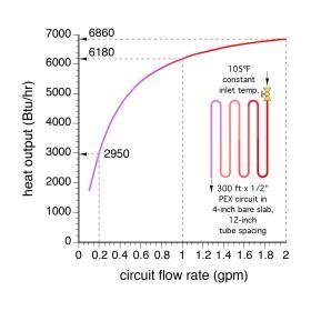
To illustrate this, consider the situation shown in Figure 10-13, which shows the heat output of a typical radiant floor circuit versus the flow rate through it. This circuit is supplied with water at a constant temperature of 105ºF.
The circuit’s maximum heat output of 6,860 Btu/hr occurs at the maximum flow rate shown (2.0 gpm). Decreasing the circuit’s flow rate by 50% ( to 1.0 gpm) decreases its heat output to 6,180 Btu/hr, a drop of only about 10%. Reducing the flow rate to 10% of the maximum value (to 0.2 gpm) still allows the circuit to release 2,950 Btu/hr, about 43% of its maximum output.
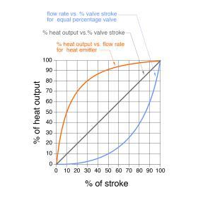
This “non-linear” relationship between heat output and flow is typical of all hydronic heat emitters. It tends to make adjusting heat output with a valve more complicated than what one might assume. For example, as a technician first begins closing a standard globe valve that is used for balancing a hydronic circuit, there is relatively little change in the heat output of the circuit. However, when that valve is only 10% to 25% open, small adjustments will yield relatively large changes in heat output.
Special types of valves with equal percentage characteristics have been developed to compensate for the rapid rise in heat output low flow rates. These valves allow flow rate to rise very slowly as they first start to open. The farther the valve stem is opened, the faster flow through the valve develops. The resulting combination provides a more proportional relationship between the position of the valve stem and the rate of heat output from the heat emitter being regulated by the valve, as shown in Figure 10-14.
For a more in-depth discussion on Controlling heat output using flow rate:
MIXING FUNDAMENTALS
The water temperature supplied to a hydronic distribution system is often controlled by a device that blends hot water from the heat source with cooler water returning from the distribution system. An example would be water supplied at 140ºF from the storage tank of a solar thermal system being blended with water at 90ºF returning from a radiant floor distribution system in proportions that create a supply water temperature of 110ºF back to the distribution system.
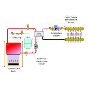
In hydronic systems, mixing takes place within a “mixing assembly.” This assembly can be composed of several different devices, such as valves, controllers or variable-speed circulators. However, the thermodynamics of mixing are independent of the specific hardware used within the mixing assembly. Thus, the mixing assembly can be considered as a “bridge” between the heat source loop and the distribution system, as shown in Figure 10-15. Notice that all heat passing from the heat source to the distribution system must pass through the mixing assembly.
PURPOSE(S) OF MIXING
One purpose of all mixing assemblies is to provide the proper supply water temperature to the distribution system.
When a conventional boiler (e.g., a boiler that requires protection against sustained flue gas condensation) serves as the heat source, the mixing assembly must also provide that protection. It typically does so by sensing the water temperature entering the boiler. If that temperature is at or below some present minimum value (usually around 130ºF for gas-fired boilers), the mixing assembly restricts the rate at which heat is allowed to pass from the boiler loop to the distribution system. Providing this protection requires the mixing assembly to continually monitor boiler input temperature.
THERMODYNAMICS OF MIXING
The first law of thermodynamics states that energy cannot be created or destroyed—only changed in form. This principle always holds true when flow streams are mixed together in hydronic heating systems. In such applications, it is convenient to express the first law as follows:
The rate of heat flow into a mixing assembly must equal the rate of heat flow out of the assembly.
It is also true, based on a principle called conservation of mass, that the flow rate of an incompressible fluid entering any fluid-filled component in a hydronic system must equal the flow rate leaving that component. Common hydronic system fluids like water or a mixture of water and antifreeze are incompressible, and thus this relationship must hold true. For a mixing assembly, it can be stated as:
The total flow rate of fluid entering a mixing device must equal the total flow rate of fluid leaving the mixing device.
When these two physical relationships are combined mathematically, the result is a simple but powerful formula for determining the temperature on the outlet side of any mixing device. It is stated in Formula 10-4:
$$ T_{mix} = {(T_1 \times f_1) + (T_2 \times f_2) \over f_1 + f_2} $$
where:
$T_{mix}$= resulting temperature of the mixed fluid stream
$T_1$= entering temperature of fluid stream #1
$T_2$= entering temperature of fluid stream #2
$f_1$= flow rate of fluid stream #1
$f_2$= flow rate of fluid stream #2
The temperatures and flow rates used in Formula 10-4 can be expressed in any consistent system of units. This formula applies to water and other fluids, such as antifreeze solutions, provided the same type of fluid enters both inlets to the mixing assembly.
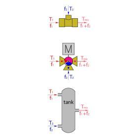
This formula also holds true regardless of the physical device in which the fluid streams come together. It applies to a tee, a tank, or any type of mixing valve, as illustrated in Figure 10-16.
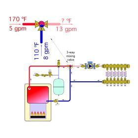
Example: Hot water is supplied from a conventional boiler at a temperature of 170ºF and flow rate of 5 gpm. It flows into the hot port of a 3-way mixing valve as shown in Figure 10-17. Cooler water returns from the distribution system at 110ºF and 8 gpm. Determine the mixed supply water temperature to the distribution system under these conditions.
Solution: Enter the values for temperature and flow rate of each entering fluid stream entering into Formula 10-4 and solve:
$$ T_{mix} = {(T_1 \times f_1) + (T_2 \times f_2) \over f_1 + f_2} = {(170 \times 5) + (110 \times 8) \over 5 +8} = 133^oF$$
For a more in-depth discussion on Thermodynamics of Mixing:
PRIORITIZED LOADS
There are many hydronic heating systems that supply more than just space heating. Some common “ancillary” loads include domestic water heating, snow-melting and pool heating. When designing the heat source for such systems, some designers add up all the heating capacity required by all of these loads, assuming they might operate at the same time, then size the heat source to supply the total.
Although this practice might seem intuitive, it is very seldom necessary. The diversity of when these loads require heat, as well as the timespan over which they can accept heat, often allows the heat source to be sized significantly smaller than the total of all connected loads. This, in combination with “prioritized load management,” allows for lower installed cost and higher operating efficiency.
Prioritized load management refers to assigning a specific “priority” to each of the connected loads. The higher the priority of the load, the sooner it will receive available heat from the heat source.
One of the most common scenarios in hydronic systems is assigning top priority to domestic water heating, along with subsequent priority to space heating. Loads such as pool heating are generally assigned lower priority because their high thermal mass allows for gradual temperature changes over several hours. Thus, they can accept heat from the heat source at almost any time of day without undergoing temperature changes of more than a few degrees.
Priority control can be accomplished using hard-wired relay logic or with a prebuilt multi-zone relay center that includes priority logic. The latter is the fastest and easiest way to implement priority control.
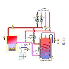
Consider the system shown in Figure 10-18. It consists of two space heating zones, each operated by independent circulators (P2) and (P3). Domestic hot water is provided by an indirect water heater with internal heat exchanger. Circulator (P1) operates to move hot boiler water through this heat exchanger whenever the tank’s thermostat calls for heat.
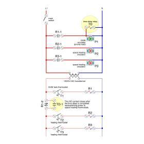
If priority is to be given to domestic water heating, circulators (P2) and (P3) must turn off when circulator (P1) is operating. The ladder diagram in Figure 10-19 shows the relay logic used to do this.
Upon a call for heat from the tank thermostat (T1), the coil of relay (R1) is powered on by the 24 VAC circuit. Relay contact (R1-1) closes to supply line voltage to the DHW circulator. This contact also supplies 120 VAC to power on a time delay relay (TD-1). This time delay relay uses a “delay-on-make” configuration. As such, its normally open contacts will only close after a preset time has elapsed. For priority DHW control, this time is typically set for 30 minutes..
Another relay contact associated with relay (R1) is located in the low voltage portion of the ladder diagram. The contacts (R1-2) are normally closed. As such, they open when relay (R1) is powered-on. This interrupts 24 VAC to all space heating thermostats, which turns off any active space heating zones.
At this point, the domestic water heating load is active, all space heating zones are off and the timer in relay (TD-1) is counting towards 30 minutes. If the domestic water thermostat is satisfied within 30 minutes, relay (R1) is turned off and 24 VAC is resupplied to the space heating thermostats. If the domestic water thermostat is not satisfied within 30 minutes, the normally open contact (TD-1), wired in parallel with contact (R1-2), closes. This re-establishes 24 VAC to the space heating thermostats and allows the domestic water heater to continue operating. This latter function is called priority override. It prevents a long-term “lockout” of space heating in the event that the domestic water heating load cannot be satisfied.
For a more in-depth discussion on Prioritized Loads:

