PREFACE
A hydronic distribution system is an arrangement of pipes, valves and one or more circulators that conveys heat from the heat source and delivers it to the heat emitters. Distribution systems can be specifically tailored to the needs of each building, taking into account factors such as the type of heat sources used, the kind(s) of heat emitters used, how the building will be zoned and the ease (or lack thereof) of installing piping within a building.
TRADITIONAL HYDRONIC DISTRIBUTION SYSTEMS
The majority of hydronic distribution systems used in North America over the last several decades were designed around rigid metal pipe. This section describes these traditional designs and discusses their individual strengths and limitations. It then moves on to discuss more contemporary distribution systems that make use of flexible tubing and modern methods of zoning.
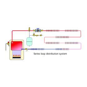
SERIES LOOP SYSTEMS
• The temperature of the water decreases as flow passes from one heat emitter to the next. Proper design requires that each heat emitter be sized for the water temperature at its location within the circuit. If, instead, each heat emitter is sized for the average circuit water temperature, those near the beginning of the circuit will be oversized, and those near the end of the circuit will be undersized. In such cases, complaints of underheating from the heat emitters near the end of the circuit are likely. The longer the series circuit, the more pronounced this effect becomes.
• The total head loss of a series circuit is the sum of the head loss of each component in that circuit. The circulator must supply this total head loss as the design flow rate. Designers must avoid creating series circuits with excessively high head loss. Such a situation can occur if a component with relatively high flow resistance is included in the circuit, especially if combined with several heat emitters that also create significant head loss. If the circuit’s head loss is high, it may become necessary to use a “high head” circulator. Such circulators often draw two to three times more wattage than standard circulators, which results in significantly higher operating cost. Insufficient flow through a high-head-loss series circuit can also result in reduced heat output.
• All heat emitters in the series loop provide simultaneous heat output. It is not possible to zone on a room-byroom basis using a series loop. Changing the flow rate or supply water temperature affects the heat output of all heat emitters on the circuit. For this reason, all rooms served by a series circuit should be considered as a single zone. If some rooms experience significant internal heat gains and others do not, a series circuit should not be used. In general, series circuits should be limited to relatively open floor plans where all areas are to be maintained at the same comfort level.
DIVERTER TEE SYSTEMS
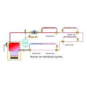
Similar in some respects to series loops, diverter tee distribution systems use a special fitting called a diverter tee to route some of the flow in the main piping circuit through a branch path containing one or more heat emitters. Figure 9-2 shows an example of such a system.
A valve is often installed in each branch to regulate flow through the heat emitter(s) in that branch. This valve may be manually operated, electrically operated or a thermostatic radiator valve. By controlling the flow in each branch, it’s possible to provide room-by-room comfort control (provided there is always flow in the main circuit whenever any branch requires heating).
One diverter tee, installed on the return side of the branch, usually provides sufficient flow when that branch is located above the main pipe. If the branch circuit is long, contains several heat emitters or is located below the main pipe, two diverter tees, one “pushing” and the other “pulling,” are generally recommended. In either case, there should be a minimum of one foot of straight pipe between the upstream and downstream tees to minimize turbulence. Always be sure the diverter tees are installed in the proper direction.
Diverter tee distribution systems have the following characteristics:
• As with a series loop, water temperature decreases in the direction of flow along the main pipe. This circuit temperature drop depends on which branches are active at any given time. Designers should size heat emitters assuming all branches are operating simultaneously.
• Each diverter tee adds significant flow resistance to the main circuit. It is not uncommon for a diverter tee fitting to have an equivalent length of at least 25 feet of straight tubing. Adding several diverter tees to a circuit significantly increases the head loss of that circuit, and thus the head required from the circulator to achieve a given flow rate. Designers should carefully assess this effect when designing the circuit and selecting a circulator.
• The only significant advantage a one-pipe diverter tee distribution system has over a series loop system is when valves are used to control flow through each branch. This advantage comes at an associated higher installation and operating cost. Other types of distribution systems are better suited to control the flow through each heat emitter.
“2-PIPE” DIRECT RETURN SYSTEMS:
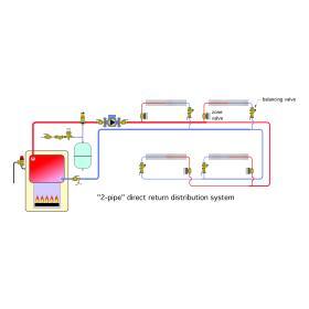
Hydronic heat emitters can also be piped in a parallel rather than series. One approach puts each heat emitter in its own “crossover” pipe, which connects to a common supply and return main, as shown in Figure 9-3. This configuration is called a “2-pipe” direct return distribution system.
Two-pipe direct return systems have the following characteristics:
• Each heat emitter receives fluid at approximately the same temperature. This simplifies sizing, since the water temperature drop associated with series loops and diverter tee systems is eliminated.
• The heat emitter closest to the circulator on the supply main is also closest to the circulator on the return main. The next heat emitter connected to the supply main has a greater length of piping between it and the circulator. The heat emitter farthest away from the circulator has the longest overall piping path length. If each crossover in the system has the same flow resistance, the highest flow rate will be through the shortest piping path. If uncorrected, this situation reduces the flow rate through heat emitters located farther away from the circulator. Balancing valves installed in each crossover allow flow rates to be adjusted in proportion to the required heat output.
• Flow through each crossover can be controlled using either an on/off zone valve or a modulating flow control valve. This allows each heat emitter to be independently controlled, and thus room-by-room zoning is possible when the system is properly configured.
• Different types of heat emitters can be used on the various crossovers provided they are all sized for the same supply water temperature.
“2-PIPE” REVERSE RETURN SYSTEMS
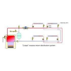
If the piping design used for the direct return system of Figure 9-3 is modified as shown in Figure 9-4, the result is called a “2-pipe” reverse return system.
Notice that the heat emitter closest to the circulator along the supply main is now farthest from the circulator on the return main. This makes the length of the piping path to and from the circulator approximately the same for each crossover.
If each crossover has the same flow resistance, and if the supply/return mains are sized for approximately the same head loss per unit of length at all locations in the system, this configuration is largely self-balancing. However, balancing valves should still be installed , because the flow resistance through each heat emitter and its associated crossover will not always be the same.
Reverse return systems are well-suited to applications where the supply and return mains run side by side and make a loop from the mechanical room around the building and back to the mechanical room.
2-pipe reverse return systems have the following characteristics:
• Each heat emitter receives water at approximately the same temperature. This simplifies heat emitter sizing because the water temperature drop associated with series loops and diverter tee systems is eliminated.
• Flow through each crossover can be controlled using either an on/off zone valve or a modulating flow control valve. This allows each heat emitter to be independently controlled, and thus room-by-room comfort control is possible when the system is properly configured.
• Different types of heat emitters can be used on the various crossovers provided they are all sized for the same supply water temperature.
• 2-pipe reverse return systems are often favored over 2-pipe direct-return systems because they are closer to self-balancing.
ZONING USING CIRCULATORS
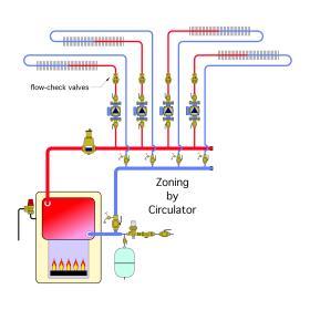
A traditional North American approach for creating multizone hydronic systems uses a separate circulator for each zone circuit, as shown in Figure 9-5.
When a zone needs heat, the associated circulator and the boiler are turned on. When a zone thermostat is satisfied, its circulator is turned off. When all the thermostats are satisfied, the boiler is turned off. All zone circuits begin and end at headers. These headers should be sized for a maximum flow velocity of 2 feet per second to provide good hydraulic separation between the circulators.
Notice that each zone circuit contains a flow-check valve. This valve can be a separate component mounted downstream of the circulator, as shown in Figure 9-5, or it can be integral to the circulator. The flow-check valve prevents reverse flow through inactive zone circuits while other zones are operating. It also prevents buoyancy-driven hot water migration through inactive zone circuits. Each zone circuit should also be equipped with its own purging valve to expedite air removal during start-up and servicing.
Zone circulator systems have the following characteristics:
• Each zone circuit receives the same supply water temperature.
• The combined flow rate of all operating zones must pass through whatever the headers connect to. To minimize interaction between zone circuits, headers, as well as the piping components connected to the headers, should provide low head loss. This is generally not a problem when cast iron boilers or other low-head-loss heat sources are used. However, heat sources with higher flow resistance need to be hydraulically separated from the headers using either closely spaced tees or a hydraulic separator.
• The total electrical power demand of a zone circulator system, at design load, tends to be higher than with other methods of zoning. Designers should carefully scrutinize circulator selection and speed settings to minimize “over-pumping” and excessive electrical energy use.
ZONE VALVE SYSTEMS
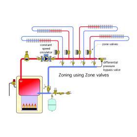
Another method of constructing multi-zone systems uses a single circulator in combination with an electrically operated zone valve on each zone circuit, as shown in Figure 9-6. When any zone thermostat calls for heat, its associated zone valve opens. An end switch within the zone valve closes once the valve reaches its fully open position. This switch signals the circulator and boiler to operate. All zone circuits begin and end at headers.
The differential pressure bypass valve installed at the right end of the headers limits the increase in differential pressure created by a constant-speed circulator as the number of active zones decreases. Without this valve, the increase in differential pressure created by a constant-speed circulator may cause excessive flow velocity and noise in operating zone circuits.
Zone valve systems have the following characteristics:
• Each zone circuit receives the same supply water temperature.
• The combined flow rate of all operating zones must pass through whatever the headers connect to. To minimize interaction between zone circuits, headers, as well as the piping components connected to the headers, should provide low head loss. This is generally not a problem when cast iron boilers or other low-head-loss heat sources are used. However, heat sources with higher flow resistance need to be hydraulically separated from the headers using either closely spaced tees or a hydraulic separator.
• The total electrical power demand of a zone valve system at design load tends to be lower than an equivalent system using zone circulators.
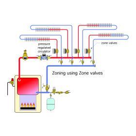
• Zone valve systems are well-suited to variable-speed pressure-regulated circulators that automatically adjust speed and electrical power input to maintain a constant differential pressure between the supply and return headers, regardless of which zone circuits are operating. When a pressure-regulated circulator is used, there is no need of a differential pressure bypass valve. Figure 9-7 shows the system of Figure 9-6 modified for use with a pressure-regulated circulator.
For a more in-depth discussion on Zone Valves:
SERIES PRIMARY/SECONDARY SYSTEMS
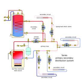
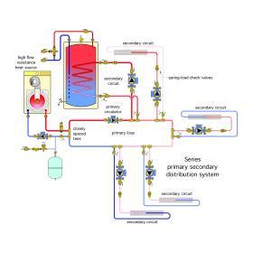
Series primary/secondary piping has been used for several decades in larger commercial hydronic systems. During the last two decades, this approach has also been adapted in multi-load/multitemperature residential hydronic systems within North America. A primary/secondary system usually consists of a single primary loop that delivers heated water to one or more secondary circuits. The latter are connected to the primary loop using pairs of closely spaced tees, as shown in Figures 9-8.
The pressure drop between a pair of closely spaced tees is almost zero. Thus, there is very little tendency for flow along the primary loop to induce flow within a secondary circuit. The closely spaced tees provide hydraulic separation between the primary circuit and each of the secondary circuits. Flow in a secondary circuit occurs when its own “secondary circulator” is turned on.
The word “series” describes how the sets of closely spaced tees are arranged, one set after another, along the primary loop.
If the heat source has low flow resistance, it is usually piped as part of the primary loop as shown in Figure 9-8. However, if the heat source has higher flow resistance, it is usually provided with its own circulator and connected to the primary loop using a set of closely spaced tees, as shown in Figure 9-9.
The following points summarize series primary/secondary systems:
• The sequential arrangement of secondary circuits around the primary loop creates a temperature drop wherever primary loop flow passes a pair of tees connected to an operating secondary circuit. As in series loops and diverter tee systems, this reduction in water temperature must be accounted for when sizing heat emitters.
• Each circuit in a primary/secondary system is hydraulically isolated from the other circuits. This prevents interference between circulators. Each circuit can be designed as if it’s a “stand-alone” circuit unaffected by other circuits in the system.
• A flow-check valve or spring-loaded check valve must be installed on the supply side of each secondary circuit to prevent buoyancy-driven heat migration.
• The primary circulator must operate whenever any one or more of the secondary circulators is operating. This increases electrical energy consumption relative to systems that do not require a primary circulator.
PARALLEL PRIMARY/SECONDARY SYSTEMS
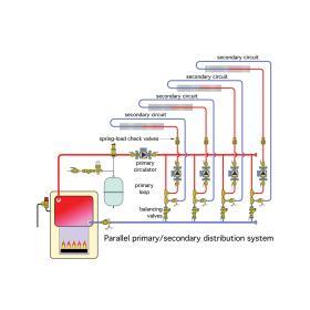
In a parallel primary/secondary system, the primary loop is divided into multiple parallel crossovers, as shown in Figure 9-10. Water from the heat source splits up through all these crossovers whenever the primary circulator is operating. A pair of closely spaced tees within each crossover provides hydraulic separation of each secondary circuit.
The following points summarize parallel primary/ secondary systems:
• The parallel arrangement of crossovers provides approximately the same water temperature to each secondary circuit. This simplifies heat emitter sizing.
• A balancing valve should be placed in each crossover so flow can be adjusted in proportion to the percentage of total load handled by the secondary circuit connected to each crossover. This adds to the installed cost and commissioning cost of the system.
• Each circuit in a parallel primary/ secondary system is hydraulically isolated from the other circuits. This prevents interference between circulators.
• A flow-check valve or spring-loaded check valve must be installed on the supply side of each secondary circuit to prevent buoyancy-driven heat migration.
• The primary circulator must operate whenever any one or more of the secondary circulators is operating. This increases the electrical energy consumption of the system relative to systems that do not require a primary circulator.
Although a parallel primary/ secondary system improves upon a series primary/secondary system by providing equal supply water temperatures to each secondary circuit, it does so with added complexity and expense.
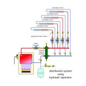
The benefits offered by a parallel primary/secondary system can be provided with simpler piping by using a hydraulic separator as shown in Figure 9-11. This system provides equivalent thermal and hydraulic performance to the system shown in Figure 9-10. High-performance air and dirt separation is also provided by the Caleffi HydroCal hydraulic separator.
MANIFOLD-TYPE DISTRIBUTION SYSTEMS
Polymer-based tubing, such as PEX, PEX-AL-PEX and PE-RT (polyethylene - raised temperature), has become increasingly popular worldwide as an alternative to rigid metal tubing. In North America, these flexible tubing materials are best known for their use in hydronic radiant panel heating systems. Beyond such applications, their temperature and pressure ratings, flexible characteristics and long continuous lengths make them well-suited to other types of hydronic distribution systems.
In North America, one or more of these flexible tubing materials is currently available in sizes from 5/16” to 2” nominal inside diameter. Of these, 3/8” to 3/4” are the most commonly used sizes for branch circuits in manifold-type distribution systems.
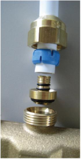
Special fittings are available for connecting both PEX and PEX-AL-PEX tubing to cast brass manifolds, as shown in Figure 9-12.
These fittings use a single, wrench-tightened mechanical compression nut and collar in combination with precision O-rings to ensure high-quality seals at both the tube and manifold connection. When selecting manifold connection fittings, be sure their temperature/pressure rating is compatible with the intended operating conditions.
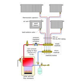
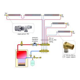
A simple manifold-based hydronic distribution system is shown in Figure 9-13.
The low-flow-resistance boiler supplies heated water to a single manifold station. The heated water enters the supply manifold and splits up among the various branch circuits based on their current needs. These branch circuits are piped with PEX or PEX-AL-PEX tubing. Each branch serves a single heat emitter—in this case, panel radiators equipped with thermostatic radiator valves. The common piping that connects the manifold station and boiler should be sized for a maximum flow velocity of 2 feet per second to minimize any tendency for flow in one branch circuit to affect flow in other branch circuits.
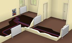
The manifold station can be installed within a wall cavity, as shown in Figure 9-14. It can also be installed under a floor deck or in the basement below the floor level(s) where the heat emitters are located.
Manifold-based distribution systems offer several advantages compared to distribution systems using rigid metal pipe.
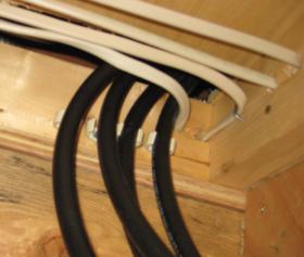
• The use of small-diameter flexible tubing allows for easy installation of individual circuits. This is especially important in retrofit installations where the installation of rigid piping often requires cutting through finished walls and ceilings. In many of these situations, it’s possible to pull small-diameter flexible tubing through confined spaces, much like flexible electrical cable can be “snaked” from one point to another within a building (see Figure 9-15).
• They supply water at approximately the same temperature to each heat emitter. Thus, heat emitters can all be selected based on the same design load supply water temperature. Each heat emitter also receives equal water temperature reduction in systems using outdoor reset control.
• Manifold systems, when combined with either thermostatic radiator valves or individual room thermostats, allow room-by-room temperature control. This allows each heat emitter to adjust its output to compensate for internal heat gains created by sunlight, people or equipment. It also allows each room to be adjusted for individual temperature preferences or unoccupied temperature setbacks.
• They allow a variety of heat emitters to be used in the same distribution system. Heat emitters such as fin-tube baseboard, panel radiators, fan-coils and towel warmers can all be combined into the same system, each on their own branch circuit, provided they are all sized to operate at the same supply water temperature at design load conditions.
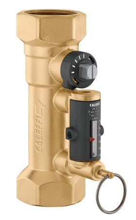
• The flow rate in each circuit can be adjusted independently using balancing valves built into the manifold station or valves attached to or integrated into each heat emitter. Flow adjustments can compensate for “overflow” in shorter circuits and prevent flow starvation in longer circuits.
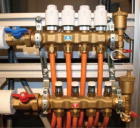
• The flow in each circuit can be turned on or off, or modulated. On/off flow control is done using manifold valve actuators. The upper (return) manifold shown in Figure 9-16 is equipped with 4 of these actuators.
Manifold valve actuators are powered by a 24 VAC thermostat circuit. When screwed into place over a manifold valve, they force the valve’s shaft to its closed position. When 24 VAC electrical power is supplied to the actuator, it retracts its stem and allows the spring-loaded manifold valve to open.
• Manifold distribution systems that use either on/ off or modulating flow control through each circuit are ideally suited to ECM-based pressure-regulated circulators. Figure 9-17 shows how fin-tube baseboard can be supplied using a manifold distribution system in combination with thermostatic radiator valves. This type of installation is faster, easier and often less expensive than installing fin-tube baseboard using soldered copper tubing.
• Adaptability to Variable-Speed Pressure-Regulated Circulators. All manifold systems that use valves to regulate flow through branch circuits need a means of differential pressure control. It can be provided by a differential pressure bypass valve or use of a pressure-regulated circulator. The latter scenario is becoming increasingly popular as new ECM (Electronically Commutated Motor) circulators become available in North America. Such circulators are ideal for manifold-type distribution systems. They automatically control differential pressure and significantly reduce electrical power consumption under partial-load conditions.
• Lower operating cost: The parallel branches of a manifold distribution system often create less total flow resistance than series or diverter tee-type distribution systems. This reduces the electrical power required to maintain circulation, both at design load conditions when all circuits are active, as well as during part-load conditions when some circuits are off and a variable-speed pressure-regulated circulator is used.
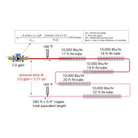
The system shown in Figure 9-18 is a typical series loop consisting of five baseboards. Each is sized to deliver 10,000 Btu/hr when the circuit is supplied with 180ºF water. The loop is constructed of 3/4” copper tubing and fittings. It’s assumed to follow the perimeter of a 30’ x 50’ house. With fittings factored in, this circuit has a total equivalent length of 280 feet. Delivering a total of 50,000 Btu/hr with an assumed temperature drop of 20ºF requires a flow rate of 5 gpm. Under these conditions, the pressure drop around the circuit is 5.51 psi. If this flow and differential pressure requirement is provided by a typical wet rotor circulator with a wire-to-water efficiency of 22%, the electrical wattage required to maintain circulation is 54.4 watts.
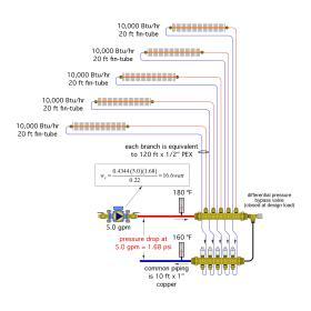
For comparison, Figure 9-19 shows a manifold distribution system designed to provide the same heating load. Each branch circuit consists of 1/2” PEX tubing and a 20-foot length of 3/4” fin-tube baseboard. The equivalent length of each branch circuit is assumed to be 120 feet of 1/2” PEX tubing. The manifold is supplied with 180ºF water through 1” copper tubing. At a flow rate of 5 gpm, this distribution system only develops a pressure drop of 1.68 psi. Assuming a circulator with the same 22% wire-towater efficiency was used, the electrical wattage required to maintain circulation would be 16.6 watts, less than one third that required by the series loop system.
If each distribution system operated 3,000 hours per year in a location where electrical energy costs 12 cents per kwhr, the annual electrical savings associated with the manifold system would be approximately $\$$13.60. If this cost inflated by 4% each year, the total savings over 20 years would be $405. This comparison is based on the nominal 22% peak wire-to-water efficiency of a constant speed PSCbased wet rotor circulator. Beyond this scenario is the possibility of using a variable-speed pressureregulated circulator for the manifold system. These circulators have demonstrated the ability to reduce electrical energy usage by 60% or more, relative to constant-speed, PSC-based wet rotor circulators.
For a more in-depth discussion on Zoning using Manifold valve actuators:
BASICS OF BALANCING
Many of the distribution systems discussed in this section use valves to regulate flow through two or more branch circuits. In most cases, the flow rates through these branch circuits need to be different due to differing heat delivery requirements.
The term “balancing” describes the process by which the flow rate in each branch of such systems is adjusted so that it is at or close to the flow required for proper heat delivery. Most hydronic heating professionals agree that balanced systems are desirable. However, opinions are widely varied on what constitutes a balanced system. The following are some of the common descriptions of a properly balanced system.
• The system is properly balanced if all simultaneously operating circuits have the same temperature drop.
• The system is properly balanced if the ratio of the flow rate through a branch circuit divided by the total system flow rate is the same as the ratio of the required heat output from that branch divided by the total system heat output.
• The system is properly balanced if all branch circuits are identically constructed (e.g., same type, size and length of tubing; same fittings and valves; same heat emitter).
• The system is properly balanced if constructed with a reverse return piping layout.
• The system is properly balanced if the installer doesn’t receive a complaint about some rooms being too hot while others are too cool.

