PREFACE
Previous sections have described the building blocks of modern hydronic systems. This section combines the principles and hardware discussed in previous sections into full systems.
Although there are virtually unlimited ways to combine design concepts and hardware into working systems, the designs presented in this section are focused on the most modern and cost-effective concepts. These designs are also built around common residential and light commercial building requirements.
SYSTEM #1
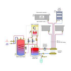
This system uses a mod/con boiler in combination with a manifold-based distribution system serving panel radiators and a towel warmer radiator. The heat output of each panel radiator and the towel warmer is regulated by a thermostatic radiator valve.
A 25-gallon Caleffi ThermoCon buffer tank interfaces the boiler to the distribution system. It provides hydraulic separation between the boiler circulator (P1) and the variable-speed pressure-regulated distribution circulator (P3). The thermal mass of this tank also helps prevent boiler short cycling when only one of the panel radiators is operating.
The boiler is operated by its internal outdoor reset controller. This controller monitors the temperature sensor installed in a well within the buffer tank whenever the system is “heating enabled.” The boiler operates as necessary to maintain the buffer tank at an appropriate temperature based on outdoor temperature. Thus, whenever the system is heating enabled, warm water is available to flow to any panel radiator with a partially open (or fully open) thermostatic valve.
The “heat-enabled” status of the system can be invoked several ways. One is to enable the system whenever the outdoor temperature drops below a preset value, such as 60ºF. Some boiler controllers provide this function. Another is to install a manually operated switch in the living space, and thus turn control over to the occupants. A third way is to enable heating using a “master thermostat” located within the living space. Whenever the indoor temperature drops slightly below the setting of this master thermostat, its contacts close to enable the system to begin heating operation.
In summary, this system takes advantage of modern concepts such as a high thermal efficiency mod/con boiler, low wattage pressure-regulated distribution circulator, outdoor reset control, small-diameter flexible distribution tubing, prioritized domestic water heating and “wireless” room-by-room zoning using thermostatic radiator valves.
For a more in-depth discussion on System #1:
SYSTEM #2
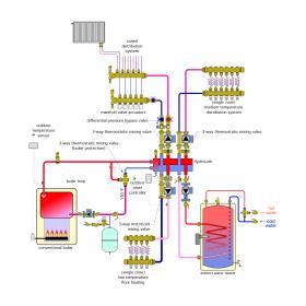
When a building contains multiple types of heat emitters, it is often necessary to create a distribution system that can simultaneously deliver multiple water temperatures. The schematic in Figure 11-2 is an example of such a system.
Heat is supplied by a conventional gas-fired boiler. As discussed in section 6, such boilers require protection from sustained flue gas condensation. This protection is provided by a high flow capacity thermostatic mixing valve (Caleffi 280). When the boiler undergoes a cold start, this valve recirculates water leaving the boiler’s outlet port, back to its inlet port. No hot water is allowed to pass farther into the distribution system. This allows the boiler to warm above the dewpoint temperature of its flue gases as soon as possible and remain above that dewpoint for the remainder of its operating cycle.
Once the boiler is operating at a temperature hot enough to prevent flue gas condensation, the thermostatic valve allows hot water to flow onward to the Caleffi HydroLink. This device combines a hydraulic separation chamber with two high flow capacity manifold chambers. All heating loads are supplied from and returned to the HydroLink. The hydraulic separation chamber on the left side of the HydroLink prevents the load circulators from interfering with each other.
The indirect domestic water heater is supplied directly from the HydroLink. Thus, it received water at or close to the temperature of the water leaving the boiler. Domestic water heating is treated as the priority load. The other three load circulators would not operate while domestic water heating is active. Also note that the circulator supplying the indirect water heater is equipped with an internal check valve to prevent reverse circulation when the water heating load is off, but other loads are on.
The three space heating subsystems each operate at different water temperatures. This schematic shows three possible mixing assemblies that could be used to create these temperatures. The panel radiators are supplied from a manifold station that is equipped with electric valve operators on each circuit. These operators allow flow through their respective circuits when energized with a 24 VAC electrical signal from associated thermostats.
Because different circuit valves will be open at different times, it is necessary to regulate differential pressure across the manifold. This is handled by a differential pressure bypass valve that is integrated into the mixing assembly (Caleffi 163 HydroMixer) attached to the HydroLink. The 163 HydroMixer also reduces the water temperature supplied to the manifold using an integrated thermostatic mixing valve.
The medium-temperature radiant panel circuits in the upper right corner of the schematic operate as a single zone. As such, no differential pressure regulation is necessary. Mixing is again handled by a Caleffi 163 HydroMixer, but without the differential pressure bypass subassembly.
The lower temperature radiant panel circuits in the lower left of the schematic also operate as a single zone. The mixed water temperature supplied to these circuits is created by a Caleffi 167 HydroMixer, which uses a motorized mixing valve and floating control actuator rather than a thermostatic mixing valve. This allows full reset of the supply water temperature based on the current outdoor temperature. It also allows the possibility of constant circulation through the radiant panel circuits, which is preferred by some designers. An outdoor reset controller that supplies a 3-wire floating output signal is used to operate the motorized actuator on the 167 HydroMixer.
For a more in-depth discussion on System #2:
SYSTEM #3
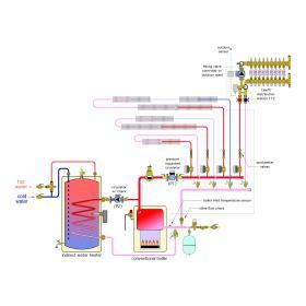
In residential applications, it’s common to see a conventional boiler supplying low-temperature floor heating to a basement slab, while also supplying higher temperature water to heat emitters, such as fin-tube baseboard, on the first and second floors. The need for domestic hot water rounds out the requirement. The system shown in Figure 11-3 provides a state-of-the-art solution.
This system contains 3 zones of fin-tube baseboard, each controlled by zone valve. The zones have differing amounts of baseboard, and thus likely need to operate at different flow rates. Each circuit is therefore equipped with a Caleffi 132 QuickSetter, which combines a flow meter with a balancing valve. These valves can be adjusted as necessary to achieve the required “design” flow rates in each circuit.
The low-temperature floor heating circuits in the basement are supplied by a Caleffi 172 distribution station. This station combines a motorized 3-way mixing valve, circulator, supply and return manifolds and a flow bypass connection that provides hydraulic separation between the circuit supplying hot water to the station and the circulator within the station. An outdoor reset controller with a floating output signal is used to control the motorized 3-way mixing valve. This controller also measures the water temperature entering the boiler, and if necessary, reduces hot water flow into the 3-way mixing valve to ensure the boiler does not operate with sustained flue gas condensation. Note the position of the boiler inlet temperature sensor. In this location, the sensor detects how all operating loads affect the boiler inlet temperature.
Flow to all space heating circuits is provided by a variable-speed pressure-regulated circulator that is set to maintain a constant differential pressure between the supply and return manifolds. As zone valves open up, this circulator automatically increases speed to maintain the fixed differential pressure, and vice versa.
Flow to the indirect water heater is provided by a fixed-speed circulator. If domestic water heating is to be a priority load, the space heating circulator (P1) is turned off during the domestic water heating cycle. If no load priority is used, circulators (P1) and (P2) can operate simultaneously. Either scenario is possible depending on the preferences of the designer and occupants.
The inline flow check valve on the return header prevents heat migration into that header. This is especially beneficial in warm weather, when domestic water heating is likely to be the only active load.
SYSTEM #4
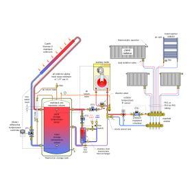
The benefits of hydronic systems can be merged with several types of renewable energy heat sources. One of the most common applications is to use an array of solar thermal collectors as the heat source for a system that provides both space heating and domestic hot water. Such systems are called “combisystems” and typically include an auxiliary heat source for times when the solar collector array cannot provide all the heat needed. The system in Figure 11-4 is an example of a solar thermal combisystem.
This system uses drainback freeze protection of the collector array. When the differential temperature controller senses that the collectors are a few degrees warmer than the water in the lower portion of the Caleffi ThermoCon storage tank, it turns on the collector circulator (P1). Water is driven up through the collector array, and air is pushed back down into the upper portion of the storage tank. Flow is sustained between the lower portion of the storage tank and the collector array, as long as the latter is a few degrees warmer than the lower storage tank. When this condition is no longer true, the collector circulator turns off and water in the collector array drains back to the storage tank. Air from the upper portion of the storage tank moves back into the collector array and associated piping. It is imperative that all piping between the collector array and storage tank be sloped a minimum of ¼ inch per foot to ensure complete drainage. All collector circuit piping should also be insulated to minimize heat loss, especially to unconditioned space.
The water temperature at the top of the storage tank is monitored by the auxiliary boiler. This boiler fires when necessary to maintain the upper portion of the storage tank at a temperature high enough to supply domestic water at the expected temperature. If solar input to the tank is sufficient to maintain this temperature, there is no need for the boiler to operate.
Domestic water is heated instantaneously whenever a hot water faucet is opened. When the domestic water flow rate reaches 0.5 gpm, the contacts of a flow detecting switch close. This completes an electrical circuit that allows the circulator (P3) to operate. Hot water from the top of the storage tank immediately flows through the left side of the stainless steel brazed plate heat exchanger, as cold domestic water flows into the right side of this heat exchanger. Heat is immediately transferred to the entering cold water, and it leaves the heat exchanger at a temperature high enough for delivery to the faucets. An ASSE 1017 thermostatic mixing valve with a maximum outlet temperature setting of 120ºF ensures that scalding hot water will not be delivered to the faucets in the event the storage tank is at a very high temperature. When the faucet is closed, the flow switch opens its contacts and circulator (P3) turns off.
When there is a demand for space heating, circulator (P2) operates to move hot water from the top of the storage tank through the diverting valve (from port AB to port B) and on to a pair of closely spaced tees. These tees provide hydraulic separation between circulator (P2) and circulator (P4). Hot water is drawn into the 3-way motorized mixing valve, which operates based on outdoor reset control to provide the required supply water temperature to the manifold-based distribution system. (P4) is a variable-speed pressure-regulated circulator that maintains a constant differential pressure across the manifold station that supplies each panel radiator. Flow through each radiator is managed by a thermostatic radiator valve.
As the storage tank temperature drops, the boiler fires and the diverter valve reroutes flow through the boiler (from port AB to port A). Boiler operation can be simultaneous with either space heating or domestic water heating, or it could occur when neither load is active, simply to maintain the tank at a suitable minimum temperature for domestic water heating. Circulator (P2) operates whenever the boiler is firing.
The thermal mass of the heated water in the storage tank provides excellent buffering of the zoned distribution system, and thus prevents the boiler from short cycling. This thermal mass also provides reserve capacity for domestic water heating. Any air captured by the vertical air separator is returned to the storage tank through the air return tube. This is an essential detail. It represents “air control” rather than “air elimination” and helps maintain the slight air pressurization within the system. If necessary, air can be added to the top of the storage tank to maintain this pressurization.
The captive air volume at the top of the tank also absorbs the expansion volume changes of the system’s water as its temperature varies. There is no need of a separate expansion tank. Also note that there is no automatic makeup water subassembly within this system. Instead, water can be added or removed through a drain valve at the bottom of the storage tank. The water level within the tank is monitored by a transparent sight tube seen at the left of the storage tank.
For a more in-depth discussion on System #4:
SYSTEM #5
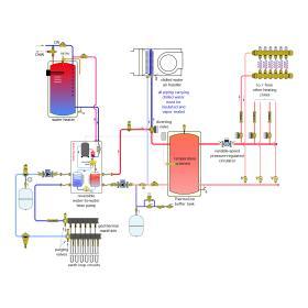
This system allows for multiple heating zones, along with a single zone of cooling. The latter is accomplished using an appropriately sized chilled water air handler equipped with a drip pan.
Whenever an on/off heat pump is used as the heat source for a zoned hydronic distribution system, a buffer tank must be used to prevent the heat pump from short cycling. The buffer tank stabilizes the system when the rate of heat generation by the heat pump is significantly different from the rate of heat dissipation by the zoned distribution system. The buffer tank also provides hydraulic separation between the circulator on the load side of the heat pump and the variable-speed circulator in the distribution system.
The size of the buffer tank depends on the acceptable minimum run time of the heat pump and the allowed temperature differential of the tank between when the heat pump turns on and when it turns off. Appendix B gives the necessary formulas for determining the size of the buffer tank.
The heat pump is turned on and off by an outdoor reset controller that monitors the temperature of the buffer tank whenever the system is in heating mode. Whenever the temperature of the storage tank drops below a calculated lower limit, the heat pump and its two associated circulators are turned on. When the tank reaches a calculated upper temperature limit, the heat pump and circulators are turned off.
Because the buffer tank is not active during the cooling mode, the total cooling capacity of the air handler must be matched to the cooling capacity of the heat pump at a chilled water supply temperature not lower than 45ºF. This will allow the air handler to provide good moisture removal from the air and prevent the heat pump from short-cycling.
The heat pump is also shown equipped with a desuperheater heat exchanger for preheating domestic water. Desuperheaters are an option offered by several manufacturers of water-to-water heat pumps. They are refrigerant-to-water heat exchangers that receive the highest temperature refrigerant gas directly from the compressor and transfer heat from that gas to a stream of domestic water being circulated through the desuperheater.
For a more in-depth discussion on System #5:
SYSTEM #6
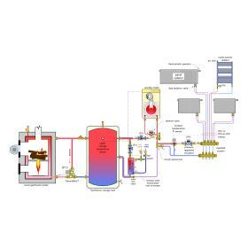
With the increasing cost of conventional fuels, boilers that burn firewood or wood pellets have become increasingly popular, especially in rural areas. Modern wood gasification boilers, when properly operated with dry wood, can yield thermal efficiencies approaching 90%. However, to attain such performance, they must operate at a high burn rate. In this mode, they often produce heat at rates significantly higher than the current space heating requirement of the building they serve. The solution is to install a thermal storage tank.
With the exception of some pellet-fired boilers, woodfired boilers cannot automatically start themselves. Thus, there will likely be times when heat is needed by the building, or perhaps for domestic hot water, and the wood-fired boiler is not operating. To accommodate these situations, many systems incorporate an auxiliary boiler that can automatically turn on to provide space heating and domestic water until the output of the woodfired boiler is sufficient to cover the load.
The system shown in Figure 11-6 provides a thermal storage tank, as well as an auxiliary boiler. From the ThermoCon storage tank out through the distribution system, this schematic is identical to the schematic in Figure 11-4. The only difference is that a wood gasification boiler serves as the primary heat source rather than an array of solar collectors.
The piping leading into wood gasification boiler is equipped with a Caleffi ThermoBloc anti-condensation device. This device combines a circulator and thermostatic mixing valve. It operates whenever the wood gasification boiler is operating and prevents the boiler from operating with sustained condensation of the flue gases it produces. This reduces the possibility of creosote formation within the boiler.
During a power failure, the ThermoBloc also allows thermosyphon flow between the storage tank and boiler. This flow dissipates residual heat that continues to be generated (albeit at a much lower rate) within the boiler. If the wood gasification boiler can maintain the thermal storage tank at a temperature sufficient to provide domestic hot water and space heating, the auxiliary boiler will not operate. If the tank temperature drops due to insufficient heat from the wood gasification boiler, the auxiliary boiler automatically fires to maintain a minimum accepted water temperature at the top of the storage tank.
For a more in-depth discussion on System #6:

