PREFACE
Water-based hydronic heating systems in North America date back over a century. Most accounts point to water-based systems evolving from steam-based systems. The latter were the first means of equipping buildings with “central” heating. Before that, heating was done with fireplaces and wood-fired or coal-fired stoves located throughout the building.
Although steam systems were effective, and some are still in use today, they impose several fundamental limitations on how the system must be designed and installed.
First, in a low-pressure steam heating system, the boiler needs to be located at the bottom of the distribution system. This is necessary to allow the condensate (steam that has cooled and changed back to liquid water) to flow back to the boiler.
Second, steam boilers generally need to operate at relatively high temperatures. There are exceptions to this (e.g., vacuum-based steam systems), but they are not common. The high temperatures needed to produce steam essentially eliminate contemporary heat source options such as solar thermal collectors or heat pumps.
Third, steam systems require carefully planned metal piping systems. The piping must be pitched for condensate return to the boiler. Fittings on steam mains must be properly oriented. The temperatures at which most steam heating systems operate preclude the use of polymer piping such as PEX or polypropylene. Pipe sizes also tend to be larger than those required for water-based distribution systems. The installation cost of the iron or steel piping required in steam systems has significantly increased over the last decade.
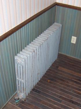
Most steam heating systems use cast iron radiators as their heat emitters. An example of such a radiator is shown in Figure 3-1. While such radiators can be very effective, and are often elegant in detail, they are very heavy. This significantly increases the cost of transportation and installation. The manufacturing procedures used for cast iron have also become more difficult to sustain, especially in North America, due to increasing energy cost and environmental regulations.
Finally, the iron and steel piping used in steam heating systems at various times contains steam, liquid water and air. The combination of water, oxygen from air and iron creates iron oxides within the piping and radiators. These oxides eventually form a sludge that reduces heat transfer in the radiators and must be periodically “blown down” from steam producing boilers.
Steam heating deserves distinct recognition within the evolution of North American heating systems. Thousands of innovative products have been produced to improve the performance of steam heating systems over several decades. Still, given the resources and installation details they require, the current worldwide costs of energy and the availability of many competing methods of heat generation and delivery, very few new steam heating systems are being installed. The present market for steam heating is almost entirely based on replacement of older steam boilers, radiators and related hardware. Water, in liquid form, is the future of hydronic heating.
EARLY WATER-BASED SYSTEMS
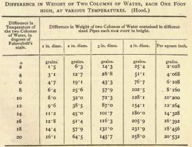
Water-based central heating systems were originally developed in the late 1800s. During that time, and for several decades to follow, there were no electrically powered circulators available. The only “propulsion effect” available to move water through systems was the differential pressure created by the simultaneous presence of hot and cool water. Hot water in the boiler is slightly lighter than cooler water in the return side piping. This creates a slight weight imbalance that causes hot water to rise while cool water descends, and thus circulation occurs within the system. Early designers quantified this effect, as shown in Figure 3-2, which dates from an 1896 heating manual.
These early hot water systems were often referred to as “gravity” hot water systems. An example of the piping used in these early hydronic systems is shown in Figure 3-3.
Notice that the piping is either vertical or slightly sloped. This slope encourages buoyancy driven flow and helps prevent air pockets from forming within the piping. Such pockets could block flow.
Many of these early systems contained an expansion tank at the high point in the system, often in the attic of a house. This tank was usually sized to 1/36th of the total system volume, and equipped with an overflow pipe leading to a drain or outside the building.
When heated, the water in the system expanded, possibly to the point where some would spill out of the overflow pipe from the expansion tank. As the system cooled, the water would decrease in volume, and the water level within the expansion tank would drop.
These early hydronic systems were open to the atmosphere at the overflow pipe. As such, the pressure within the boiler and piping were limited. In this respect, they were safer than pressurized steam systems of that vintage. However, due to evaporation, the water level within the system would slowly drop. Water had to be periodically added to maintain proper operation.
Although they took great advantage of natural principles to create circulation, these early systems were very limited in how they could be applied relative to modern hydronic systems.
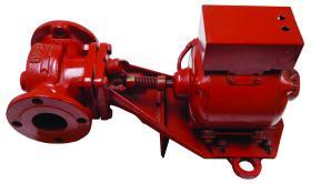
Many of these limitations were eliminated when electrically powered circulators became available in North America starting in the early 1930s. One example of an early generation (1931) “booster” circulator is shown in Figure 3-4.
Circulators could create much greater pressure differentials compared to those created solely by the buoyancy differences between hot and cool water. This allowed for smaller diameter piping that could go in virtually any direction. The boiler no longer had to be located at the base of the system. Piping layouts could be very different from those previously required. Response times were also significantly shorter than with natural circulation systems.
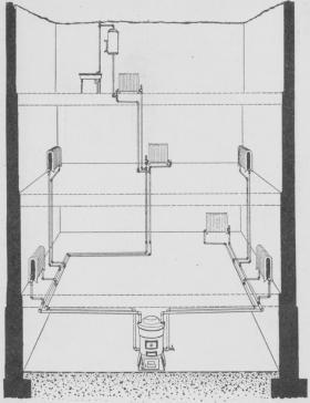
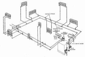
Figure 3-5 shows a 1949 drawing of a two-zone hydronic heating system using circulators. This system used a special fitting called a “Monoflo® tee” to induce flow from the distribution mains through each cast iron radiator. These fittings are still available, and their application is discussed in section 9.
Systems of this vintage were entirely constructed of steel or iron piping, typically with threaded cast iron fittings. As time progressed, copper tubing became an increasingly popular alternative, especially in residential systems.
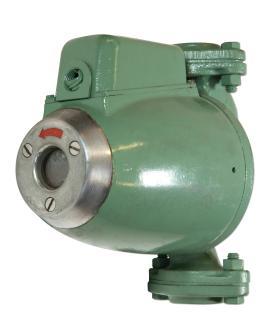
In 1958, Taco introduced the first “wet rotor” circulator to the North American hydronics market (shown in Figure 3-6).
Wet rotor circulators slowly gained acceptance as an alternative to traditional 3-piece circulators. By 1980, they had become the predominant type of circulator used in new residential and light commercial hydronic systems.
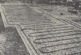
The availability of circulators also allowed for distribution systems and heat emitters very different from those required by “gravity” flow systems. One example is the hydronic radiant floor panel system shown in Figure 3-7, during its installation in the 1940s.
The first generation hydronic radiant panel systems used “grids” and “coils” of steel or wrought iron piping embedded in concrete slabs. After World War II, soft-temper copper tubing became the preferred material for such systems due to its availability in smaller sizes and easier bending characteristics. During the later 1940s and early 1950s, radiant floor and ceiling heating systems using copper tubing became increasingly popular.
Although these radiant panels delivered exceptional comfort for their time, and some are still in use today, others failed prematurely due to chemical reactions between copper tubing and certain materials used in concrete. Repetitive mechanical stresses due to the heating and cooling also caused some failures. Such issues eventually tarnished the reputation of hydronic radiant panel heating. By the 1970s, new installations of copper-based radiant panel heating systems were almost nonexistent.
Most residential hydronic systems of the 1960s through 1970s shifted to cast iron baseboard or copper fin-tube baseboard. Pressure-rated boilers with heat exchangers made of cast iron sections or steel fire tubes and fueled by natural gas and fuel oil became common. Hydronic systems of this era were relatively simple, typically having 1 to 3 zones and basic electromechanical controls. They were marketed as the modern, safe and fully automatic approach to centralized heating.
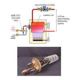
Some of the boilers used during this time were equipped with “tankless coil” water heaters, as shown in Figure 3-8. These devices allowed the boiler to provide domestic hot water as well as space heating. They also required the boiler to remain at an elevated temperature of at least 140ºF for the entire year. Although acceptable at the time, this method of domestic water heating is now viewed as very inefficient.
In the early 1980s, crosslinked polyethylene tubing (e.g., PEX) made its way to North America after several years of successful use in Europe. PEX, and other polymerbased tubing, revolutionized the installation of hydronic radiant panel heating, providing fast installation and a long, reliable life. The availability of PEX tubing was the spark that rekindled interest in hydronic radiant panel heating in North America during the 1980s. Since then, thousands of new products have been introduced into the North American hydronics market. These, in combination with contemporary design methods, ushered in the era of modern hydronics in North America
MODERN HYDRONICS
Today, much of the technology available for hydronic heating is a quantum leap above that available in the mid 1900s. Examples include the following:
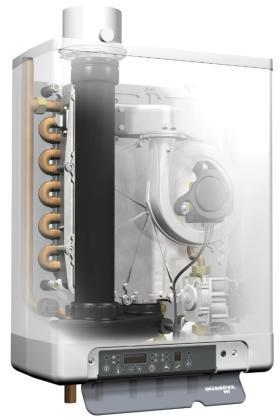
• Compact wall-hung condensing boilers, such as the one shown in Figure 3-9, when properly applied, can operate with thermal efficiencies in range of 95%.
In this and other issues of idronics, the word “density” refers to the number of pounds of the material needed to fill a volume of one cubic foot. For example, it would take 62.4 pounds of water at 50ºF to fill a 1 cubic foot container, so its density is said to be 62.4 pounds per cubic foot, (abbreviated as 62.4 lb/ft3 ).

