PREFACE
Nearly all hydronic systems have several common components. This section introduces those components and briefly describes their function. Later sections describe this hardware in more detail and show how to size and assemble it into complete systems.
The vast majority of modern hydronic heating systems are closed-loop systems. This means that the piping components form an assembly that separates the fluid within the system from contact with the atmosphere. If the system’s fluid is exposed to the atmosphere at any point, that system is classified as an open-loop system.
Closed-loop circuits have several advantages over “open-loop” systems.
First, because they are well-sealed from the atmosphere, there is very little fluid loss over time. Any slight fluid loss that occurs is usually attributable to weepage at valve packings or gaskets. Such minor losses do not create problems and can be automatically corrected with components discussed later in this section.
Second, properly designed closed-loop systems allow very little oxygen to enter the system. This greatly reduces the potential of corrosion, especially in systems containing iron or steel components.
Third, closed-loop systems operate under slight pressure. This helps in eliminating air from the system. It also helps in suppressing boiling or circulator noise within the system.
THE BASIC CLOSED CIRCUIT
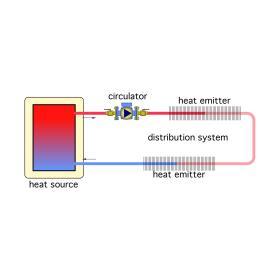
Figure 4-1 shows a basic closed-loop hydronic circuit. The box representing the heat source could be a boiler, a heat pump, a thermal storage tank heated by solar collectors or some other heat-producing device. Whatever the case, it is a closed device, sealed from the atmosphere and capable of operating under some pressure.
There are hydronic heat sources that are not closed. An example would be some outdoor wood-burning furnaces, which are not designed to operate under pressure.
The fluid within a hydronic circuit serves as a conveyor belt for heat. That heat is transferred into the fluid at the heat source, carried through the distribution system by the fluid and dissipated from the fluid at one or more heat emitters. The fluid then returns to the heat source to absorb more heat and repeat the process. A circulator, when operating, maintains flow through the system. The same fluid remains in the closed-loop system, often for many years. It never loses its ability to absorb, transport or dissipate heat.
BASIC CONTROLS
In an ideal system, the rate at which the heat source produces heat would always match the rate at which the building, or domestic water, needs heating. This is seldom the case with any real system, and thus it is necessary to provide controllers that manage both heat production and heat delivery.
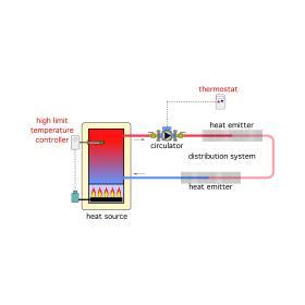
One of the most basic controllers is a thermostat that measures room air temperature and turns the circulator on and off based on how the room’s temperature compares to the thermostat’s setpoint. The thermostat’s “goal” is to keep the room air temperature at, or very close to, its setpoint temperature. If the room’s air temperature begins rising above the setpoint temperature, the thermostat turns off the circulator to stop further heat transport to the heat emitters. When the room temperature drops below the thermostat’s setpoint, it turns on the circulator to resume heat transport.
Another common controller is called a high-limit controller. Its function is to turn the heat source on and off so that the temperature of the fluid supplied to the distribution system remains within a narrow and usable range.
Figure 4-2 shows a basic hydronic system supplied by a fuel-burning heat source. The circulator is assumed to be controlled by a room thermostat. The water temperature supplied by the heat source is limited by the high-limit controller.
EXPANSION TANK
Water expands when it is heated. This is a very powerful but predictable characteristic that must be accommodated in any type of closed-loop hydronic system. Figure 4-3 shows a diaphragm-type expansion tank added to the system. This tank contains a captive volume of air. As the heated water within the system expands, it pushes into the tank and slightly compresses the captive air volume. This causes the system pressure to rise a small amount. As the system’s water cools, its volume decreases, allowing the compressed air to expand, and the system pressure returns to its original value. This process repeats itself each time the system heats up and cools off. Expansion tank selection and sizing are covered in section 6.
PRESSURE-RELIEF VALVE
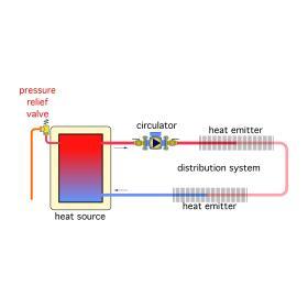
Consider what could happen to a closed-loop hydronic system in which a defective high-limit controller fails to turn off the heat source after its upper temperature limit has been reached. As the water gets hotter, system pressure steadily increases due to the water’s expansion. This pressure could eventually exceed the pressure rating of the weakest component in the system. The consequences of a system component bursting at high pressures and temperatures could be devastating. Thus, all closed-loop hydronic systems must be protected by a pressure-relief valve. This is a universal requirement of all mechanical codes in North America. Figure 4-4 shows a pressure relief valve installed on the heat source.
MAKE-UP WATER SYSTEM
Most closed-loop hydronic systems experience very minor water losses over time due to weepage from valve packings, pump seals, air vents and other components. These losses are normal and must be replaced to maintain adequate system pressure.
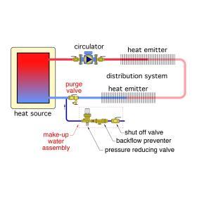
A common method for replacing this water is through an automatic make-up water assembly consisting of a pressure-reducing valve, backflow preventer and shutoff valve (shown in Figure 4-5).
Because the pressure in a building water system is usually higher than the pressure-relief valve setting in a hydronic system, the latter cannot be directly piped to the building water system. However, a pressure-reducing valve can be placed between the building water system and hydronic system to limit pressure in the latter. This valve is used to reduce and maintain a constant minimum pressure within the hydronic system. It lets water enter the hydronic system whenever the pressure in the system drops below the valve’s pressure setting. Most pressure reducing valves have an adjustable pressure setting.
The backflow preventer stops any water that has entered the system from returning and possibly contaminating the potable water supply system. Most municipal codes require such a device on any heating system connected to a public water supply.
The shutoff valve in the make-up water assembly is installed to allow the system to be isolated from its water source.
A purging valve is also shown in the schematic of Figure 4-5. It allows most of the air within the circuit to exit as the system is filled with water. Purging valves consist of a ball valve that is inline with the distribution piping and a side-mounted drain port. To purge the system, the inline ball valve is closed and the drain port is opened. As water enters the system through the make-up water assembly, air is expelled through the drain port of the purge valve.
AIR SEPARATOR
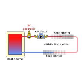
An air separator is designed to separate air from water and remove that air from the system. Modern air separators create regions of reduced pressure as water passes through. The lowered pressure causes dissolved gases in the water to form into bubbles. These bubbles are guided upward into a collection chamber where an automatic air vent expels them from the system. For best results, the air separator should be located where fluid temperatures are highest. This is typically in the supply pipe from the heat source, as shown in Figure 4-6.
For a more in-depth discussion on air separators:
PUTTING IT ALL TOGETHER
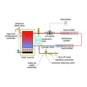
Figure 4-7 shows all the components previously discussed in their proper positions relative to each other. By assembling these components, we have built a simple hydronic heating system. However, just because all the components are present doesn’t guarantee that the system will function properly. The components must be selected and sized properly so that they work together as a system. Later sections will discuss how to do this.

