PREFACE
Although the heat source is a critical component in any hydronic heating system, it is useless without a variety of other “building block” components, such as pipe, fittings and valves. This section provides basic information on the latter. Later sections will provide basic information and several other building block components.
PIPING
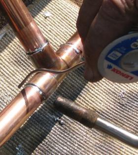
Early generation hydronic systems were piped with rigid steel and iron piping. Threaded fittings were used to join this piping in residential and light commercial systems. In large systems, the piping was usually joined by welding. These piping materials and joining systems were used largely because they were available at the time.
In North America, some steel and iron piping is still used. However, its use is typically limited to “near boiler” piping in the mechanical room. It is seldom used for distribution piping through the building.
After World War II, copper water tube gradually replaced iron and steel piping as the dominant piping material for smaller hydronic systems. In the United States, copper water tube is manufactured according to the ASTM B88 standard. In this category, pipe size refers to the nominal inside diameter of the tube. The word “nominal” means that the measured inside diameter is approximately equal to the stated pipe size. For example, the actual inside diameter of a 3/4” type M copper tube is 0.811 inches, not 0.750 inches as the stated pipe size might imply. The outside diameter of copper water tube is always 1/8 inch larger than the nominal inside diameter. For example, the outside diameter (O.D.) of 3/4” type M copper tube is 0.875 inches. This is exactly 7/8 inches, or 1/8 inch larger than the nominal pipe size.
Copper water tube is available in three wall thicknesses designated as types K, L and M in order of decreasing wall thickness. The outside diameters of K, L and M copper tubing are identical. This allows all three types of tubing to be used with the same fittings and valves.
Because the operating pressures of residential and light commercial hydronic heating systems are relatively low, the thinnest-wall copper tubing (type M) is most often used. This wall thickness provides several times the pressure rating of other common hydronic system components. Some codes may require the use of type L copper water tube for conveying domestic water. Type L tubing is also preferred if the tubing will be mechanically bent to provide changes in direction.
Copper tubing has relatively good resistance to corrosion that can result from carrying water containing dissolved oxygen. However, copper tubing is not immune from all corrosion. The acids formed by glycol-based antifreeze that have chemically degraded due to extreme temperatures can be aggressive toward copper. This type of corrosion can occur in solar thermal systems where collectors are allowed to repeatedly “stagnate” with no flow during times of high solar radiation intensity and high air temperatures. Copper tubing can also be corroded by water with high concentrations of hydrogen sulfide.
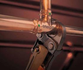
A newer method of joining copper tubing for hydronic system applications is called press fitting. This joining system uses special fittings containing elastomer (EPDM) O-rings that are mechanically compressed against the tube wall using a special tool. Figure 7-2 shows this pressing tool in use.
Advantages of press fit joints include:
• They can be made without cleaning or fluxing tube and fittings
• They can be made without flame from torches
• They can be made on fittings that is not completely dry
• They reduce installation time relative to soldered joints
The use of press fittings also has some limitations:
• Once made, press fit joints are permanent; they cannot be separated as soldered joints can.
• Press fitting requires special tools and fittings
• The O-rings used in press fittings have temperature and pressure limitations that are lower than those associated with soldered joints. However, some fittings are rated for operation at temperatures over 200ºF, and thus are well-suited for use in modern, lower temperature hydronic heating systems.
PEX TUBING
Crosslinked polyethylene tubing, commonly referred to as PEX, is a product that is now used worldwide for a variety of hydronic heating applications. It is best known for its use in hydronic radiant panel heating systems.
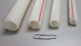
PEX has significantly higher pressure/temperature ratings than standard high density polyethylene (HDPE) tubing. In North America, most PEX tubing used in hydronic systems conforms to the ASTM F876 standard. It is commonly available in continuous rolls up through 1,000 feet, and in nominal pipe sizes from 5/16” through 2”. Tube sizes of 3/8” through 3/4” are commonly used in radiant panels. Large sizes are used for distribution piping. Figure 7-3 shows samples of PEX tubing in sizes of 3/8”, 1/2”, 5/8” and 3/4”.
With all plastic tubing, there is a tradeoff between operating temperature and allowable pressure. The ASTM F876 standard establishes three simultaneous temperature/pressure ratings for PEX tubing. The higher ratings for continuous operation are 180ºF at 100 psi and 200ºF at 80 psi.
Specialized fittings are available from the tubing manufacturers to transition from PEX tubing to standard metal pipe fittings, both threaded and soldered.
All polymer tubes allow diffusion of oxygen molecules from the outside of the tube to the fluid within them. When PEX tubing is used in closed-loop hydronic systems that contain any iron or steel components, the tubing should be specified with an oxygen diffusion barrier. This barrier is a thin layer of a special chemical that is either laminated to the outer surface of the tubing or co-extruded as an embedded layer. Its purpose is to reduce the diffusion of oxygen molecules through the tube wall, and thus significantly reduce the potential for oxygen-based corrosion within the system. All oxygen diffusion barriers on polymer tubing used for hydronic system applications should meet or exceed the requirements of the DIN 4726 standard.
PEX-AL-PEX TUBING
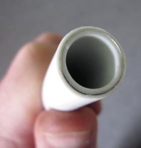
Another type of tubing well-suited for hydronic heating systems is called PEX-AL-PEX, (a.k.a. “composite” tubing). It consists of three concentric layers bonded together with special adhesives. The inner and outer layers are PEX. The middle layer is longitudinally welded aluminum. A close-up of the cut edge of a PEX-AL-PEX tube is shown in Figure 7-4. The aluminum layer is easy to see between the inner and outer layers of PEX.
The PEX-AL-PEX tubing commonly used in hydronic heating systems conforms to the ASTM F1281 standard. This tubing has slightly higher temperature pressure ratings compared to PEX. This is attributable to the added strength of the aluminum layer. At 180ºF, ASTM F1281 PEX-AL-PEX tubing is rated for pressures up to 125 psi. At 210ºF, it is rated for pressures up to 115 psi.
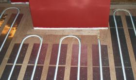
The aluminum layer in PEX-AL-PEX tubing also significantly reduces the expansion movement relative to other (all-polymer) tubes. This characteristic makes PEXAL-PEX well-suited for use in radiant panel construction where aluminum heat transfer plates are used as shown in Figure 7-5.
A wide variety of fittings are available for connecting PEXAL-PEX tubing to itself as well as copper tubing and other components.
OTHER POLYMER TUBING
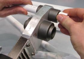
Two other types of polymer tubing are being increasingly used in modern hydronic systems. They are PE-RT and PP-R. PE-RT stands for PolyEthylene Raised Temperature. Although relatively new in North America, PE-RT tubing has been used for over 20 years in Europe. It provides pressure/temperature ratings of 200 psi at 73ºF and 100 psi at 180ºF. PE-RT tubing is available with an oxygen diffusion barrier for closed hydronic systems. It is also available with an aluminum core (e.g., PE-RT/AL/PE-RT). Like PEX, it can be joined with mechanical fittings. Because it is not crosslinked, it can also be permanently joined using socket fusion as shown in Figure 7-6.
Another polymer tubing that is relatively new to North American is Reinforced Polypropylene (PP-R). Available in sizes from 3/8” to 10”, PP-R tubing features a fiberglass-reinforced core that, in combination with the polypropylene inner and outer layers, limits thermal expansion and allows sustained operating temperatures up to 160ºF with a corresponding pressure of 70 psi and temporary operating temperatures up to 195ºF for 60 days.
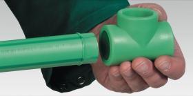
PP-R tubing is joined by either butt fusion or socket fusion (depending on size). Figure 7-7 shows the latter, where the molten end of the tube is about to be pushed into the molten socket of the fitting. A heating fixture similar to that shown in Figure 7-6 is used to simultaneously heat these surfaces on the tube and fitting to approximately 500ºF before joining. The resulting joint is permanent and extremely strong. PP-R tubing is available in both coils and straight lengths. The latter is commonly used in lieu of rigid metal pipe within mechanical rooms and distribution systems for both heating and cooling.
PIPE FITTINGS
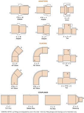
There are thousands of pipe fittings of various shapes, sizes and connections that can be used in hydronic systems. Figure 7-8 shows the more common types of fittings, in this case for copper tubing. Learning to specify the type of fitting needed is an important part of hydronic design and installation. Some of the common terminology, abbreviations and protocols for specifying fittings are as follows:
• Male pipe thread (MPT)
• Female pipe thread (FPT)
• Copper socket (C)
• For reducer fittings (with two different pipe sizes), specify the larger connection first
• For tees, specify the larger run connection, then the other run connection, and finally the side connection
COMMON VALVES
There are several common valves that are used in hydronic systems. They can be classified based on three basic purposes:
• Component isolation (the valve is typically fully open or fully closed)
• Flow regulation (the valve stem may be at any position as needed to limit flow rate)
• Preventing flow reversal
VALVES FOR COMPONENT ISOLATION
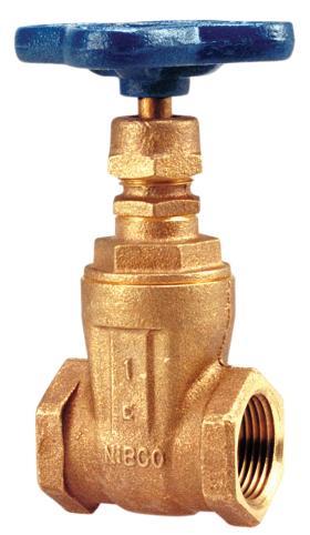
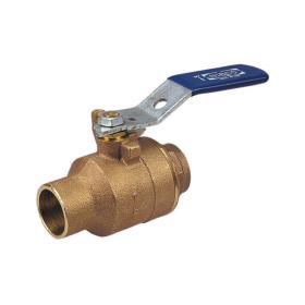
Figure 7-10 shows a full-port ball valve. Both gate valves and ball valves should be either fully open (when flow is allowed through them) or fully closed (to isolate a component from the remainder of the system). Operating either of these valves in a partially open mode can lead to chattering and eventual erosion of their internal trim or seals.
VALVES FOR FLOW REGULATION
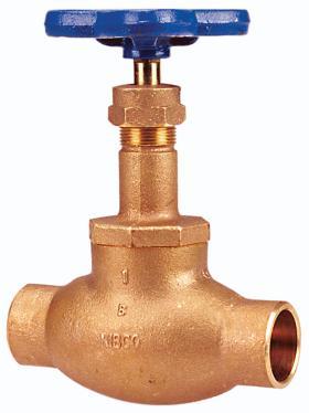
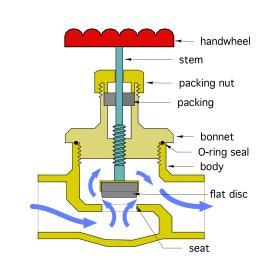
Globe valves force fluid to pass through a path having several abrupt changes in direction as shown in Figure 7-12. The fluid enters the lower valve chamber, flows upward through the gap between the seat and disc and then exits sideways from the upper chamber. This enables the valve to dissipate head energy from the fluid, and thus create a pressure drop. The stem controls the position of the disc above the seat. The closer the disc is to the seat, the greater the pressure drop across the valve.
Always install globe valves so the fluid flows into the lower body chamber and upward toward the disc. Reverse flow through a globe valve can cause unstable flow regulation, noise and cavitation. All globe valves have an arrow on their body that indicates the proper flow direction through the valve.
Globe valves should never be used for component isolation. Even in their fully open position, globe valves remove considerably more head energy from the fluid compared to a fully open gate valve or fully open ball valve. Therefore, during the thousands of operating hours when component isolation is not needed, the globe valve unnecessarily wastes pumping energy. Using a globe valve for component isolation is like driving a car with the brakes partially applied all the time.
Several variations of the fundamental globe valve have been developed for hydronic systems. They are called balancing valves and are used to regulate how much flow passes through various branches of hydronic systems.
For a more in-depth discussion on Balancing valves:
CHECK VALVES
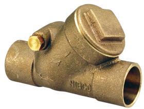
The term “check valve” applies to any valve intended to prevent flow reversal. Such valves are commonly used in many types of hydronic systems. The simplest check valve is known as a swing check, an example of which is shown in Figure 7-13.
Swing check valves contain a disc hinged along its upper edge. When fluid moves through the valve in the allowed direction (as indicated by an arrow on the side of the valve’s body), the disc swings up into a chamber and out of the fluid stream. The moving fluid holds it there. When flow stops or attempts to reverse itself, the disc swings down due to its weight and seals across the opening of the valve. The greater the back pressure, the tighter the seal.
Swing check valves should always be installed in horizontal piping with the bonnet of the valve in an upright position. Installation in other orientations can cause erratic operation, which can lead to dangerous water hammer effects. It is also important to install swing check valves with a minimum of 12 pipe diameters of straight pipe upstream of the valve. This allows turbulence created by upstream components to partially dissipate before the flow enters the valve. Failure to do so can cause the valve’s disk to rattle.
Another type of check valve is called a spring check valve. These valves rely on a small internal spring to close the valve’s disc whenever fluid is not moving in the intended direction. This allows a spring check valve to be installed in any orientation. The force required to compress the spring does, however, create slightly more pressure drop compared to a swing check. An example of a spring check valve is shown in Figure 7-14.
Always install check valves with the arrow on the body pointing in the direction of intended flow. As with swing check valves, install at least 12 diameters of straight pipe upstream of spring-load check valves.
SPECIALTY VALVES
Several types of valves have been developed for specific applications in hydronic heating and cooling systems. This section provides an overview of these valves. More detailed information on some of these valves can be found in other issues of idronics, as well as manufacturer’s literature.
FEED WATER VALVE
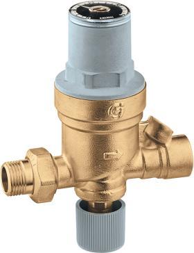
A feed water valve, which is also sometimes called a pressure-reducing valve, is used to lower the pressure of water from a domestic water distribution pipe before it enters a hydronic system. This valve is necessary because most buildings have domestic water pressure higher than the rated opening pressure of the relief valves used in hydronic systems. The feed water valve allows water to pass through whenever the pressure at its outlet side drops below its pressure setting. It allows small amounts of water to automatically enter the system as air is vented out. An example of a feed water valve is shown in Figure 7-15.
BACKFLOW PREVENTER
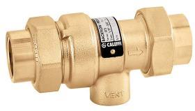
These valves are designed to prevent any water that has entered a hydronic heating system from flowing back out toward the potable water plumbing. This prevents potentially toxic liquids such as certain types of antifreeze from entering potable water piping. A backflow preventer consists of a pair of check valve assemblies in series, with an intermediate vent port that drains any backflow that migrates between the valve assemblies. An example of a small backflow preventer is shown in Figure 7-16.
A check valve, or even two check valves in series, are not acceptable substitutes for a backflow preventer. Such valves do not provide the vent port that would drain any minor amount of fluid passing through the downstream check assembly within a backflow preventer. Always be sure to install the backflow preventer with the arrow pointing into the hydronic system.
PRESSURE-RELIEF VALVE
A pressure-relief valve is a code requirement on any closed-loop hydronic heating system. It functions by opening at a preset pressure rating, allowing fluid to be safely released from the system before higher pressures can develop. The pressure-relief valve is the final means of protection in a situation where all other controls fail to limit heat production.
Most mechanical codes require pressure-relief valves in any piping assembly that contains a heat source and is capable of being isolated by valves from the rest of the system. A pressure-relief valve is also required in any piping circuit supplied with heat through a heat exchanger.
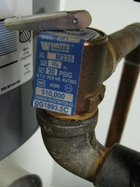
Pressure-relief valves contain a disc that is held against its seat by a spring. The spring is calibrated so that when the pressure on the inlet side of the valve reaches a certain level, the spring will allow the disc to lift off its seat and thus discharge fluid from the system. This rated opening pressure, along with the maximum heating capacity of the equipment the valve is rated to protect, is stamped onto a permanent tag or plate attached to the valve, as seen in Figure 7-17.
All pressure-relief valves should be installed with their shaft in a vertical position. This minimizes the chance of sediment accumulation around the valve’s disc. All pressure-relief valves should also have a waste pipe attached to their outlet port. This pipe routes any expelled fluid safely to a drain, or at least down near floor level. The waste pipe must be the same size as the valve’s outlet port with a minimal number of turns and no valves or other means of shutoff.
THERMOSTATIC RADIATOR VALVES
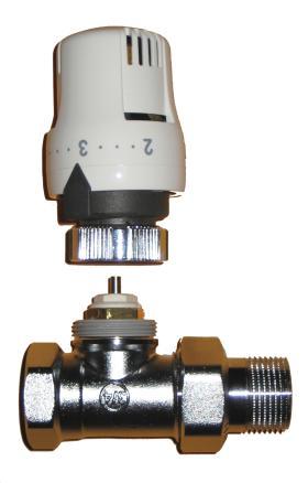
Thermostatic radiator valves (TRVs) can provide precise room-by-room temperature control in hydronic heating systems. They are installed in the supply pipe of a heat emitter, or in some cases integrated into the heat emitter. TRVs consist of two parts, the valve body and the thermostatic operator, as shown in Figure 7-18.
The nickel-plated brass valve body is available in either a straight pattern (as shown in Figure 7-18) or angle pattern. In the latter, the outlet port of the valve is rotated 90 degrees to the inlet port. Inside the valve is a plug mounted on a spring-loaded shaft. The plug is held in its fully open position by the force of the spring. The fluid pathway through the valve is similar to that of a globe valve, thus making the valve well-suited for flow control. To close the valve, the shaft must be pushed inward against the spring force. No rotation is necessary.
Shaft movement is provided by the thermostatic operator. This operator contains a fluid in a sealed bellows chamber. As the air temperature surrounding the operator increases, the fluid expands inside the bellows, which forces the shaft of the valve inward towards its closed position.
MIXING VALVES
Mixing valves are often used in hydronic heating systems to blend hot water from a heat source with cooler water returning from the distribution system. The goal of this blending is to achieve an appropriate supply water temperature to the distribution system, and thus produce the required heat output.
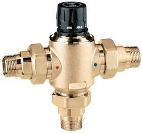
One of the most common types is called a 3-way mixing valve. It has three ports: one that allows hot water from the heat source to enter, another that allows cooler water from the return side of the distribution system to enter and a third port that supplies the mixture of the two entering flows to the distribution system.
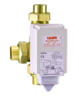
3-way mixing valves can be controlled by thermostatic actuators or motorized actuators. Figure 7-19 shows a 3-way mixing thermostatic mixing valve. The proportions of flow entering the ports of this valve are controlled by a non-electric actuator that is built into the valve.
Figure 7-20 shows a motorized 3-way mixing valve. The actuator attached to this valve is operated by a separate electronic controller. The actuator can rotate the stem of the valve to the position needed to achieve the desired supply water temperature to the system.
For a more in-depth discussion on Thermostatic and motorized mixing valves:
ZONE VALVES
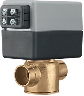
One of the previously discussed benefits of hydronic heating is the ability to easily configure the system to independently supply heat to multiple zones within a building. Zone valves are often used to allow or prevent flow through piping serving each of these zones. A typical electrically operated zone valve is shown in Figure 7-21. It consists of a valve body combined with an electrically powered actuator. The actuator is the device that produces movement of the valve shaft when supplied with an electrical signal.
Zone valves operate in either a fully open or a fully closed position. They do not modulate to regulate the flow rate in a piping circuit. Those with gear motor actuators, as shown in Figure 7-21, can move from fully closed to fully open in a few seconds.
For a more in-depth discussion on Zone valves:

