PREFACE
There are many types of hydronic heat emitters designed to extract heat from water flowing through them and release that heat into a space. These devices use a combination of convection and thermal radiation to release heat. Some are manufactured devices, while others are site-built and an integral part of the building they heat. This section discusses the most common hydronic heat emitters that are used in modern hydronic systems.
THERMAL EQUILIBRIUM
Before considering specific types of heat emitters, it’s important to understand a general principal that applies to every hydronic systems, regardless of the type of heat emitters used. That principle is call thermal equilibrium.
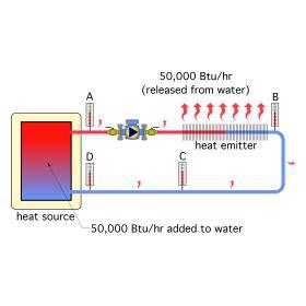
Consider the hydronic heating system shown in Figure 8-1.
In this system, the heat source is adding heat to the water passing through it at a rate of 50,000 Btu/hr. As the water flows through the distribution system, heat is being dissipated from it at the same rate of 50,000 Btu/hr. Under this condition, the system is in “thermal equilibrium,” and the water temperature at any given location in the circuit will remain steady.
The exact value of the water temperature at any of these locations will depend on the heat dissipating characteristics of the distribution system versus the heat generating capability of the heat source. For a given rate of heat generation, the higher the heat dissipating ability of the distribution system, the lower the water temperature will be at all locations around the circuit. Conversely, the lower the heat dissipating ability of the distribution system, the higher the water temperature will be at all locations.
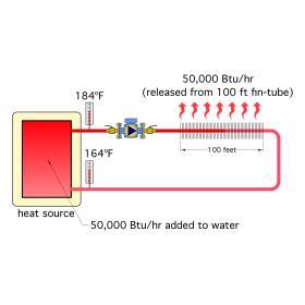
The system shown in Figure 8-2 contains 100 feet of typical residential-style fin-tube baseboard. For simplicity, assume all heat dissipation from the distribution system occurs at this baseboard. Assume the heat source is capable of generating water temperatures as high as 210ºF, and that the high-limit controller on the heat source is set for 200ºF. Initially, all system components and the water they contain are at room temperature.
The heat source and circulator are then turned on. The heat source is now adding heat to the water at the rate of 50,000 Btu/hr. The water temperature at all locations in the system continues to rise. However, the rate of this temperature rise slows as the water temperature leaving the heat source climbs higher and higher. When this temperature reaches 184ºF, there is no further rise, even though the boiler remains in continuous operation.
The explanation for this behavior is that when water at 184ºF is supplied to 100 feet of fin-tube baseboard, it can dissipate 50,000 Btu/hr, exactly the same rate of heat transfer as is occurring at the heat source. There is no reason for the water temperature to climb any higher. The water temperature at all other locations around the circuit will also remain stable at this point (albeit, at lower temperatures farther downstream). The fact that the highlimit controller on the heat source was set at 200ºF makes no difference.
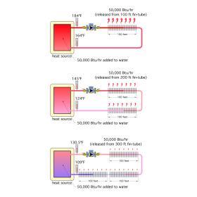
Now consider what would happen if this system were modified so that it contained 200 feet of the same baseboard. No other changes were made. When the system is turned on, the water temperature leaving the heat source rises until it stabilizes at 145ºF, as shown in Figure 8-3. At that point, the modified system has again reached thermal equilibrium, where the 50,000 Btu/hr rate of heat input at the heat source is exactly matched by the 50,000 Btu/hr heat dissipation rate from 200 feet of baseboard. Again, the fact that the high-limit controller on the heat source was set at 200ºF makes no difference.
Next, assume another 100 feet of baseboard was added to the system. When the system, which now contains 300 feet of baseboard, is turned on, the water temperature leaving the heat source stabilizes at 130.5ºF. It has again achieved thermal equilibrium, but at an even lower temperature. These scenarios show that increasing the heat dissipation capability of the distribution system lowers the supply water temperature at which thermal equilibrium occurs.
For a more in-depth discussion on Conventional Boilers:
In this case, the heat dissipation capability was increased by adding more heat emitter surface area. Other factors that could increase heat dissipation would include decreasing room air temperature, increasing water flow rate through the circuit or increasing the air velocity across the heat emitter surface. Lowering the water temperature at which thermal equilibrium occurs is generally acceptable, and even desirable, because it increases the thermal efficiency of most heat sources. However, “conventional” boilers have temperature limits below which they will experience sustained flue gas condensation. Operating a conventional boiler under such conditions is very undesirable because it causes corrosion of the boiler’s heat exchanger and vent piping. This limitation was discussed in more detail in section 6.If the heating capacity of the heat source is significantly higher than the heat dissipation ability of the distribution system, the temperature at which thermal equilibrium would occur is often much higher than the setting of the heat source’s high-limit controller.
For example, if the baseboard length in the system shown in Figure 8-2 was decreased to 50 feet, the water temperature leaving the heat source when thermal equilibrium was finally achieved would be about 265ºF. This is much higher than what is considered safe or efficient for any residential or light commercial system. Fortunately, the heat source’s high-limit controller would stop further heat generation when the outlet temperature reached 200ºF. The distribution circulator would remain on, and the water temperature leaving the heat source would decrease as heat continues to be dissipated by the distribution system. Eventually, the water temperature within the system would drop sufficiently to cause the heat source to turn back on, and the cycle would repeat itself. This is a very common operating mode in many systems during partial load conditions. It can even occur under design load conditions in systems having an oversized heat source.
In summary, every hydronic system “wants” to operate at thermal equilibrium. If not for the intervention of temperature-limiting controllers, the water temperature in any hydronic system will automatically adjust itself as necessary to make this occur. This water temperature may or may not provide the proper heat input to the building. Likewise, it may or may not be conducive to safe and efficient operation or long system life. Bluntly stated: The system “doesn’t care” if it’s delivering the proper amount of heat to the rooms or if it’s operating safely. It only “cares” about achieving a balance between heat input and heat output.
Good designers ensure that the heat source and heat emitters are properly matched so that thermal equilibrium occurs at water temperatures that are safe and allow for efficient operation of the heat source.
STANDARD FIN-TUBE BASEBOARD
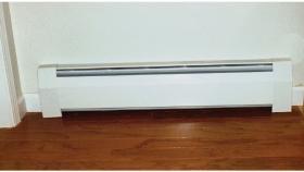
Perhaps the best known hydronic heat emitter in North America is standard fin-tube baseboard, an example of which is shown in Figure 8-4. Standard fin-tube baseboard was originally developed as an alternative to cast iron radiators. It consists of a copper tube with attached aluminum fins.
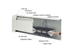
The purpose of the fins is to extend the surface area of the tube. The high conductivity of the aluminum fins “wicks” heat away from the copper tube, and transfers this heat to the air surrounding the fins. The warm air rises upward due to its lowered density. Cooler air near floor level flows inward and upward into the fin-tube element. This creates a gentle flow of warm air out of the slot at the top of the baseboard’s steel enclosure. A cut-away view of a typical fin-tube baseboard is shown in Figure 8-5.
Fin-tube baseboard is typically sold in straight lengths ranging from 2 to 8 feet in 1-foot increments. The finned tube element is a few inches shorter than the enclosure. Sheet metal accessories such as end caps, corners and straight enclosure splices are available to connect and trim the straight lengths.
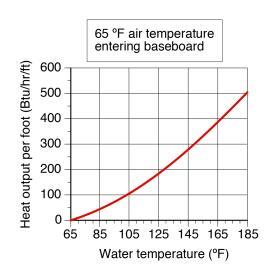
Figure 8-6 shows a typical heat output versus water temperature relationship for residential grade fin-tube baseboard. Designers should keep in mind that standard fin-tube baseboard was designed to operate at relatively high average water temperatures (160ºF to 200ºF). While such temperatures are available from conventional boilers, they are well above what most renewable energy heat sources such as solar thermal collectors and heat pumps can provide. These high water temperatures also lower the efficiency of mod/con boilers.
For a more in-depth discussion on Standard fin-tube base boards:
LOW-TEMPERATURE FIN-TUBE BASEBOARD
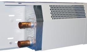
Low-temperature heat sources will be increasingly common in future hydronic systems. This has led to reconfigurations of traditional products in ways that allow them to operate at lower water temperatures. An example of one such product is the low-temperature fin-tube baseboard, shown in Figure 8-7.
This baseboard uses two tubes within its element (versus one tube in a standard baseboard element). The fin area is also approximately three times larger than that in standard fin-tube baseboard. This larger element allows a given rate of heat output at a significantly lower average water temperature.
For example, at an average water temperature of 110ºF, this baseboard releases about 290 Btu/hr/ft when the two pipes are configured for parallel flow, and the total flow rate through the element is 1 gpm (0.5 gpm through each tube). This increases to about 345 Btu/hr/ft with a total flow rate of 4 gpm (e.g., 2 gpm per tube). Typical residential fin-tube would need an average water temperature of about 152ºF (at 4 gpm flow rate) to yield the same output.
Low-temperature baseboard is well-suited to systems that use renewable heat sources such as solar thermal collectors or heat pumps. It also allows mod/con boilers to operate a very high thermal efficiency.
PANEL RADIATORS
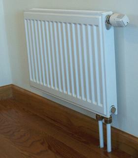
Modern panel radiators come in a wide range of shapes and sizes. Most are constructed of steel, while some are constructed of aluminum. An example of a typical steel panel radiator is shown in Figure 8-8.This panel radiator delivers radiant heating from the surfaces exposed to the room, as well as convective heating as room air is heated by fins concealed behind the front panel. Water is supplied to and carried away from the panel through the small-diameter tubes seen Panel radiators are available in different heights, widths and thicknesses.
The larger the surface area of the panel radiator, the higher its heat output will be for a given average water temperature and room air temperature. Panel thickness is increased by adding water plates to the radiator. The radiator shown in Figure 8-8 has a single water plate (e.g., the front of the panel with the vertical water channels running between the upper and lower headers). A double water plate radiator has two water plates arranged back-to-back.
A three-water plate panel adds one more water plate to the back of a double water plate panel. Multiple-water plate radiators are thicker, but this may be an acceptable tradeoff to keep the height of the panel low or reduce the required length of the panel. By using combinations of height, width and thickness, designers are able to specify radiators that can fit within locations with limited wall space, yet still provide adequate heat output.
Panel radiators are available in different heights, widths and thicknesses. The larger the surface area of the panel radiator, the higher its heat output will be for a given average water temperature and room air temperature. Panel thickness is increased by adding water plates to the radiator. The radiator shown in Figure 8-8 has a single water plate (e.g., the front of the panel with the vertical water channels running between the upper and lower headers). A double water plate radiator has two water plates arranged back-to-back. A three-water plate panel adds one more water plate to the back of a double water plate panel. Multiple-water plate radiators are thicker, but this may be an acceptable tradeoff to keep the height of the panel low or reduce the required length of the panel. By using combinations of height, width and thickness, designers are able to specify radiators that can fit within locations with limited wall space, yet still provide adequate heat output.
Manufacturers provide heat output ratings for their panel radiators in either graphical or tabular form. In many cases, “reference” heat output ratings are stated along with corresponding average water temperature and room air temperatures.
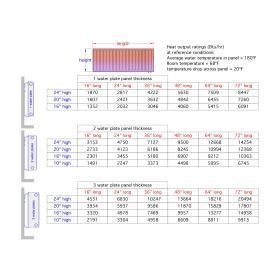
Figure 8-9 shows a heat output table for steel panel radiators of several different heights, widths and thicknesses.
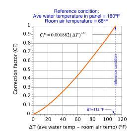
The heat outputs shown in Figure 8-9 are referenced to an average water temperature of 180ºF and a room air temperature of 68ºF. If different operating conditions are expected or desired, it’s necessary to multiply these reference heat output ratings by a correction factor. That factor can be determined from either the graph or formula shown in Figure 8-10.
Example: Find the output of a 24” high by 72” long single water plate panel if operated at an average water temperature of 110ºF in a room maintained at 68ºF.
Solution: Figure 8-9 indicates that a panel with a single water plate measuring 24” high and 72” long has a heat output of 8,447 Btu/hr based on the reference conditions of 180ºF average water temperature and 68ºF room air temperature. Using the formula in Figure 8-10, the correction factor with an average panel water temperature of 110ºF and room temperature of 68ºF is:
$$ CF = 0.001882(110-68)^{1.33}=0.271 $$
The estimated heat output at the lower water temperature is therefore:
$$ Output = (0.271) \times 8447 = 2289 \ Btu / hr $$
HYDRONIC FAN-COILS & AIR HANDLERS
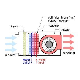
Another method of delivering heat to a building is through use of hydronic fan-coils and air handlers. These heat emitters receive heat from a hydronic distribution system, but deliver that heat to the room using forced air. A blower or fan within the unit creates the airflow. The forced air stream moves across a “coil” consisting of copper tubing with closely spaced aluminum fins. Figure 8-12 shows the typical construction of an air handler.
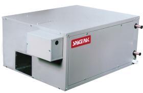
The term air handler describes a larger device that is usually designed for mounting in concealed spaces. Air handlers have larger coils and blowers contained within a vertical or horizontal sheet metal cabinet. They deliver an air stream to ducting that often distributes that air flow to more than one room. An example of a horizontal air handler is shown in Figure 8-14.
Some air handlers are also capable of delivering cooling when their coil is supplied with chilled water. This type of air handler must be equipped with a condensate drip pan located under its coil. The drip pan collects water droplets that form on the coil as it dehumidifies the warm/moist air passing through it. The drip pan connects to a pipe that routes the condensate to a suitable drain.
The thermal performance of hydronic fan coils is typically listed in a table for each specific model. The parameters that determine thermal performance include:
• Entering water temperature
• Entering air temperature
• Water flow rate through coil
• Air flow rate across coil
The following general guidelines hold true for more hydronic fan-coils and air handlers:
1. The heat output of a fan-coil or air handler is proportional to the temperature difference between the entering air and entering water.
Thus, if the heat output of a particular air handler was 10,000 Btu/hr when the entering air temperature was 65ºF and the entering water temperature was 140ºF, its output when supplied with 180ºF water could be estimated by the following proportion:
$$ \text{estimated heat output} = 10,000 \times \left( {180-65} \over {140-65} \right) =15,333 \ Btu/hr $$
2. Increasing either the water flow rate or air flow rate through the coil beyond the minimums stated by the manufacturer will marginally increase heat output.
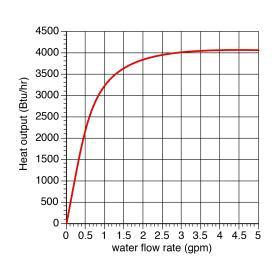
The effect of changing the water flow through the coil of a small fan-coil unit above or below the heat output rating established at a flow rate of 1 gpm is shown in Figure 8-15. At flow rates above 1 gpm the increase in heat output is slight. However, at flow rates below the rated 1 gpm, heat output decreases quickly
3. Air handlers or fan-coils with larger coils surfaces and/ or multiple tube passes through the coil are capable of delivering a rated heat output at lower entering water temperatures.
This relationship suggests that larger coils are preferred when the heat source is a mod/con boiler, solar thermal collector or heat pump. Fan coil units that operate at lower supply water temperatures should be located so that their discharge air stream does not directly impinge on room occupants. Although the temperature of the discharge air is warmer than the room air temperature, its velocity tends to make it feel cooler and may induce drafts of room air which cause discomfort. Registers or ceiling diffusers supplied by air handlers operating with lower temperature water should be selected and placed so that the air they discharge is well-mixed with room air.
RADIANT PANEL HEATING
Radiant heating is the process of transferring thermal energy from one object to another by thermal radiation. Whenever two surfaces are “within sight of each other,” and are at different temperatures, thermal radiation travels from the warmer surface to the cooler surface. All thermal radiation emitted by surfaces at temperatures lower than approximately 970ºF will be in the infrared portion of the electromagnetic spectrum, and as such cannot be seen by the human eye. All radiant panels discussed in this and other issues of idronics operate well below this temperature.
The thermal radiation emitted by a heated surface passes through room air with virtual no absorption of energy. Instead, the radiation is absorbed by the objects in the room. Most interior surfaces absorb the majority of any thermal radiation that strikes them. The small remaining portion is reflected, often to another surface where further absorption takes place.
It is thus accurate to state that thermal radiation (more commonly referred to as “radiant heat”) warms the objects in a room rather than directly heating the air. This difference is largely what separates radiant heating from convective heating. Because the absorbed thermal radiation raises the surface temperature of an object above the room air temperature, some heat will in turn be convected to room air.
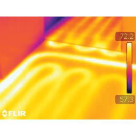
Although human eyes cannot see thermal radiation, it can be detected by specialized thermographic cameras. These devices determine the wavelength of thermal radiation (and thus the surface temperature) being detected by each pixel of their imaging system. They then associate a color with this temperature and display a thermographic image along with the associated color/ temperature scale. Figure 8-16 shows a thermographic image of a heated floor slab with tubing embedded about 2 inches below its surface.
It is important to understand that the thermal radiation emitter by a typical radiant panel is in no way unhealthy or harmful. Thermal radiation is constantly emitted from our skin and clothing surfaces to any cooler surfaces around us. This radiant heat emission is one of the ways our bodies dissipate the heat produced by metabolism.
The term hydronic radiant panel applies to any room surface (floor, wall or ceiling) that is heated or cooled by embedded tubing, and which has at least 50% of its heat output by thermal radiation. This section briefly discusses the more common types of hydronic radiant panels used for heating.
HEATED FLOOR SLABS
Concrete slab floors with embedded tubing are by far the most common type of hydronic radiant panel. They are also one of the most economical, because the concrete, and often the underslab insulation, is already specified as part of the building.
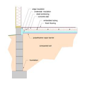
Figure 8-17 shows a cross-section for a heated floor slab. Notice that the tubing has been placed at approximately mid-depth within the slab, and that the underside and edge of the slab are well-insulated (R-10 ºF•hr•ft2 /Btu minimum). Both of these details are imperative in achieving good low-temperature performance.
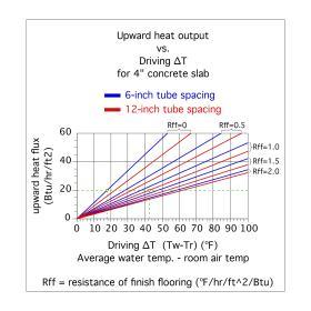
The graph in Figure 8-18 shows upward heat output from a heated slab based on tube spacing of 6”and 12”, and for finish floor resistances ranging from 0 to 2.0 (ºF•hr•ft2 /Btu). The steeper the line, the lower the water temperature required for a specific rate of heat delivery.
For example, achieving an upward heat output of 20 Btu/hr/ft2 from a slab with no covering (e.g., Rff = 0) and 6” tube spacing requires the “driving ∆T” (e.g., the difference between average water temperature in tubing and room air temperature) to be 17.5ºF. Thus, in a room maintained at 70ºF, the average water temperature in the circuit needs to be 87.5ºF. The supply water temperature to the circuit would likely be in the range of 95 ºF to 98ºF. This is a relatively low supply water temperature and would allow heat sources such as mod/con boilers, solar thermal collectors and heat pumps to operate at high thermal efficiency.
For comparison, consider supplying the same 20 Btu/hr/ft2 load using a heated floor slab with 12” tube spacing and a finish floor resistance of 1.0ºF•hr•ft2 /Btu. The driving ∆T must now be 42.5ºF. The average circuit water temperature required to maintain a room temperature of 70ºF would be 70 + 42.5 = 112.5ºF, and the supply temperature would be likely in the range of 120ºF to 123ºF. This higher temperature could be produced by conventional boilers but would lower the thermal efficiency of mod/con boilers, as well as solar collectors and heat pumps.
The following guidelines are suggested in applications where a heated floor slab will be used to deliver heat derived from a mod/con boiler or renewable energy heat source:
• Tube spacing within the slab should not exceed 12”.
• Slab should have minimum of R-10 underside and edge insulation.
• Tubing should be placed at approximately half the slab depth below the surface, as shown in Figure 8-17. Doing so decreases the required water temperature required for a given rate of heat output. Lower water temperatures improve heat source efficiency.
• Bare, painted or stained slab surfaces are ideal because the finish floor resistance is essentially zero.
• Other floor finishes should have a total R-value of 1.0 or less.
HEATED THIN SLABS
Another common method of installing floor heating uses a “thin slab” (1-1/2” to 2” thickness) poured over a wooden floor deck.
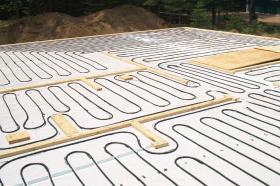
Figure 8-19 shows an example of such an installation awaiting placement of the concrete.
A concrete thin-slab installation begins by marking the location of all interior and exterior walls on the completed floor deck. The deck is then covered with 6-mill translucent polyethylene sheeting. This acts as a bond breaker layer between the wooden floor deck, and the concrete slab. It reduces shrinkage cracking of the concrete. The next step is to install 2x4 or 2x6 lumber where ever there is an interior partition or exterior wall. This lumber establishes the thickness of the thin slab.
The tubing is then fastened in place using a specialized pneumatic stapler. Once all tubing circuits are installed and connected to their associated manifold, they are pressure-tested with compressed air to verify that there are no leaks. Control joint strips are added where required. These details have all been completed in the photo shown in Figure 8-19. The final step is to place the concrete and screed it level with the top of the 2x4 or 2x6 lumber. The concrete is then troweled as with any other slab. Framing can usually resume the following day.
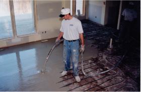
Thin-slabs can also be constructed using poured gypsum underlayment rather than concrete. The installation sequence differs from that used for a thin concrete slab. First, there is no bond breaker layer required. Second, the slab is typically poured after all walls have been installed and finished. The poured gypsum underlayment is mixed outside the building and pumped in through a hose. This material has a fluid consistency similar to pancake batter. As such it provides a high degree of self-leveling as it is poured on the floor, as seen in Figure 8-20.
ABOVE FLOOR TUBE & PLATE RADIANT PANELS
Although heated concrete floor slabs and thin-slabs make excellent radiant panels, they are not suitable for all installations. For example, in some cases, the floor structure cannot support the added dead loading of a thin-slab. In other cases, a nailed down hardwood finish floor cannot be properly fastened to a slab.
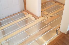
In such situations, designers have the option of using a tube & plate floor panel. These panels use aluminum plates as “wicks” to pull heat away from PEX or PEXAL-PEX tubing and disperse it across much of the floor area. The thin layer of highly conductive aluminum becomes the substitute for a much thicker and heavier layer of concrete.
Figure 8-21 shows an example of an above floor tube & plate radiant panel during construction. The installed tubing and aluminum plates will eventually be covered by a nailed-down hardwood finish floor. Adequate insulation must be installed under all above floor tube & plate radiant panels. If the space under the floor deck is heated or semi-heated, the insulation should have a minimum R-value of 19 ºF•hr•ft2 /Btu. If the space under the floor is unheated, the insulation should have a minimum R-value of 30 ºF•hr•ft2 /Btu.
Above floor tube & plate panels generally require higher water temperatures compared to slab systems for comparable heat output. Depending on the thermal resistance of the finish floor, average water temperatures of 120ºF to 140ºF are common under design load conditions.
BELOW FLOOR TUBE & PLATE RADIANT PANELS
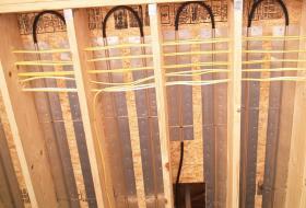
Tube & plate systems can also be installed on the bottom of a wood subfloor. Such a system is appropriately called a below floor tube & plate system. Figure 8-22 shows an example of such an installation, before installing the underfloor insulation.
Designers considering use of below floor tube & plate systems must consider possible interference with any existing or planned wiring, plumbing, ducting or structural details that may occupy the spaces between joists. In new installations, it is very important to have the tube and plates, and preferably the insulation, installed before other services that use the joist spaces are installed. Because of interference with wiring and plumbing, below floor tube & plate systems can be difficult to install in retrofit applications.
Below floor tube & plate systems must drive heat upward through the subfloor, as well as any finish flooring. This usually requires higher water temperatures relative to below floor tube & plates systems. Average water temperatures of 130ºF to 150ºF are common depending on the required rate of upward heat transfer and the thermal resistance of the finish flooring.
RADIANT WALL PANELS
Radiant panels can also be integrated into walls and ceilings. In some cases, wall or ceiling panels are preferable over floor panels. Examples include situations where finish flooring with high thermal resistance will be used or when a large percentage of the floor area will be covered with objects that inhibit upward heat flow.
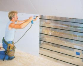
Figure 8-23 shows a radiant wall panel being constructed using ½” PEX-AL-PEX tubing and the same type of aluminum heat dispersion plates that are used for floor-based tube & plate systems.
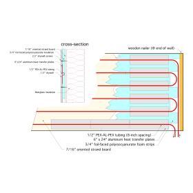
The construction details for this radiant wall panel are shown in Figure 8-24. When finished, this radiant wall panel is indistinguishable from a standard interior wall. Its low thermal mass allows it to respond quickly to changing internal load conditions or zone setback schedules. The rate of heat emission to the room is approximately 0.8 Btu/hr/ft2 for each degree Fahrenheit the average water temperature in the tubing exceeds room air temperature. Thus, if the wall operates with an average water temperature of 110ºF in a room with 70ºF air temperature, each square foot of wall would release about 0.8 x (110 - 70) = 32 Btu/hr/ft2 . This performance makes it well-suited for use with low-temperature hydronic heat sources.
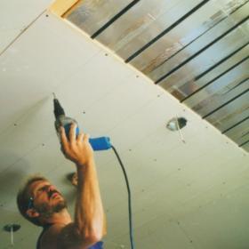
RADIANT CEILING PANELS
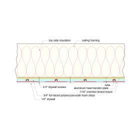
Figure 8-26 shows the construction details. As with the radiant wall, this radiant ceiling has low thermal mass and responds quickly to interior temperature changes. Heated ceilings also have the advantage of not being covered or blocked by coverings or furniture, and thus are likely to retain good performance over the life of the building.
For the construction shown in Figure 8-26, the rate of heat emission is approximately 0.71 Btu/hr/ft2 for each degree Fahrenheit the average water temperature in the tubing exceeds room air temperature. Thus, if the ceiling operated with an average water temperature of 110ºF in a room with 70ºF air temperature, each square foot of wall would release about 0.71 x (110 - 70) = 28.4 Btu/ hr/ft2 . This performance makes the radiant ceiling well-suited for use with low-temperature heat sources.

