PREFACE
One of the benefits of hydronic systems is that they can operate using a wide variety of heat sources. Almost any device that can heat water is a potential hydronic heat source. This section briefly discusses several hydronic heat sources that are commonly used in residential and light commercial systems.
CONVENTIONAL BOILERS
Boilers can be classified in many ways, such as by the fuel they use, heat output rating, construction material, heat exchanger geometry and methods for exhausting combustion gases. However, from the standpoint of system design, it is important to distinguish between “conventional” boilers and “condensing” boilers. Conventional boilers are intended to operate so that the water vapor produced during combustion does not condense on a sustained basis within the boiler or its venting system.
Nearly all boilers with cast iron, carbon steel or copper heat exchangers fall into this category. An example of a small gas-fired cast iron boiler is shown in Figure 6-1. Also shown is the schematic symbol used to represent any type of conventional boiler in this and other issues of idronics.
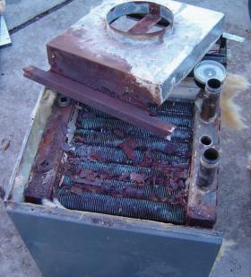
It’s important to understand that given the right operating conditions, ANY boiler can be forced to operate with sustained flue gas condensation. The condensate that can form is not pure water. It contains several chemical compounds based on the fuel burned and the efficiency at which combustion occurs. These compounds make the condensate highly corrosive. Materials such as cast iron, steel, copper and galvanized steel vent connector piping can rapidly corrode if repeatedly exposed to this condensate. The boiler heat exchanger shown in Figure 6-2 is evidence of such damage.
It is therefore imperative that conventional boilers are applied and operated so that sustained flue gas condensation does not occur. It’s also important to realize that all boilers experience intermittent flue gas condensation when starting from a cold condition. However, when a conventional boiler is properly applied, intermittent flue gas condensation quickly evaporates as the boiler warms. Intermittent flue gas condensation is not detrimental to the boiler.
The presence or absence of sustained flue gas condensation is determined by the temperature of the water entering the boiler, as well as the air/fuel ratio at which the combustion process occurs. Of these, only the boiler inlet water temperature is easily controllable by how the boiler is applied.
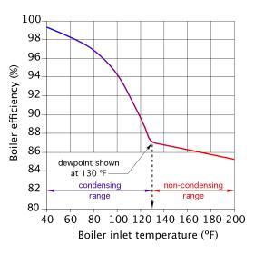
Figure 6-3 shows a typical relationship between the temperature of the water entering a boiler and that boiler’s associated thermal efficiency. The latter is the percentage of the chemical energy content of the fuel that is converted to heat and transferred to the water in the boiler’s heat exchanger. If the temperature of the water entering the boiler is relatively high (i.e., 200ºF), the combustion-side surfaces of the boiler’s heat exchanger are well above the dewpoint temperature of the water vapor in the exhaust gas stream. Under such conditions, no condensation occurs within the boiler.
However, as the temperature of the water entering the boiler decreases, so does the temperature of the boiler’s heat exchanger surfaces. At some entering water temperature, these surfaces reach the dewpoint temperature of the water vapor in the exhaust stream. This temperature varies with the type of fuel burned, as well as the air/fuel ratio supplied to the combustion chamber. For a conventional boiler operating with natural gas, the inlet water temperature at which condensation begins to form on the boiler’s heat exchanger is approximately 130ºF. The lower the entering water temperature, the more condensate that forms. In theory, if all the water vapor formed during combustion was condensed, approximately 1.15 gallons of liquid would be generated for each therm (e.g., 100,000 Btu) of natural gas burned.
For a more in-depth discussion on air separators:
CONDENSING BOILERS
Figure 6-3 shows that the thermal efficiency of a boiler increases rapidly when that boiler is operating in “condensing mode,” (e.g., with sustained flue gas condensation). The increased thermal efficiency comes from capturing the latent heat released as water vapor changes to liquid. Each pound of water vapor converted to liquid releases about 970 Btu of heat to the boiler’s heat exchanger. In a conventional boiler, this latent heat is carried away with the exhaust stream.
When fuel was inexpensive, there was little motivation to capture this latent heat. However, steadily increasing fuel costs have provided the incentive for boiler manufacturers to create boilers that are intended to operate with sustained flue gas condensation. Appropriately, they are called “condensing boilers.”
These boilers are constructed with large heat exchanger surfaces made of stainless steel or aluminum. These heat exchangers are capable of extracting more heat from the exhaust gases compared to the heat exchangers used in conventional boilers. When operated with suitably low inlet water temperatures, these boilers can easily cool the exhaust stream below the dewpoint temperature of the water vapor, and thus allow condensation to occur.
MODULATING/CONDENSING BOILERS
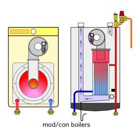
Early generation condensing boilers were built to operate at a fixed firing rate and thus a fixed rate of heat output. Today, nearly all condensing boilers can vary their heat output from some maximum rate down to approximately 20% of that maximum output. These boilers are said to be modulating. The term “mod/con” is often used to describe boilers that can vary their firing rates and are intended to operate with sustained flue gas condensation.
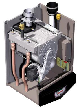
Figure 6-4 shows an example of a modern mod/con boiler, along with the schematic symbols used to represent mod/con boilers in this and other issues of idronics. Modulating the heat output of a boiler is similar to changing the throttle setting on an internal combustion engine. The rate of heat production is lowered by reducing the fuel and air sent to the burner. A variable-speed blower controls the air flow rate entering a sealed combustion chamber. Natural gas or propane is metered into this airstream in proportion to the air flow rate. The slightly pressurized mixture of gas and air is forced into a burner head and ignited. Burner heads are typically made of stainless steel or porous ceramic materials.
The ability of a mod/con boiler to modulate is expressed by its “turndown ratio.” This is the reciprocal of the lowest possible percentage of full heat output rate the boiler can maintain. For example: If a boiler can maintain stable operation down to 20% of its maximum heat output rate, it would have a turndown ratio of 5:1 (e.g., 5 being the reciprocal of 20% expressed as a decimal number).
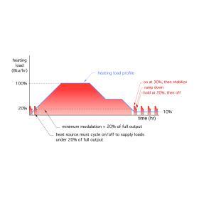
Figure 6-5 shows how the heat output of a modulating boiler with a turndown ratio of 5:1 matches its heat output to a hypothetical load. The blue line that borders the upper edge of the large shaded area is called a heating load profile. It represents the rate at which heat is required by the load over a period of several hours. The load begins at zero, steadily increases to a maximum value and then reduces in various slopes and plateaus over time, eventually stabilizing at 10% of maximum load.
The red-shaded areas represent the heat output from a mod/ con boiler. That boiler is assumed to have a turn down ratio of 5:1, and it is sized so that it exactly matches the maximum heating demand when it operates at 100% output. The pulses seen near the beginning and end of the load profile result from the boiler turning on at approximately 30% output, then quickly reducing output to the lower modulation limit of 20% and finally turning off for a short time. The large red-shaded area shows how the mod/con boiler accurately matches the load whenever it is 20% or more of the maximum load. This is ideal.
When loads drop below the minimum modulation rate (which in this case is 20%), the burner must cycle on and off to avoid oversupplying the load. When these on/off cycles occur frequently, they are known as “short cycling.” Such operation is always undesirable. It causes excessive wear on components such as the boiler’s ignition system. It also results in higher emissions and low thermal efficiency. Fortunately, short cycling can be avoided by proper system design and other components discussed later in this issue.
HEAT PUMPS
The low water temperatures at which some hydronic distribution systems can operate allows the possibility to use a heat pump as the system’s heat source. All heat pumps move heat from some material at a lower temperature (e.g., a temperature at which the material cannot directly supply heat to the load) to another material at a higher temperature. This is done using a refrigeration cycle.
The two types of heat pumps most often used in hydronic systems are:
• Water-to-water heat pumps
• Air-to-water heat pumps
Water-to-water heat pumps typically absorb low temperature heat from tubing buried in the earth or directly from ground water. Such heat pumps are further classified as “geothermal” heat pumps. They then deliver higher temperature water to a hydronic distribution system.
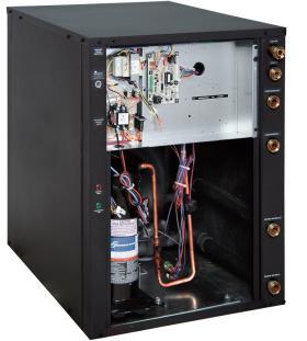
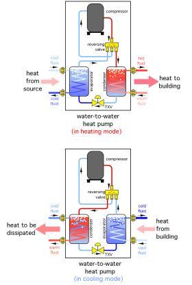
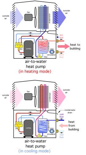
Figure 6-6 shows an example of a water-to-water heat pump, along with the schematic symbols used to represent it. Air-to-water heat pumps absorb low temperature heat directly from outside air. Then, as with water-to-water heat pumps, they deliver higher temperature water to a hydronic distribution system within the building.
Air-to-water heat pumps absorb low temperature heat directly from outside air. Then, as with water-to-water heat pumps, they deliver higher temperature water to a hydronic distribution system within the building.
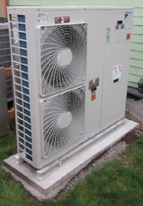
Figure 6-7 shows an example of an air-to-water heat pump mounted on a concrete base outside a house, along with the schematic symbols used to represent it.
A unique feature of both water-to-water and air-to-water heat pumps is that they can reverse the direction of heat movement. Thus, the same heat pump that supplies warm water for space heating in winter can also supply chilled water for space cooling in summer. This ability opens up a wide variety of applications.
For a more in-depth discussion on water-to-water and air-to-water heat pumps:
SOLAR THERMAL COLLECTORS
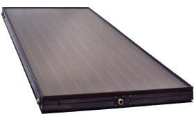
Significant increases in the price of conventional fuel combined with increased interest in environmental stewardship have created a growing market for thermally based use of solar energy. Solar thermal collectors, such as the one shown in Figure 6-8, can be easily integrated as a hydronic heating source in systems that supply both space heating and domestic hot water. Such systems are called solar “combisystems.”
Nearly all solar combisystems are equipped with “auxiliary” heating sources such as a boiler. Most of these systems are designed so that the auxiliary heat source will automatically operate to supply the heating load if the temperature of the thermal storage tank is insufficient to do so.
For a more in-depth discussion on Solar Thermal Collectors:
SOLID FUEL BOILERS
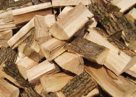
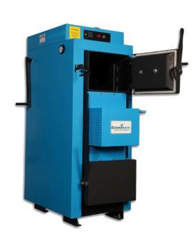
Several types of hydronic heat sources have been developed to burn cordwood. They include outdoor wood-fired furnaces and pressurized boilers. The latter can be further categorized as either atmospheric boilers or wood-gasification boilers. An example of the latter is shown in Figure 6-10.
When operated with properly dried (20% or lower moisture content) wood, gasification boilers can now produce combustion efficiencies approaching 90%. They also operate with much lower emissions compared to non-gasification wood-burning devices.
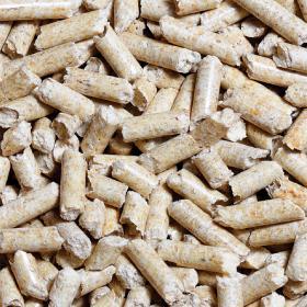
Pellets are another form of wood fuel. They are made by compressing dried wood fiber under very high pressure (60,000 psi). This forces the natural resins within the wood to bind the fibers together. The resulting ¼” diameter pellets are shown in Figure 6-11. Given their small size and consistent form, pellets can be moved from storage bins to boilers by motorized augers or pneumatic transport systems. Thus, pellet-fired boilers can operate with very little manual intervention. These boilers can automatically ignite the pellets when heat is required, and even modulate heat production based on the rate at which pellets are burned.
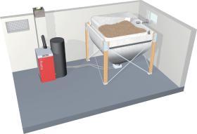
Figure 6-12 shows an example of a pellet-fired boiler that is automatically supplied from an inside pellet storage hopper. Systems that supply both space heating and domestic hot water can be designed around wood-fired and pellet-fired boilers. These systems usually include a well-insulated thermal storage tank that can absorb any excess heat production from the boiler when its output exceeds the current heating load.
For a more in-depth discussion on Solid Fuel Boilers:

