The use of multiple circulators allows design flexibility that is not possible in single circulator systems. This section discusses both “traditional” and novel approaches for systems with multiple circulators. The discussion begins with a design goal that is desirable in any system containing two or more independently controlled circulators. That goal is hydraulic separation.
Preface
When two or more circulators operate simultaneously in the same system, each attempts to establish differential pressures based on their own pump curves. Ideally, each circulator will establish a differential pressure and flow rate that is unaffected by the presence of another operating circulator in the system. When this desirable condition is achieved, the circulators are said to be hydraulically separated from each other.
Conversely, the lack of hydraulic separation can create very undesirable operating conditions in which circulators interfere with each other. The resulting flows and rates of heat transport within the system can be greatly affected by such interference, often to the detriment of proper heat delivery.
The degree to which two or more operating circulators interact with each other depends on the head loss within the piping path they have in common. This piping path is called the common piping, since it is shared by both circuits. The lower the head loss of the common piping, the less the circulators will interfere with each other.
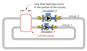
Consider the system shown in Figure 4-1. In this system, both circuits share common piping. The “spacious” geometry of this common piping creates very low flow velocity through it. As a result, very little head loss can occur across it.
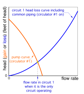
Assume that circulator 1 is operating, and circulator 2 is off. The blue circuit head loss curve shown in Figure 4-2 applies to this situation. The point where the blue circuit head loss curve crosses the orange pump curve for circulator 1 establishes the flow rate in circuit 1.
Next, assume circulator 2 is turned on, while circulator 1 remains on. The flow rate through the common piping increases, and so does the head loss across it. However, because of its spacious geometry, the increase in head loss across the common piping is very small. The system head loss curve that is now “seen” by circulator 1 will steepen, but very slightly. It is shown as the green curve in Figure 4-3.
The operating point of circuit 1 has moved very slightly to the left and slightly upward. This implies that the flow rate through circuit 1 has decreased very slightly. This very small change in flow rate is indicated in Figure 4-3. Such a small change in flow rate will have virtually no effect on the ability of circuit 1 to deliver heat. Thus, the interference created when circulator 2 turned on is of no consequence. This arrangement provides acceptable hydraulic separation between the two circulators.
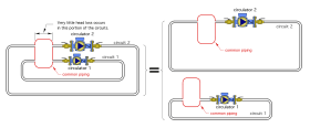
One can think of (and design) circuits that are known to have a high degree of hydraulic separation as if they were completely independent of each other, as illustrated in Figure 4-4.
The required hydraulic performance of each circuit can be determined as if it were a standalone circuit, unaffected by the other circuits in the system. This is a very powerful concept that simplifies design and troubleshooting.
To summarize: By keeping the head loss of the common piping shared by two or more circuits, each with their own circulator, as low as possible, the system achieves a high degree of hydraulic separation between the circulators. This point will be reinforced and repeated as several multiple circulator systems are discussed.
idronics™ #15 describes several methods for achieving hydraulic separation in multi-circulator systems.
Zoning with Circulators
One common method of zoning hydronic systems in North America is by using a separate circulator for each zone circuit. Figure 4-5 illustrates the concept.
Each of the 4 zone circuits contains a circulator, and each of those circulators contains an internal spring-loaded check valve assembly.
When the thermostat in a given zone calls for heat, its associated zone circulator is turned on, and the heat source is enabled to operate. Heated water is routed to the active zone and comes back to the return header after delivering heat to the heat emitters in that zone.
The dashed lines seen in Figure 4-5 identify the common piping in the system. The head loss of this common piping should be as low as possible to provide good hydraulic separation of the circulators. The headers should be short and generously sized.
A suggested guideline is to size headers for a flow velocity in the range of 2 to 4 feet per second when all the circulators supplied by the header are operating. Low flow velocity creates minimum head loss.
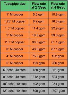
Figure 4-6 lists the flow rates corresponding to flow velocities of 2 feet per second and 4 feet per second for type M copper tubing in sizes from 1-inch to 4-inch, and in schedule 40 steel for larger pipe sizes.
The head loss of the boiler shown in Figure 4-5 is assumed to be low. This is typical for cast iron sectional boilers and boilers with steel fire tube heat exchangers.
The spring-loaded check valve within each zone circulator does two things:
1. It prevents thermosiphoning of hot water from the boiler into an inactive zone circuit.
2. It prevents flow reversal through inactive zones when other zones are operating.
The spring-loaded check valve used in most circulators has a forward opening pressure requirement of 0.3 and 0.5 psi. This is sufficient to prevent the relatively weak pressure differential created by buoyancy differences between the hot and cool water from establishing an undesirable thermosiphon flow within an inactive zone circuit.
For the internal spring-loaded check valve to be effective, the circulator must be mounted on the supply side of the zone circuit, as shown in Figure 4-5. If the circulators used do not have internal check valves, an external spring-loaded check valve with comparable forward open pressure can be used. It should be mounted at least 12 pipe diameters downstream of the zone circulator outlet to minimize any potential for rattling due to turbulent flow exiting the circulator.
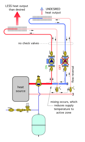
The spring-loaded check valve’s ability to prevent flow reversal through an inactive zone circuit is equally important. Figure 4-7 illustrates the potential flow reversal path in a system with two zone circuits, neither of which has a check valve, assuming that one zone circulator is operating while the other is not.
Notice that the flow returning to the lower header from the active zone “splits” at the tee below the purging valve. Some of it passes back into the heat source as desired. The rest passes backward through the other (supposedly inactive) zone circuit.
Keep in mind that return flow in some systems can be quite hot, perhaps even 160ºF. Water at elevated temperatures flowing backward through an inactive zone circuit will dissipate heat through the heat emitters in that circuit. Such heat output is unnecessary and undesired. Be sure that check valves are in place to prevent such heat migration.
Primary/Secondary Systems
In addition to zoning, many hydronic systems serve multiple heating loads, each of which can independently call for heat. An example of a multi-load system would be one that provides some space heating through fin-tube baseboard, additional space heating through low temperature radiant panels, provides domestic water heating, and also provides snow melting for the entry area of a building.
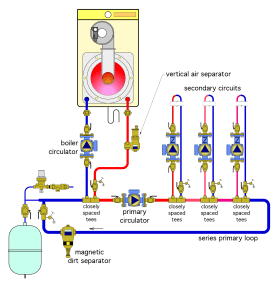
One approach to piping such a system is to use a circulator for each load and connect all the loads to a common piping loop. This is called a series primary/ secondary system. An example of such a system is shown in Figure 4-8.
In this system, each of the load circuits (also referred to as “secondary circuits”) connects to the primary loop using a pair of closely spaced tees. Because these tees are as close as possible, there is very little pressure drop between them. Thus, there is very little tendency for flow to be induced within any inactive secondary circuit, even though there is flow in the primary loop.
Each pair of closely spaced tees provides hydraulic separation between the primary loop and its associated secondary circuit.
When a given secondary circuit needs to deliver heat, its circulator is turned on. The secondary circuit draws heated water from the primary loop, sends it through the secondary circuit, and returns the cooler flow downstream of the heat emitters back to the primary loop.
The high flow resistance mod/con boiler shown in Figure 4-8 is also connected to the primary loop using a pair of closely spaced tees. Those tees provide hydraulic separation between the boiler’s circulator and the primary loop circulator.
Although hydraulic separation exists between all circulators, so does an undesirable effect; a drop in supply water temperature from one secondary circuit to the next whenever two or more secondary circuits are operating simultaneously. Although there are situations in which this temperature drop doesn’t present a problem, it does add complications that designers must compensate for after assessing.
The temperature drop across each set of closely spaced tees can be calculated using Formula 4-1 (repeated below).
$$\Delta T = {Q \over 500* f}$$
Where:
$\Delta T$ = temperature drop across the closely spaced tees of an active secondary circuit (ºF)
$Q$ = rate of heat output from the secondary circuit (Btu/hr)
$f$ = flow rate in the primary loop (gpm)
$500$ = a constant based on properties of water. Change the 500 to 485 if a 30% glycol solution is used in the circuit, or to 450 if a 50% glycol solution is used.
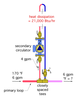
Example: Figure 4-9 shows a situation with water at 170ºF and 6 gpm flowing along a primary loop. A secondary circuit is operating at a flow rate of 4 gpm, and dissipating heat at a rate of 21,000 Btu/hr. The fluid in the system is water. Determine the temperature drop across the closely spaced tees.
Solution: Putting the stated operating conditions into Formula 3-1 and solving yields:
$$\Delta T = {Q \over 500* f} = {21,000 \over 500* 6}=7^o F$$
$$T_{out} = (T_{in}-\Delta T) = (170-7) = 163^o F$$
Discussion: Notice that the flow rate in the primary loop (and not in the secondary circuit) was used in this calculation. The temperature drop depends only on the primary loop flow rate and the rate of heat dissipation by the heat emitters in the secondary circuit. The water temperature passing to the next set of closely spaced tees in the primary loop will be approximately 163ºF, assuming that the primary loop piping is well insulated. This calculation can be repeated for each operating secondary circuit in the system to determine the total temperature drop around the primary loop. Assuming that the flow rate in the primary loop doesn’t change, the total temperature drop around the primary loop can vary considerably depending on which secondary circuits are operating at any time.
The sequential temperature drop across each secondary circuit connection is a consequence of the series arrangement of the closely space tees. It is not a desirable condition.
Parallel Primary Loops
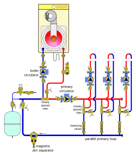
One way to overcome the sequential temperature drop effect associated with series primary loops is to create a parallel primary loop, as shown in Figure 4-10.
A parallel primary loop is divided into two or more “crossover bridges.” A pair of closely spaced tees within each crossover bridge provides hydraulic separation between each secondary circuit and the parallel primary loop.
Unlike a system with a series primary loop, a system with a parallel primary loop provides the same supply water temperature to each secondary circuit, regardless of which secondary circuits are operating. However, this benefit is achieved through more complicated and costly piping. Notice that each crossover bridge contains a flow-balancing valve. These valves are needed to set the flow through each crossover bridge in proportion to the thermal load served by the secondary circuit supplied from that bridge. If these valves are not present and properly adjusted, there may be problems such as inadequate flows through the crossover bridges located farther away from the primary circulator.
Another important consideration is that both series and parallel primary/secondary systems require a primary circulator. This circulator has to operate whenever any one or more of the secondary circuits is active.
The primary loop circulator adds to the installed cost of the system. More importantly, it adds to the system’s operating cost over its entire life. Even one small primary loop circulator can have operating costs that total $1,000 or more over a typical 20-year system design life. Larger primary loop circulators can have life cycle operating costs of several thousand dollars.
Example: Consider a primary loop circulator that must produce a flow rate of 50 gpm, with a corresponding head of 15 feet (which is evidenced by a pressure gain of 6.35 psi across the circulator). Assume the circulator is a typical wet-rotor design and has a wire-to-water efficiency of 25% at these operating conditions. The estimated input power to operate this circulator is:
$$W = {0.4344 \times f \times \Delta P\over 0.25} = {0.4344 \times 50 \times 6.35\over 0.25} = 552 watts$$
If this primary loop circulator were to operate for 3000 hours each year, and the local cost of electrical energy was $0.10/kwhr, the annual operating cost would be:
$$1st\,year\,cost = \bigg({3000\ hr \over yr} \bigg) \bigg({552\ w \over 1} \bigg) \bigg({1\ kwhr \over 1000\ whr} \bigg) \bigg({$0.10 \over kwhr}\bigg)= $165.60$$
Furthermore, if the cost of electricity were to inflate at 4% each year, the total operating cost of this circulator over a 20-year period would be:
$$C_T = C_1 \times \bigg({(1+i)^N - 1\over i} \bigg)= $165.60 \times \bigg({(1+0.04)^{20} - 1\over 0.04} \bigg)= $4,931$$
This cost is only for operation of the primary loop circulator. It does not include purchase, installation or maintenance of the circulator over time.
Beyond Primary/Secondary Systems
It is possible to retain the hydraulic separation benefits of primary/secondary piping, and deliver equal supply water temperature to each load circuit without having to construct a parallel primary loop, or use a dedicated primary loop circulator.
Use a Hydraulic Separator
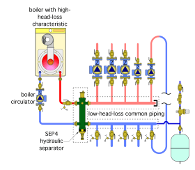
One way to provide hydraulic separation between multiple circulators and provide equal supply water temperature to each load is by installing a device called a hydraulic separator, as shown in Figure 4-11.
The shape of a hydraulic separator minimizes any dynamic pressure drop through it in either the vertical or horizontal direction. When combined with short and generously sized headers, the common piping in the system, identified by the dashed lines in Figure 4-11, has very low head loss. The result is excellent hydraulic separation between all circulators in the system.
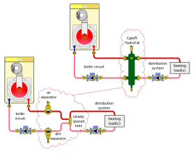
Some hydraulic separators contain coalescing media that allow them to provide high-performance air and dirt separation. As such, they can eliminate the need to install separate air and dirt separating devices in the system, as illustrated in Figure 4-12.
The use of a hydraulic separator eliminates the need to create a primary loop. With no primary loop, there is no need of a primary loop circulator. This can significantly reduce installation cost, as well as operating cost over the life of the system.
idronics™ #15 provides a more detailed discussion of hydraulic separators.


