Many modern hydronic distribution systems require two or more supply water temperatures. At certain times, these different supply water temperatures must be created simultaneously, but remain independently controlled.
The most common approach is to select a heat source capable of heating water to the highest required temperature for the system, and combine this with one or more mixing assemblies that can reduce that temperature as required in other portions of the system. An example would be a system that supplies 180ºF water to fin-tube baseboard on one level of a home, while simultaneously supplying 100ºF water to radiant floor-heating circuits in the basement slab.
These multi-temperature systems are easy to create using modern hydronic hardware and control methods. In the scenario just described, a boiler would be set to produce water at 180ºF. Some of that water would be routed directly to the fin-tube baseboard portion of the system without any mixing. In another portion of the system, a mixing assembly would be configured to supply 100ºF water to the radiant panel circuits. It would do so by blending a portion of the cooler water returning from the radiant panel circuits with some of the 180ºF water from the boiler.
idronics™ #7 provides a more detailed discussion of mixing theory.
Concept of a Mixing Assembly
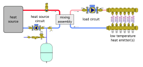
It is helpful to visualize a hydronic system that involves mixing as two circuits connected by a mixing assembly, as shown in Figure 5-1.
One circuit is called the “heat source circuit.” It includes one or more heat sources, as well as a circulator, and usually some “trim” such as an air separator, make-up water assembly and purging valve. The heat source circuit is responsible for creating the highest water temperature in the system and delivering it to the mixing assembly.
The other circuit is called the “load circuit.” It contains piping for one or more heating zones, one or more circulators, and the heat emitters. The load circuit is responsible for delivering water received from the mixing assembly to all heat emitters in the system.
These two circuits are connected by a “bridge” which is called the mixing assembly. There are several hardware devices and arrangements that could form the mixing assembly. They will be discussed later. For now, focus on the mixing assembly as the link between where heated water is created, and where that heat needs to be delivered. No heat can pass from the heat source circuit to the load circuit without passing across the mixing assembly. Thus, by controlling the mixing assembly, one can completely regulate heat transfer from heat source to load from zero up to the maximum heating capacity of the heat source. The ability of the mixing assembly to completely control the rate of heat transfer from source to load will reveal itself as critically important in many situations.
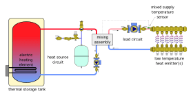
In some systems, the only function of the mixing assembly is to create the necessary supply water temperature to the load circuit. For example, imagine a system in which the heat source for a low temperature distribution system is a thermal storage tank that has been heated by an electric element, as shown in Figure 5-2.
In this system, the mixing assembly’s only responsibility is to monitor the temperature of the water supplied to the low temperature heat emitters and adjust the proportions of hot water from the thermal storage tank with cooler water returning from the heat emitters, so that the supply temperature remains at the desired value.
Preventing Sustained Flue Gas Condensation
Many hydronic systems use “conventional” boilers burning a hydrocarbon-based fuel such as natural gas, propane, fuel oil or wood. These boilers have been designed to operate at water temperatures that do not create sustained condensation of the flue gases within the boiler or its exhaust system. In these systems, the mixing assembly must provide a second function: Protecting the conventional boiler from operating with sustained flue gas condensation.
Maintaining the boiler’s inlet water temperature above a specified value prevents sustained flue gas condensation. That value varies with the design of the boiler and the type of fuel being burned. Boiler manufacturers should be consulted for specific minimum inlet water temperature requirements. In the absence of manufacturer recommended values, a minimum inlet water temperature of 130ºF is usually sufficient to prevent sustained flue gas condensation.
One of the most reliable methods of controlling boiler inlet water temperature is through use of a properly controlled mixing assembly. However, to be effective, that mixing assembly must measure and react to changes in boiler inlet temperature. Otherwise the mixing assembly is “blind” to what is happening at the boiler inlet, and cannot assure the boiler is protected against sustained flue gas condensation.
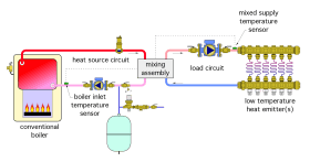
Figure 5-3 shows a modified version of Figure 5-1. The heat source is now a conventional boiler. A temperature sensor that measures boiler inlet water temperature has been added. That sensor provides feedback to the mixing assembly.
Whenever the mixing assembly in Figure 5-3 determines that the boiler inlet temperature is at or below a user-set minimum value, it reacts by reducing the rate of hot water flow from the boiler to the mixing assembly. This control action allows the full heat production of the boiler to pass to the distribution system, but does not allow the distribution system to extract heat from the water circulating through it at a rate greater than the rate of heat production. This action also “lifts” the combustion side of the boiler’s heat exchanger above the dewpoint of the exhaust gases.
idronics™ #7 provides a more detailed discussion of protecting conventional boilers against sustained flue gas condensation.
Mixing with 3-Way Thermostatic Valves
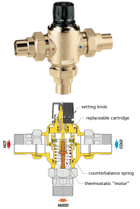
One device that is often used for mixing is a 3-way thermostatic valve. Figure 5-4 shows an example of such a valve.
All 3-way mixing valves have two inlet ports, one for hot water and the other for cooler water. The inlet flows merge within the valve to create a single outlet flow at the mixed temperature condition.
3-way thermostatic valves use a non-electric thermostatic element to modulate the two incoming flows in an attempt to create an outlet flow at the temperature set using the valve’s knob.
If the mixed fluid temperature flowing across the thermostatic element decreases below the setting, the valve’s hot port opens farther as its cold port moves toward (but not necessarily to) its closed position. If the mixed fluid temperature flowing across the thermostatic element rises, the hot port begins to close as the cool port opens. The valve constantly monitors and responds to the fluid temperature leaving its mixed port. High-quality thermostatic mixing valves can respond to temperature changes within a few seconds.
Always Check the Valve's Cv Value
When selecting a 3-way thermostatic valve for a hydronic mixing application, it is important to consider its flow resistance. The head loss across the valve at a given flow rate can be calculated by knowing the valve’s flow coefficient (also known as its Cv).
The relationship between head loss, flow rate and valve Cv is given by Formula 5-1:
$$H_{loss}= \bigg({2.308\over C_v^2} \bigg) f^2$$
Where:
$H_{loss}$= head loss across valve (ft)
$C_v$= flow coefficient of valve
$f$= flow rate through mixed port of valve (gpm)
For example, the head loss experienced across a 3-way thermostatic valve with a $C_v$ of 3.5, while passing 6 gpm through its mixed port would be:
$$H_{loss}= \bigg({2.308\over C_v^2} \bigg) f^2 = \bigg({2.308\over 3.5^2} \bigg) 6^2 = 6.8ft$$
This head loss is equivalent to about 98 feet of 3/4-inch type M copper tubing operating at the same 6 gpm flow rate, or 343 feet of 1-inch type M copper tubing operating at 6 gpm. This is a relatively high head loss that could significantly reduce flow through the distribution system.
A guideline in selecting 3-way thermostatic valves is to match the Cv of the valve with the full-load flow rate through the valve (e.g., with all downstream zones operating). Sizing the valve to this guideline will result in a nominal 1 psi pressure drop and a nominal 2.3-foot head loss across the valve. Do not assume that just because the valve has piping connections that match the piping where it will be installed, it has the proper flow resistance characteristics.
Piping for 3-Way Thermostatic Mixing Valves
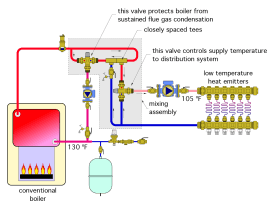
The piping configuration used for 3-way thermostatic mixing valves depends on the heat source used. If that heat source is a conventional boiler, and thus requires protection against sustained flue gas condensation, it is necessary to install two 3-way valves, as shown in Figure 5-5.
One of the valves in Figure 5-5 provides the mixing point to create the required supply water temperature for the low temperature distribution system. The other 3-way thermostatic valve creates the second mixing point needed to boost boiler inlet temperature high enough to avoid sustained flue gas condensation.
Assume the upper valve in Figure 5-5 is set for 130ºF, and the lower valve is set for 105ºF. When the boiler is first fired, the water temperature leaving the boiler is much lower than 130ºF. Under this condition, the hot port of the upper 3-way valve is fully open, while its cold port is fully closed. This routes all water coming from the boiler’s outlet back to the boiler’s inlet. None of this water is “released” to the remainder of the system.
The lower thermostatic valve also has its hot port fully open and its cold port fully closed when the system first turns on. All flow returning from the manifold station is routed to the left side of the closely spaced tees. Since no flow is entering the right-side tee, the cool water entering the right tee makes a “U-turn” and heads back to the hot port of the lower mixing valve. From there it passes out to the distribution system, albeit without picking up any heat for the time being.
Because no heat is being released to the load, the boiler is now warming up as fast as possible. When the temperature of the water leaving the upper mixing valve reaches 130ºF, it begins opening its cold port and closing its hot port in an attempt to keep the mixed water temperature close to 130ºF. Heated water can now pass around the upper right side of the schematic, enter the right side of the closely spaced tees, and pass down to the hot port of the lower 3-way valve. The lower valve will adjust as necessary to maintain a 105ºF supply temperature to the manifold station.
The combination of two valves prioritizes protection against sustained flue gas condensation and provides stable supply water temperature to the distribution system.
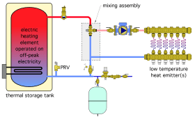
When the heat source in the system does not require protection against sustained flue gas condensation, and is not sensitive to low flow rates, a single 3-way thermostatic valve can be used to provide regulation of supply water temperature. An example of such an application is shown in Figure 5-6.
In this system, the function of the 3-way thermostatic mixing valve is to protect the low temperature heat emitters against potentially high temperature water in the thermal storage tank.
Assume that the heat emitters require a supply water temperature of 105 ºF. Whenever water from the thermal storage tank exceeds this temperature, the 3-way thermostatic valve mixes in a portion of the cooler water returning from the low temperature heat emitters to maintain supply temperature close to 105ºF.
Distribution Stations Using 3-Way Thermostatic Valves
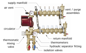
The combination of a 3-way thermostatic mixing valve, circulator and manifold station is an often-used piping assembly. Caleffi has combined these components, along with a means of hydraulic separation, into a pre-engineered mixing station, as seen in Figure 5-7.
This distribution station reduces installation time and space requirements. Its integral thermostatic mixing valve reduces incoming water temperature to that required by the manifold circuits. The distribution station also provides hardware for venting and purging, and indication of both supply and return temperatures.
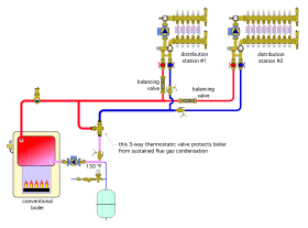
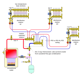
Figure 5-8 shows how two of these distribution stations could be supplied from a single conventional boiler.
Each distribution station can be set up with different numbers of circuits, and each can operate at a different supply temperature. The boiler must supply water at or above the highest of these supply temperatures. A separate 3-way thermostatic valve is installed to protect the boiler from sustained flue gas condensation.
The bypass built into each distribution station provides hydraulic separation between the circulator in the distribution station, and the boiler circulator. The boiler circulator is responsible to move water to each distribution station, but not through the radiant panel circuits connected to that distribution station.
When the water temperature leaving the boiler is relatively high in comparison to the water temperature on the return side of the distribution stations, the flow rate supplied to each distribution station can be quite low. For example, if the boiler supplied 180ºF water under design load conditions, and the return water temperature from a distribution station supplying a 20,000 Btu/hr load is 95ºF, the flow rate that needs to be delivered to the distribution station is:
Formula 5-2:
$$f= \bigg( {Q\over 490*\Delta T} \bigg) = \bigg( {20,000\over 490*(180-95)} \bigg) = 0.48 gpm$$
This relatively small flow rate could easily be conveyed through 1/2-inch PEX-AL-PEX tubing. This approach can simplify the installation and reduce cost relative to systems that use rigid tubing between the mechanical room and each distribution station. Figure 5-9 shows an example of this concept. A “master manifold” is used to divide flow from the boiler into each of three distribution circuits made of flexible PEX or PEX-AL-PEX tubing.
Mixing with 3-Way Motorized Valves
3-way mixing valves can also be combined with motorized actuators that are operated by electronic controllers.
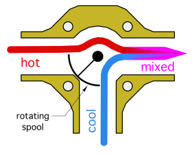
The type of 3-way valve body commonly used for motorized operation is different from that used for thermostatic operation. Rotary valve bodies are commonly used for motorized 3-way valves, in contrast to the linear shaft movement used in most thermostatic 3-way mixing valves. The cross section of a typical 3-way rotary mixing valve is shown in Figure 5-10.
The rotating spool within the valve is a segmented cylinder. Its angular position within the body determines how much hot versus cool water enters the valve. Clockwise rotation increases cool water entry while simultaneously decreasing hot water entry, and vice versa. The two flow streams come together within the valve. Turbulence within the valve creates good mixing.
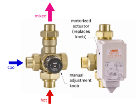
An example of a Caleffi 3-way mixing valve with motorized actuator is shown in Figure 5-11.
The mixing valve body is supplied with a knob, which allows it to be operated manually. For motorized applications, this knob is removed and replaced with a motorized actuator, which fastens to the valve body, as seen on the right side of Figure 5-11. The actuator’s shaft is coupled to the valve’s shaft. The gear motor assembly inside the actuator provides very slow rotation of the valve’s shaft. Slow rotation prevents rapid temperature changes and improves control stability. A typical motorized actuator can require two to three minutes to rotate the valve’s shaft by 90 degrees.
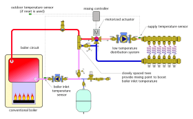
Figure 5-12 shows typical piping for a 3-way motorized mixing valve that is supplying a low temperature distribution system using heat supplied by a conventional boiler.
The actuator motor driving a 3-way motorized mixing valve must be electronically controlled. When energized, the mixing controller continuously queries one or more temperature sensors, and uses this information along with its settings to operate the motorized actuator. This rotates the valve shaft one way or another, or if no signal is sent to the actuator, leaves the shaft in its current position.
Most modern mixing controllers that are designed to operate motorized valves are equipped with a sensor to measure boiler inlet temperature. The controller can then respond to this temperature by automatically reducing hot water flow into the mixing valve when boiler inlet temperature is at or below a user-selected minimum temperature that prevents sustained flue gas condensation. This feature allows a single 3-way motorized mixing valve to protect the boiler and regulate supply water temperature. Most mixing valve controllers also have the option of providing either a fixed setpoint or full outdoor reset of the water temperature supplied to the distribution system.
The boiler loop and boiler circulator shown in Figure 5-12 are essential for creating a second mixing point (within the lower of the two closely spaced tees). The mixing point boosts boiler inlet temperature as necessary to prevent sustained flue gas condensation within the boiler.


