PREFACE
The fundamental objectives of adding a recirculating function to a domestic hot water delivery system are:
1. To ensure delivery of heated domestic water at all fixtures within 1-3 seconds of opening a faucet, or otherwise creating a demand.
2. To significantly reduce water waste associated with clearing hot water piping of cooler water after a period of no demand.
The basic recirculation system shown in Figure 1-3 could achieve these objectives. However, the plumbing designer also needs to ensure that:
3. The water temperature delivered from any fixture is safe under all conditions.
4. The domestic hot water delivery system does not create conditions favorable to growth of pathogens such as Legionella bacteria.
This section combines all four requirements into systems that are suitable for homes or small commercial buildings where a single-loop recirculating system is feasible. Later sections expand these concepts into more elaborate systems suitable for larger commercial or institutional buildings.
BURN PROTECTION
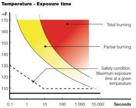
One of the greatest hazards associated with heated water is the risk of moderate to severe burns when skin is exposed to excessively heated water at sinks, showers, bathtubs or other fixtures. The ability of hot water to burn human skin depends on its temperature and exposure time. The higher the water temperature, the shorter the time required to produce a burn of a given severity. Figure 2-1 shows how burn severity of adult skin is affected by water temperature and exposure time.
In a shower, adult skin can be exposed to water at 110ºF indefinitely without risk of burns. However, at temperatures above 110ºF the risk of burns increases rapidly. Water at 120ºF will create a first-degree burn to adult skin in approximately 8 minutes. Water at 130ºF will cause first-degree burns to adult skin in about 10 seconds. Water at 160ºF will cause a first-degree burn to adult skin in less than 1 second! Children can experience similar burns in half or less of the time required to burn an adult. Elderly people are also more susceptible to burns due to reduced nerve sensitively and slower reaction times.
The consequences of serious and possibly irreversible burns caused by overheated domestic water should never be taken lightly. Beyond the potentially life-altering medical issues faced by the victim is the legal liability associated with designing, installing or adjusting the domestic water heating system that caused the burn. It is therefore a highly recommended and often legally mandated practice to equip domestic hot water systems with devices that reliably protect against such conditions.
Unless otherwise required by local code or regulation, domestic hot water should never be delivered from fixtures intended to supply water directly to human skin at temperatures above 120ºF. In most cases, water at a temperature of 110ºF is acceptable for showers, bathtubs and lavatories. Most devices designed to heat domestic water are supplied with thermostatic controls that should limit water temperature. The accuracy of these control devices varies considerably. Variations between the temperature setting of the control device and the measured water temperature leaving the water heater can easily be 10ºF or more. This variation could make the difference between an acceptable and safe water temperature at the point-of-use, versus a water temperature that could lead to a serious burn.
Beyond the accuracy and repeatability of the temperature control device on the water heater is the relative ease of adjusting this device. A person who is frustrated with hot water delivery temperatures that are too cool for their comfort may overcorrect by turning the temperature control device up well beyond point of safe delivery temperature.It’s also possible that a hot water system that has to deliver hot water at temperatures as high as 195ºF for sanitation purposes also supplies hot water to a lavatory for handwashing. Without proper anti-scald mixing provisions, it’s inevitable that such a situation will eventually cause serious burns.
Another possibility is that the hot water system that normally supplies water at perhaps 120ºF, has been specifically designed to boost the water temperature in the system to 160ºF or higher at certain times to kill pathogens such as Legionella bacteria. During this type of “thermal disinfection” cycle, it’s imperative to protect all hot water fixtures in the system from dangerously high delivery temperature. All these possibilities demonstrate that it’s not a good idea, or even legal, to rely on the temperature control device at the water heater to consistently deliver safe hot water temperatures at the points where hot water is drawn from the system (e.g., the “points of use”).
POINT-OF-USE TEMPERATURE PROTECTION
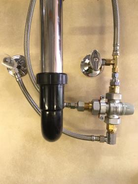
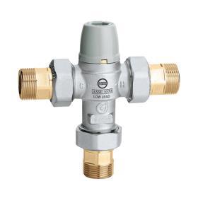
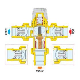
Figure 2-3 shows an ASSE 1070-listed thermostatic mixing valve that is equipped with MPT connections. Thermostatic mixing valves listed to the ASSE 1070 standard are designed to be installed close to the fixture from which hot water will be drawn. As such, they are called “point-of-use” mixing valves. Caleffi ASSE 1070 mixing valves can be configured with tail pieces to match PEX, MPT threads or soldered connections.
These valves continuously adjust the proportions of entering hot and cold water so that the mixed water stream leaving the valve remains at a set (and safe) temperature. This regulation is created by the movement of a non-electric thermostatic element within the valve, as shown in Figure 2-4. The thermostatic element contains a special wax that expands and contracts with temperature changes. This element is fully immersed in the mixed-flow stream leaving the valve, and thus it continually reacts to changing inlet temperatures and flow rates. The thermostatic element adjusts the open area of the ports that allow hot water and cold water to enter the valve. As the open area of the hot water inlet port decreases, the open area of the cold water inlet passage increases, and vice versa. If the temperature or pressure at either inlet port changes, the valve quickly and automatically compensates to maintain the set outlet temperature.
Thermostatic mixing valves listed under the ASSE 1070 standard are also pressure compensated. If cold water flow to the valve is interrupted, the valve must immediately reduce the flow of hot water leaving the valve to a small percentage of normal flow. This action requires a minimum temperature difference of 18ºF (10ºC) between the hot water inlet and mixed water outlet. Valves listed to the ASSE 1070 standard must also have internal check valves in both inlet ports.
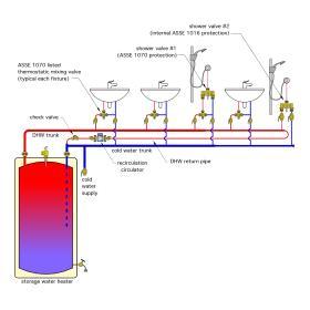
Figure 2-5 shows how the basic recirculation system of Figure 1-3 can be modified to include an ASSE 1070-listed thermostatic mixing valve at each fixture. Shower valve #2 in Figure 2-5 is assumed to contain an internal thermostatic and pressure-compensated assembly that provides protection based on the ASSE 1016 standard, and thus no external mixing valve is needed. Many shower valves now have this capability. However, older shower valves may not have any temperature or pressure compensation. Shower valve #1 in Figure 2-5 is assumed to be such a valve. As such, an external ASSE 1070 thermostatic mixing valve has been installed.
The benefits of having an ASSE 1070 thermostatic mixing valve at each fixture include:
1. The maximum supply water temperature can be independently adjusted at each fixture. This is especially useful in systems that supply hot water for washing or sterilization at temperatures well above 120ºF, but also supply hot water to lavatories, sinks or showers where skin contact occurs.
2. The water heater, hot water trunk and recirculation return piping can operate continuously, or based on other specific conditions, at temperatures high enough to kill pathogens such as Legionella bacteria.
POINT-OF-DISTRIBUTION TEMPERATURE PROTECTION
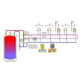
When all fixtures served by the system require the same maximum hot water temperature, and the heat source will be operated at higher temperature to eliminate pathogens, a single “point-ofdistribution” thermostatic mixing valve with an ASSE 1017 listing can be used, as shown in Figure 2-6. In any recirculating hot water distribution system, there will be times when the circulator is operating but no hot water is being drawn at the fixtures. Under this condition, heat continually dissipates from the piping forming the recirculation loop. If the loop is relatively short and well insulated, the rate of heat loss should be very small. If the loop is long and uninsulated, the rate of heat loss could be substantially higher.
To maintain the recirculating hot water at the desired delivery temperature, the heat lost from the loop must be replaced. This requires some water flow between the loop and the hot water source. In systems with point-of-distribution mixing valves that do not fully close their ports, the rate of heat transfer between the heat source and recirculation loop can be stabilized by installing and adjusting two valves. In Figure 2-6, these valves are identified as the “bridge valve” and “return valve”.
When there is no demand for hot water at the fixtures, the flow of return water in the recirculating loop will equal the rate of hot water flow from the tank to the inlet port of the mixing valve. This flow rate should be adjusted so that the rate of heat transfer from the tank to the recirculating loop exactly balances the rate of heat loss from the recirculating loop. This allows the water temperature leaving the temperature-activated mixing valve to remain stable. The bridge valve, and possibly the return valve, must be adjusted when there is no domestic water draw on the recirculating loop (e.g., all fixtures are off).
Begin with the bridge valve fully closed and the return valve fully open. Turn on the recirculating circulator and let it run for several minutes. Under this condition, the supply water temperature leaving the point-of-distribution mixing valve will likely be lower than the setting of the valve (since there is no flow returning to the water heater). Slowly open the bridge valve and monitor the temperature leaving the point-of-distribution mixing valve. It will begin rising as some water returns to the water heater and an equal flow of hot water moves from the water heater to the hot port of the mixing valve. When the temperature leaving the mixing valve remains stable and is at or very close to the temperature set on the point-of-distribution mixing valve, the bridge valve is correctly set.
The return valve can remain fully open unless a situation occurs where the bridge valve is fully open, but the temperature leaving the mixing valve is still too low. If this occurs, partially close the return valve to add flow resistance. This forces more flow through the bridge valve. Repeat the previously described procedure of slowly opening the bridge valve until the water temperature leaving the mixing valve is stable. In Figure 2-6 the hot water supply and return (recirculation) piping are shown with insulation. This significantly reduces heat loss, which decreases the required recirculation flow rate. Designers should check with local plumbing codes to verify any minimum insulation requirements for domestic hot water piping.
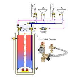
In systems where the point-of-distribution valve can fully close its ports, the bridge valve and return valve can be eliminated. Figure 2-7 shows an example of such a system using Caleffi’s TankMixer assembly, which meets ASSE 1017 protection standards and can fully close its hot port when necessary, thus eliminating the need for a bridge valve or a return valve.
The Caleffi TankMixer assembly provides all hardware necessary for point-of-distribution temperature protection, as well as recirculation. It is available with threaded, sweat and press fit connections. The latter, as shown in Figure 2-7, allows the complete assembly to be installed without any soldered joints. Designers should also note that use of a single thermostatically actuated point-of-distribution ASSE 1017 mixing valve that is set no higher than 120ºF does not protect the hot water distribution system from Legionella. Such protection requires higher water temperatures, which are discussed next.
LEGIONELLA PROTECTION
One biological impurity that can be present in domestic hot water systems is Legionella bacteria. There are currently over 40 known types of these bacteria, which are naturally present in rivers, lakes, wells or stagnant pools of water. These bacteria are also found in municipal water mains and can, to some extent, survive municipal water treatment processes.
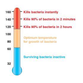
Legionella bacteria can multiply in water at temperatures between 68 and 122ºF. Below 68ºF, the bacteria are present, but remain dormant. Tempered water between 77 and 113ºF provides an optimum growth environment for Legionella bacteria. Growth is also aided by the presence of biofilms, mineral scale, sediment or other microorganisms within plumbing systems. Dead-leg plumbing systems that harbor stagnant water also provide an enhanced growth environment and should be avoided.
Figure 2-8 shows the relationship between the status of Legionella bacteria and the temperature of the water in which they exist. Legionella bacteria can be rapidly killed by maintaining heated domestic water at 140ºF or higher. Domestic hot water systems that maintain the heat source and distribution piping, including the return piping in a recirculating system at temperatures of 130ºF or higher, provide excellent protection against Legionella bacteria.
Domestic hot water systems that maintain the heat source and distribution piping, including the return piping in a recirculating system at temperatures of 130ºF or higher, provide excellent protection against Legionella bacteria. Some systems maintain these high water temperatures continuously. Other systems operate with a timed sterilization cycle in which the water temperature is elevated to 160ºF or higher and circulated through the entire recirculation system for a specific time. This sterilization cycle is typically activated at a time of reduced water usage, such as during nighttime hours in a residential system.
In the absence of specific codes or standards that require otherwise, the following water temperatures and associated cycle durations have been commonly used for once-per-day sterilization of domestic hot water delivery systems:
158ºF (70ºC) for 10 minutes
149ºF (65ºC) for 15 minutes
140ºF (60ºC) for 30 minutes
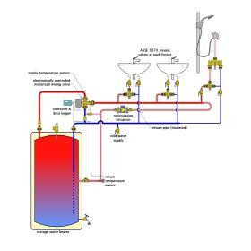
These temperatures and durations would be required at the hot water fixture farthest away from the hot water source. During the sterilization cycle, it is essential to protect fixtures against scalding hot water. Use of ASSE 1070 point-of-use mixing valves, as shown in Figure 2-5, can provide this protection. If a sterilization cycle is required, it is not possible to use a thermostatic point-of-distribution mixing valve, as shown in Figure 2-6. However, electronically-controlled mixing valves, in combination with proper controls, can allow for sterilization cycles in a recirculating system and provide reduced hot water temperatures at other times. Reducing the water temperature circulating through the system during non-sterilization periods reduces piping heat loss, and thus reduces fuel use.
Figure 2-9 shows the concept of a recirculating domestic hot water system using an electronically-controlled point-of-distribution mixing valve in combination with ASSE 1070-rated point-of-use thermostatic mixing valves at each fixture. The latter protect the fixtures from the high-temperature water circulated through the system during the sterilization cycle.
DESIGNING A SINGLE-LOOP RECIRCULATION SYSTEM
When hot water leaves a heat source and travels along piping, its temperature is continually decreasing due to heat loss from that piping. The farther the water travels along the piping, the lower its temperature becomes. In some systems, the temperature drop is quite small, perhaps only 1 or 2ºF due to short piping lengths and insulation around the piping. In systems with long runs of uninsulated piping carrying relatively high temperature water, the temperature drop can be substantial. This can lead to water temperatures at the farthest fixture that are either too low from a comfort standpoint or too low based on protection against Legionella growth. Thus, the piping path between the heat source and the farthest fixture requiring hot water becomes the focus.
The objective of a single-loop recirculation system is to establish a flow rate than can maintain a specific minimum supply water temperature at the fixture farthest from the heat source.
Meeting this objective requires a means to evaluate piping heat loss. That loss depends on the type of piping material(s) used, the pipe size and length, the water temperature inside the piping, the presence or absence of pipe insulation, and the air temperature surrounding the piping.
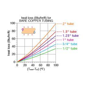
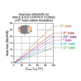
Figure 2-10a can be used to estimate the rate of heat loss from bare copper water tubing based on the difference in temperature between the water in the tube and the surrounding air temperature. Figure 2-10b can be used to estimate the heat loss from copper tubing wrapped with 1/2” thick elastomeric foam insulation, having an R-value of approximately 2 ºF•hr•ft2 /Btu.
To use the graphs in Figures 2-10a and 2-10b, subtract the air temperature surrounding the tube from the average water temperature inside the tube. Find this temperature difference on the horizontal axis. Draw a line up from the temperature difference to the sloping line corresponding to the tube size. Then draw a horizontal line from this point to the vertical axis, and read the heat loss per foot of tube from the vertical axis.
For example: Assume that a 1” bare copper tube carries water at an average temperature of 120ºF for a distance of 50 feet through a space where the air temperature is 55ºF. Estimate the total rate of heat loss from this tube.
Solution: Since this involves bare copper tubing, use Figure 2-10a. The difference between the average water temperature and surrounding air temperature is (120 - 55) = 65ºF. Draw a line from 65ºF on the horizontal axis up to the curve for 1” tubing, and then a horizontal line over to the vertical axis. The rate of heat loss is about 33 Btu/ hr per foot of tubing. The total heat loss from the 50-foot pipe is therefore about 33 x 50 = 1,650 Btu/hr.
By comparison, Figure 2-10b shows that heat loss from 1” copper piping wrapped with 1/2” thick elastomeric foam insulation is about 11.2 Btu/hr per foot, approximately one-third that of the uninsulated copper tube.
All heat lost from hot water distribution piping is undesirable from several standpoints:
• When the water in the pipe has cooled for several hours, it will be close to the surrounding air temperature. This cool water will likely be sent down the drain by a person who wants hot water for washing or other purposes. Significant quantities of water, as well as the energy to heat it, are lost each time this occurs.
• Waiting for hot water to flow from the fixture is annoying, especially in buildings with long “dead end” piping systems, where wait times can exceed 2 minutes. These wait times are often longest in the early morning following a period when little if any hot water has passed through the dead-end piping.
• Heat escaping from hot water piping adds to the building cooling load. The greater the cooling load, the greater the cost of operating the cooling system.
• Warm water standing in piping improves the growth environment for any Legionella bacteria.
RECIRCULATION FLOW RATE
The goal of a recirculating hot water distribution system is to keep the water temperature at the farthest fixture at a specified minimum value.
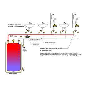
The temperature drop along the supply pipe can be estimated based on the size and length of piping in the loop, as well as the average water temperature, surrounding air temperature and the effect of any insulation on the pipe. The ASPE Domestic Water Heating Design manual, 2nd Edition, suggests a temperature drop of 5 to 10ºF between the hot water source to the farthest fixture served. Piping representing this path is shown in red in Figure 2-11.
Larger allowed temperature drops are possible and will decrease the recirculation flow rate, but they may result in water that is below an acceptable supply temperature at the farthest fixture. Assuming that each fixture in the system is protected by an ASSE 1070 thermostatic mixing valve, or that the fixture has internal ASSE 1016 protection, a suggested minimum hot water temperature at the farthest fixture is 130ºF.
Formula 2-1 can be used to estimate the necessary recirculation flow rate based on the heat loss of the supply piping and the allowed temperature drop.
Formula 2-1:
$$ f_r = {Q \over 500 \times \Delta T} $$
Where:
$f_r$ = the required recirculation flow rate (gpm)
$Q$ = total heat loss of the DHW supply piping (Btu/hr)
$\Delta T$ = the allowed temperature drop (ºF).
For example: Assume the domestic hot water piping from a heat source to the farthest fixture is 100 feet of 1” bare copper tubing. Water enters the piping at 135ºF, and the allowed temperature drop to the farthest fixture is 5ºF. The air temperature surrounding the piping is 70ºF. Determine the required recirculation flow rate.
Solution: Figure 2-10a can be used to estimate the heat loss of this piping. Since the supply temperature is 135ºF, and the allowable temperature drop is 5ºF, the average water temperature in the supply piping is 135 - 5/2 = 132.5ºF. The difference between this average water temperature and the air temperature surrounding the piping is 132.5 - 70 = 62.5ºF. Using Figure 2-10a, the estimated heat loss of the 1” bare copper piping is 32 Btu/hr/ft. Thus, the total estimated heat loss of the supply piping is:
$$ Q = \bigg(32{Btu \over hr \cdot ft}\bigg)(100ft)=3200{Btu \over hr} $$
The recirculation flow rate can now be determined using Formula 2-1:
$$ f = \bigg({Q \over 500 \times \Delta T}\bigg)=\bigg({3200 \over 500 \times 5}\bigg) = 1.28gpm$$
This low flow rate is easily handled by a 1/2” tube for the recirculation piping.
HEAD LOSS OF THE RECIRCULATION CIRCUIT
Once the recirculation flow rate is determined, the head loss of the complete recirculation loop (e.g., supply piping and return piping) needs to be estimated. The methods and data in Appendix B can be used to estimate this head loss.
For example, assume the supply piping to the farthest fixture is 100 feet of 1” bare copper tubing, and the return piping is 100 feet of 1/2” bare copper tubing. Using the formulas in Appendix B, the estimated head loss from 100 feet of 1” copper carrying water at 1.28 gpm, and at an average temperature of 132.5ºF is 0.131 feet.
$$ H_L = (acl)f^{1.75} = (0.048 \times 0.01776 \times 100)(1.28)^{1.75} = 0.131ft$$
The estimated head loss from 100 feet of 1/2” copper at 1.28 gpm, and at an average temperature of 132.5ºF is 2.47 feet.
$$ H_L = (acl)f^{1.75} = (0.048 \times 0.33352 \times 100)(1.28)^{1.75} = 0.247ft$$
The total estimated head loss of the straight piping in the circuit is thus (0.131 + 2.47) = 2.6 feet
This head loss will be increased by 10% to include an allowance for head loss of fittings. 2.6 x 1.1 = 2.86 feet
Thus, the total recirculation pumping requirement is 1.28 gpm at 2.86 feet.
This is a very small pumping requirement that can be handled by a small circulator designed specifically for recirculation systems. Such circulators typically operate with electrical inputs of 10 to 40 watts, and thus consume very little electrical energy.
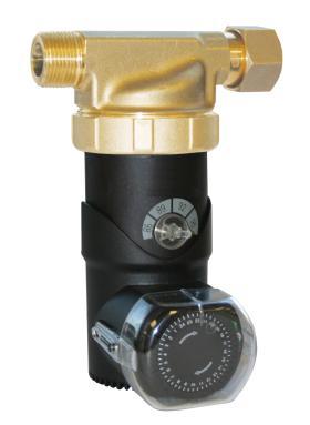
An example of a circulator specifically designed for domestic water recirculation is shown in Figure 2-12. This speed of this circulator can be manually adjusted to the flow and head requirements of the recirculation loop. This circulator also includes a manually adjusted timer that can be used to select when it should operate during a 24-hour day. Some DHW recirculation circulators are equipped with electronics that learn household hot water usage patterns over time. This information is used to turn the circulator on and off to match hot water usage patterns. The goal is to minimize thermal and electrical energy usage while also delivering reliable and nearly instant hot water at fixtures when it’s needed.

