PREFACE
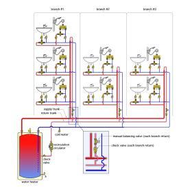
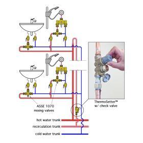
Many DHW delivery systems in larger buildings have multiple branches. A common piping layout uses hot and cold water “trunk” piping that serves multiple “branches.” Each branch serves multiple groups of fixtures. Figure 3-1 shows an example of such a system. The number of fixtures or fixture groups connected to each branch can be different, as can the distance from the hot water source to where each branch connects to the supply trunk.
Each branch has a recirculation return pipe that tees into a return “trunk.” Flow through the recirculation system is provided by a single circulator. Each branch recirculation pipe is equipped with a check valve. This valve is necessary to prevent flow reversal in the recirculation piping, which could otherwise be caused by sporadic pressure differential in the system due to DHW draws at certain fixtures.
When there is no demand for domestic hot water at the fixtures, this system is very similar to a hydronic heating or cooling distribution system with multiple branches and a single circulator. The initial (unbalanced) recirculation flow rates through each branch will depend on the pipe sizes, pipe lengths, fittings and distances from the circulator to the points where each branch connects to the hot water supply trunk and the recirculation return trunk.
Branches that are relatively close to the circulator and/or have shorter lengths of piping will have higher recirculation flow rates compared to branches that are farther from the circulator and/or have longer piping lengths. These initial branch recirculation flow rates may be much higher or lower than ideal. Branches with low recirculation rates could fail to provide adequate hot water supply temperature at the farthest fixtures. Branches with excessively high recirculation rates waste the head energy provided by the recirculation circulator. As is true with hydronic heating and cooling systems, multibranch domestic hot water recirculation systems require balancing to achieve optimal performance.
The system in Figure 3-1 shows a manually-adjusted balancing valve just upstream of where each recirculation return pipe enters the recirculation trunk pipe. These valves could also be installed at other locations on the recirculation return piping, provided those locations are easily accessible.
Manually-adjusted or dynamic balancing valves could be one of several options including:
a. fixed orifice manually-adjustable balancing valves with pressure ports
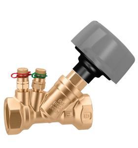
b. variable orifice manually-adjustable balancing valves with pressure ports
c. dynamic valves configured to maintain a specific and fixed flow rate
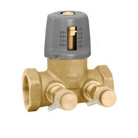
d. manually-adjustable balancing valves with integral flow meters
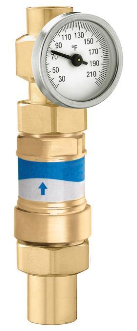
Examples of these valve options are shown in Figure 3-2.
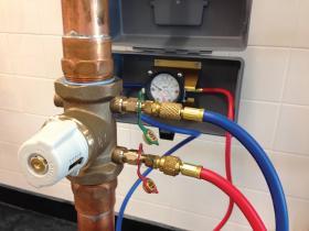
Caleffi fixed-orifice balancing valves (Figure 3-2a) and variable-orifice balancing valves (Figure 3-2b) allow precise adjustment of pressure drop across the valve. However, they do not directly indicate the flow rate passing through them. Instead, they rely on the use of a manometer for inferring flow rate based on a measured pressure drop. Figure 3-3 shows an example of a digital manometer connected to a balancing valve.
Some modern “digital” manometers can mathematically convert from the measured pressure drop across a specific valve to the inferred flow rate through that valve. Older manometers just indicate a differential pressure reading. The person setting the valve must then refer to a chart or slide rule to convert the measured pressure drop into an inferred flow rate.
Manually-adjustable balancing valves with fixed or variable orifices and pressure ports provide a relatively low-cost option for balancing. However, they also require the person doing the balancing to attach the manometer to each valve every time a flow reading is needed.
Furthermore, adjusting the flow rate through one manually-adjustable valve in a multi-branch system changes the flow rates through the other branches. Because of this, it’s often necessary to iteratively adjust each valve several times to achieve the target flow rate through each branch of the system.
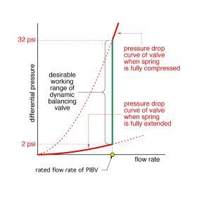
Dynamic pre-set valves, such as the Caleffi FlowCal valve shown in Figure 3-2c, are provided with a calibrated flow rate setting, such as 0.5 gpm. A spring-loaded mechanism within the valve modulates as the differential pressure across the valve varies within a control range such as 2-14 psi or 2-32 psi. This allows the valve to maintain its pre-set flow rate as long as the differential pressure across the valve stays within its control range, as shown in Figure 3-4.
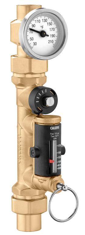
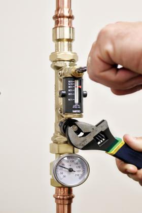
Balancing valves with integral flow meters, such as the Caleffi QuickSetter shown in Figure 3-2d, eliminate the need for a manometer. The flow rate through the valve can be read directly on the valve by pulling the spring loaded pin, as seen in Figure 3-5. This allows a magnet within the valve to position the flow indicator along the flow rate scale. The valve can then be set to the desired flow rate, and the pin released. The QuickSetter can accurately measure flow rate regardless of the orientation in which it’s installed.
No water passes directly by the QuickSetter’s flow indicator, eliminating concerns about scaling or dirt deposits on the indictor as the valve ages. QuickSetter valves are available in lead-free brass and with an optional thermometer, as seen in Figure 3-5.
In a multi-branch hydronic system, balancing procedures assume that stable flow is needed through all branches when that system operates under design load conditions. This is necessary to provide adequate heat output from all heat emitters. During partial load conditions, and in systems equipped with pressure-independent balancing valves, stable flow is to be maintained in all operating branches regardless of which other branches are off.
In a domestic hot water recirculating system, the objectives of balancing are:
- Provide a minimum hot water temperature to the farthest fixtures in all branches of the system.
- Prevent stagnant water within any part of the system that has little or no demand for hot water.
In a multi-branch DHW delivery system, there will be times of adequate DHW flow to the farthest fixture in each branch due to usage. Under such conditions, there is no need for recirculation flow.
At other times, there could be hours, even days, when there is no DHW demand from the farthest fixture, and thus recirculation flow is necessary to avoid a lengthy delay of DHW delivery when a demand does occur, as well as to avoid potential growth of pathogens due to stagnant water in that portion of the system.
The variability of these operating conditions, as well as the need to protect against biological growth, requires a different criterion for optimal balancing of a DHW recirculation system. That criterion is based on maintaining a minimum DHW temperature at the farthest fixture on each branch of the system, rather than maintaining a specific flow rate through each branch. If that minimum temperature results from a draw of DHW from the farthest fixture, there is no need for recirculation flow in that portion of the system. However, for optimal results, the system must automatically detect when a draw of DHW has not occurred within any branch of the system and initiate recirculation to ensure adequate temperature at the farthest fixture.
Maintaining recirculation in any portion of a DHW recirculation system that doesn’t need it wastes a portion of the head energy imparted to the water by the recirculation circulator, and thus wastes some of the electrical energy supplied to that circulator. Although one might argue that such energy waste is relatively small in a residential system, it can be very significant in large DHW recirculation systems serving hundreds, and in some buildings thousands, of fixtures.
Thus, optimal balancing of a recirculating DHW delivery system requires devices that can sense and react to the water temperature at the farthest fixture in each branch of the system. When a predetermined and sufficient hot water temperature is present at the farthest fixture, the only recirculation flow necessary is that required to continually monitor the hot water temperature at the farthest fixture If the predetermined and sufficient water temperature is not present at the farthest fixture, the balancing device must react by allowing increased recirculation flow to restore that temperature.
THERMAL BALANCING
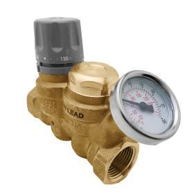
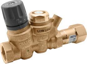
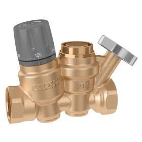
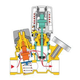
Caleffi has developed a unique product to address the specific balancing needs of a recirculating DHW distribution system. It’s called a ThermoSetter™ valve. One configuration of that valve is shown in Figure 3-6.
ThermoSetter™ valves are designed to be installed on the return piping of each recirculation branch as shown in Figure 3-7.
The basic configuration of the ThermoSetter™ valve provides a non-electric thermostatic balancing element similar to that used in ASSE 1017 mixing valves. This balancing element expands and contracts in response to the temperature of the water entering the valve. It allows full flow through the valve until the entering water temperature reaches a user set value between 95 and 140ºF, which implies there is hot water at that temperature throughout the hot water supply piping of that branch. When this temperature setting is reached, the balancing element reduces recirculation flow to a minimum value sufficient to monitor the entering water temperature and to ensure that the recirculating circulator is not “dead-headed.” If the water temperature entering the ThermoSetter™ valve then decreases, as would occur with little or no hot water demand in the branch hot water piping over time, the balancing element opens to allow more domestic hot water flow through that branch. This action ensures adequate (but not excessive) DHW circulation in each branch of the system.
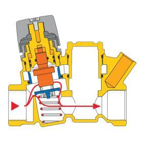
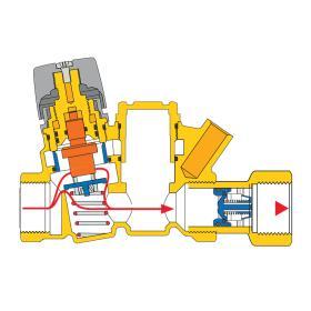
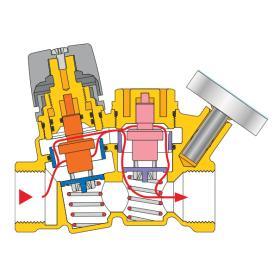
Figure 3-8 shows a cross section of the basic ThermoSetter™ valve, along with the flow path through the valve when the balancing element allows maximum flow. When operating in this mode, the valve’s Cv value is 2.1 (e.g., a flow rate of 2.1 gpm of water creates a 1 psi pressure drop across the valve).
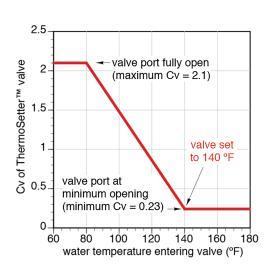
Figure 3-9 shows how the Cv value of the ThermoSetter™ valve changes based on entering water temperature, and for a valve that has been set for 140ºF.
At entering water temperatures of approximately 80ºF or less, the flow passage through the ThermoSetter™ is fully open, and the valve operates at its maximum Cv of 2.1. If the water entering the valve increases above 80ºF, the thermostatic element within the valve begins to reduce the flow passage, causing the valve’s Cv to decrease. If the entering water temperature climbs to 140ºF or higher, the flow passage reaches its minimum opening position, and the valve operates at its minimum Cv of 0.23. This allows minimal but sufficient hot water flow through the valve to ensure it can continuously sense entering water temperature.
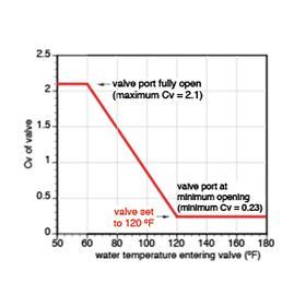
If the valve’s knob is rotated to a lower setting, the sloping portion of the red line seen in Figure 3-9 slides to the left, as shown in Figure 3-10, where the valve’s setting is now 120ºF.
The valve maintains the same maximum and minimum Cv values, and the same nominal 60ºF proportional range between these Cv values. The only change is the temperature at which the minimum Cv is achieved.
Figure 3-11 shows the basic ThermoSetter™ valve with the optional check valve assembly installed on the outlet side.
The check valve prevents flow reversal through the recirculation piping in a multi-branch DHW distribution system, which can occur due to pressure differentials caused by highly variable DHW demands. Each branch in a multi-branch recirculation system must include a check valve. The check valve option offered for the ThermoSetter™ reduces installation time compared to installing a separate external check valve.
THERMOSTATIC DISINFECTION OPERATION
Readers examining Figures 3-8 and 3-11b are likely wondering about the chamber to the right of the valve’s thermostatic element. What is its purpose?
This chamber allows the ThermoSetter™ to be further configured for DHW recirculation systems that incorporate automatic disinfection cycles.
A typical thermal disinfection cycle causes the water entering the DHW distribution system to rise to an elevated temperature sufficient to quickly kill pathogens such as Legionella bacteria. Although specific standards and code requirements vary, a typical thermal disinfection cycle causes the hot water entering the DHW distribution system to reach the following temperatures for the specific time, on a once-per-24-hour basis:
158ºF (70ºC) for 10 minutes
149ºF (65ºC) for 15 minutes
140ºF (60ºC) for 30 minutes
These temperature/duration combinations apply to the farthest fixture in any branch of the recirculating systems. The first two require temperatures that are higher than the maximum setting of the thermostatic balancing element in the ThermoSetter™ valve. Thus, ThermoSetter™ valves with only a thermostatic balancing element are not suitable for use in systems that employ thermal disinfection cycles. However, the ThermoSetter™ valve can be further configured for use in systems that employ thermal disinfection.
Figure 3-12 shows a ThermoSetter™ valve with a second thermostatic element mounted in the valve’s downstream chamber. It also shows the optional thermometer inserted into a dry well at the valve’s outlet. This thermometer indicates the water temperature leaving the valve.
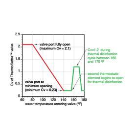
The second thermostatic element allows flow to pass through the upstream thermostatic balancing element, while the latter operates over its normal range of temperature. However, if the entering water temperature reaches approximately 155ºF, as it would at the beginning of a thermal disinfection cycle, the second thermostatic element begins to open. As this occurs, a parallel flow passage within the valve causes the valve’s Cv to increase from its minimum of 0.23 at an entering water temperature of 155ºF to a Cv of 1.2 at an entering water temperature of 160ºF, as shown in Figure 3-13.
The increased Cv value allows increased flow of high temperature water through the valve during the thermal disinfection cycle. When the entering water temperature reaches 170ºF, the second thermostatic element begins to reduce its Cv, and hence reduce flow through the valve. The Cv value decreases back to its minimum value of 0.23 if the entering water temperature reaches approximately 175ºF or higher. Reducing the Cv under these conditions allows thermal balancing between the branches of the system. It also allows a variable-speed recirculation circulator to reduce electrical input power when the water temperature entering the ThermoSetter™ valve is sustained above the water temperature needed for thermal disinfection. At the completion of the thermal disinfection cycle, the water temperature entering the valve decreases, and the valve returns to its normal operation with the second thermostatic element closing the bypass opening, returning flow control to the upstream thermostatic element.
ACTUATOR-CONTROLLED DISINFECTION
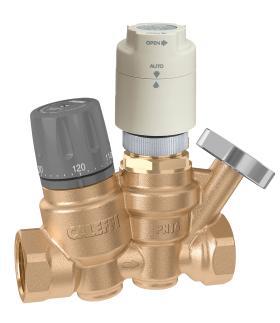
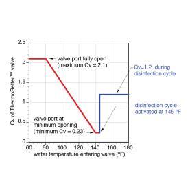
In some recirculating DHW systems, disinfection is accomplished using methods such as periodically injecting chemicals into the system, or irradiating the water with ultraviolet light. These methods are controlled by an automation system. They don’t necessarily require the same elevated water temperatures used with thermal disinfection, but they do require similar flow rates. To accommodate these methods, the ThermoSetter™ valve can be equipped with an electrically-actuated secondary valve cartridge rather than a second thermostatic element. A ThermoSetter™ valve equipped with a low voltage electric actuator is shown in Figure 3-14.
This version of the ThermoSetter™ includes a spring-loaded valve cartridge in the downstream chamber. An internal spring holds this valve in the open position. When the actuator is fastened to the ThermoSetter™ body, this spring is compressed and the valve disc positioned so that flow will pass through the upstream balancing element in the normal manner. When the actuator is powered on by 24 VAC, it retracts its stem, allowing the downstream valve to open such that the flow coefficient through the valve stabilizes at 1.2. The valve remains at this disinfection Cv value as long as the actuator is energized. When power is removed from the actuator, the valve returns to normal thermal balancing operation.
Figure 3-15 shows the flow characteristics of a ThermoSetter™ valve with actuator-controlled disinfection taking effect at 145ºF.
Actuator-control of ThermoSetter™ valves allows options that are not available with thermostatic-based disinfection. For example, in a multi-branch system, any ThermoSetter™ valve equipped with an actuator can be controlled independently. This allows for different disinfection cycle times or frequencies in specific portions of the system. It also allows any valve to coordinate with other hardware in the system such as chemical injectors or ultraviolet water sanitizers.
The dry well at the outlet of the ThermoSetter™ valve can be equipped with a temperature sensor (rather than a thermometer). That sensor can provide the outlet temperature of the valve to the controls for a system using thermal disinfection, and thus be used to verify that suitable disinfection actions have occurred in each branch of the system.
When designing a recirculation system, the suggested Cv value for a ThermoSetter™ valve is 0.52. This corresponds to how the valve would operate in a system with an allowed DHW temperature drop of 10ºF between the heat source and the farthest fixture.

