INTRODUCTION
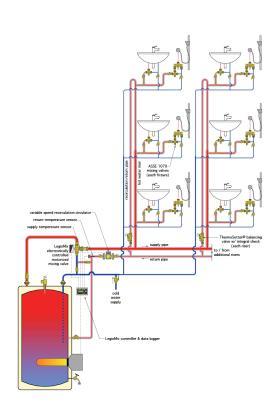
This section combines all these previously discussed concepts into a state-of-the-art DHW delivery system. Figure 4-1 shows one example of such a system.
idronics #21 also described the advantages of recirculating domestic hot water systems and how to properly balance them using thermal balancing valves.
This system uses a point-of-distribution motorized mixing valve and its associated controller. The valve and controller have two operating modes:
• Normal mixing mode, during which the valve maintains a preset outlet temperature, such as 125ºF to the DHW recirculation loop.
• Thermal disinfection mode, during which the valve allows the water temperature leaving the valve to rise to 165ºF for a minimum of 30 minutes. During this time the valve also monitors the water temperature at the return end of the recirculation loop. A successful thermal disinfection cycle is determined by verifying that the return water temperature has been maintained at no less than 140ºF for a minimum of 30 minutes.
The normal mixing mode provides an acceptable delivered water temperature to the fixtures served by the system. Each of these fixtures is equipped with an ASSE 1070 point-of-use thermostatic mixing valve that reduces the water temperature delivered to the fixture to 110ºF, and thus, protects against burns under all system operating modes (e.g., both normal and thermal disinfection mode).
The water temperature maintained during the normal mixing mode reduces piping heat loss relative to the losses that would result from higher loop temperatures. This reduces the energy required for system operation. It also reduces heat gain within the building that contributes to cooling load.
The hot water leaving the motorized mixing valve supplies a recirculation loop. Flow in this loop is driven by a small variable-speed high-efficiency stainless steel circulator. The flow rate in the main portion of the loop, as well as through the two hot water risers and recirculation return piping, has been determined so that the temperature at the farthest fixture served by each riser is no more than 5ºF lower than the water temperature leaving the mixing valve.
The calculations necessary to determine these flow rates are presented in idronics #21.
THERMAL BALANCING
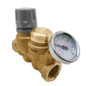
The recirculation return riser in each of the two riser groups is equipped with a Caleffi ThermoSetter™ thermal balancing valve. An example of such a valve is shown in Figure 4-2.
Thermal balancing valves are discussed in detail in idronics #21
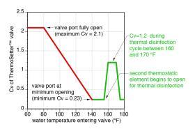
This valve contains two independent thermostatic elements. The primary element has an adjustable temperature setting. As the water temperature passing into this valve rises toward its setting, the primary thermostatic element throttles the valve to a minimum flow coefficient (e.g., Cv) of 0.23. At that condition, the valve only permits minimal flow of water through the return piping. The flow that does pass through is sufficient to allow the valve to continuously sense water temperature.
If the temperature sensed by the thermal balancing valve decreases, the Cv of the valve increases. At a temperature of 60ºF below the setpoint, the Cv of the valve is 2.1. Higher Cv values allow increased flow rate through the valve, which in turn allows higher recirculation flow through the riser group. Those higher flow rates compensate for decreasing water temperature in the riser group that could be caused by piping heat loss under low DHW demand conditions.
The varying Cv of the thermal balancing valve reduces recirculation flow in the DHW riser group when the water temperature through that riser group is sufficient to ensure adequate DHW delivery temperature to the farthest fixtures served by that group. Conversely, when the water temperature entering the thermal balancing valve decreases, which is likely the result of piping heat loss under low-demand conditions, the increasing Cv allows greater flow through the riser group.
By reducing its Cv as the entering water temperature approaches the valve’s setpoint, the valve reduces the recirculation flow rate in the portion of the system served by the associated riser group. The variable-speed recirculation circulator “interprets” this flow reduction as an attempt to increase differential pressure between the circulator’s inlet and outlet ports. It responds by reducing motor speed to maintain the necessary differential pressure. Reduced motor speed reduces the electrical power input to the circulator. Electrical energy savings associated with variable-flow recirculation DHW systems can be substantial, especially in larger commercial or institutional applications.
Thus, the combination of thermal balancing valves on the recirculation return of each riser group, along with a variable-speed recirculation circulator, ensures adequate (but not excessive) recirculation flow in all portions of the system, while minimizing the power required to operate the recirculation circulator.
When the motorized point-of-distribution mixing valve enters the thermal disinfection mode, the water temperature passing through the recirculating portions of the system increases to 165ºF at the outlet of the valve, and approximately 160ºF at the farthest fixture served by each riser group.
When the water temperature entering the thermal balancing valve increases above 155ºF, the ThermoSetter™ valve’s second thermostatic element reacts by bypassing flow around the primary thermostatic element and increasing the valve’s Cv from 0.23 to 1.2, which corresponds to an inlet temperature of 160ºF. The increased Cv allows for higher flow rates through the recirculation system during the thermal disinfection cycle. Higher flow rates reduce the temperature drop through the piping circuits, and help ensure that adequate disinfection temperatures are achieved in all portions of the recirculation system. When the thermal disinfection cycle ends and water temperature decreases, the thermal balancing valve returns control to the primary thermostatic element. Figure 4-3 shows how the Cv of a Caleffi ThermoSetter™ valve, when adjusted to a setpoint of 140ºF, varies between normal recirculation mode and thermal disinfection mode.
There are many potential variations of the schematic shown in Figure 4-1. For example, each fixture group could be different, having more or less fixtures requiring DHW. What would remain unchanged is the concept of minimizing the dead leg piping within each fixture group.
There could also be more riser groups within the system. What would remain unchanged is the presence of a thermal balancing valve with integral check valve within each of the recirculation return piping paths.
There could also be multiple motorized mixing valves, configured in parallel for high flow applications that are beyond the flow capacity of the largest available valve body.
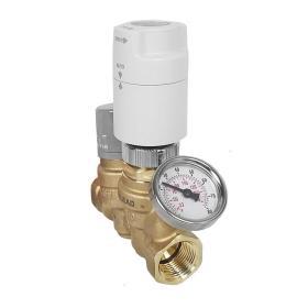
Yet another variation would be the use of low-voltage valve actuators on each of the thermal balancing valves that are wired to a building automation system. These actuators replace the function of the previously described thermal disinfection thermostatic element. The building automation system could be programmed to power these actuators to create specific thermal disinfection start times and durations for each riser group. These thermal disinfection cycles would be coordinated, through the building automation system with the controller operating the motorized mixing valve.
Figure 4-4 shows an example of a ThermoSetter™ valve equipped with a low-voltage valve actuator.
The ThermoSetter™ balancing valves could also be equipped with temperature sensors, rather than dial thermometers, to provide a building automation system with temperatures at the return of each recirculation riser group. Those temperatures could be recorded to verify successful completion of each thermal disinfection cycle, based on maintaining the return end of each riser group at a specific temperature for a specific minimum time.


