The previous section discussed the need for multiple water temperatures to provide both burn protection and Legionella control in domestic hot water systems. This section describes specific hardware to establish and maintain those temperatures.
WATER HEATER TEMPERATURE CONTROLS
The most common device used to create domestic hot water in North American homes is a tank-type heater supplied by electricity, natural gas, propane or fuel oil. Some recently released tank-type water heaters also have integral heat pumps that gather heat from air surrounding the tank, increase the temperature of that heat, and release it into domestic water inside the tank.
There is also an assortment of “tankless” water heaters that operate on electricity, natural gas or propane. They are designed to add heat to domestic water as soon as the heater detects a sufficient minimum flow rate caused by a draw at a fixture or appliance within the building.
All these devices contain internal thermostatic controls. Some are very simple bimetal thermostatic elements that snap the electrical contacts necessary to operate the heater closed at some temperature and open at a higher temperature. Others use solid-state temperature sensors wired to electronic controllers.
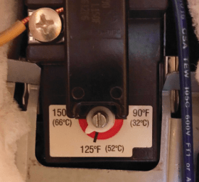
Although these devices meet the standards necessary to legally sell the water heater in North America (UL, CSA, etc.), many do not provide precise control of the water temperature leaving the heater. Some thermostats used on electric water heaters have printed temperatures on their adjustment dial, others simply indicate high, medium or low settings.
The thermostats used on tank-type water heaters also cannot compensate for incoming water temperatures that are higher than their setting, such as might be the case for water supplied from a solar thermal “preheating” system, or the coil in a thermal storage tank heated by a biomass boiler. The limited accuracy and inability to prevent potentially high-temperature water within the tank suggest that tank controls should not be the sole means of regulating the water temperature delivered to domestic hot water distribution systems.
THERMOSTATIC POINT-OF-DISTRIBUTION MIXING VALVES
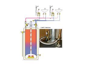
To ensure accurate control of domestic water temperature leaving a water heater, a thermostatic mixing device conforming to ASSE standard 1017 can be installed between the water heater and DHW distribution piping. One simple method for providing such a valve on a tank-type water heater is shown in Figure 3-2.
In this system, which does not have downstream devices to further reduce water temperature, the outlet temperature from the thermostatic mixing valve would typically not be set above 120ºF. Even lower outlet temperature settings such as 110ºF may be required in some circumstances.
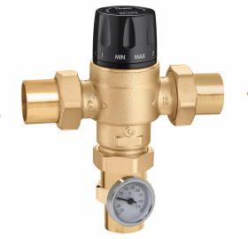
Thermostatic mixing valves conforming to ASSE 1017 are also available in larger sizes and with several types of piping connections, including NPT treads, soldered, press and PEX crimp.
The use of ASSE 1017 point-of-distribution mixing valves or 2-stage mixing assemblies by themselves does nothing to prevent water stagnation in portions of the system that experience minimal draws of DHW. However, a system using an ASSE 1017 point-of-distribution mixing valve can be further detailed to reduce the potential for stagnant water.
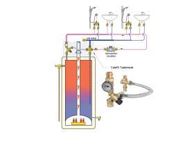
Figure 3-5 shows how the system from Figure 3-2 can be modified to include a recirculation loop.
A small stainless steel or bronze circulator has been added to the system, along with piping that carries domestic hot water that has reached the farthest fixture back to the water heater. The same Caleffi TankMixer assembly shown in Figure 3-2 can be used in this application. The cap that covered the side port of the cold water fitting as shown in Figure 3-2 is removed, and the recirculation pipe is connected to this port.
Recirculation ensures that water at the desired temperature is immediately available at all fixtures or appliances served by the plumbing system. It also reduces the potential locations where Legionella bacteria could multiply relative to non-recirculating systems.
THERMOSTATIC POINT-OF-USE MIXING VALVES
When point-of-distribution mixing valves or 2-stage mixing assemblies are set to temperatures that prevent scalding (typically 110 to 120ºF), they allow domestic hot water to pass throughout the distribution system at temperatures that do not effectively kill Legionella bacteria.
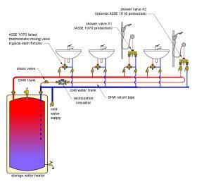
If Legionella disinfection is desired (or required), the tank-type water heater could be operated at a minimum temperature of 140ºF, along with installation of “point-of-use” thermostatic mixing valves conforming to ASSE standard 1070 at each fixture that doesn’t have internal anti-scald protection. The concept is shown in Figure 3-6.
Four of the five fixtures in Figure 3-6 have ASSE 1070 anti-scald mixing valves installed in close proximity to the fixture. The shower valve at the far right of the system has an internal temperature compensating mechanism conforming to ASSE 1016, and as such does not require an ASSE 1070 mixing valve.
This system allows the water heater to be maintained at a temperature of 140ºF or higher to effectively kill Legionella bacteria carried into the heater with cold water. It also allows each fixture to receive a reduced water temperature, typically in the range of 110 to 120ºF, depending on facility type and applicable regulations. The recirculation detail ensures immediate hot water availability and reduces the potential for stagnant water in the system.
All hot water supply and recirculation piping should be insulated to minimize heat loss.
idronics 21 presents methods and data for determining heat loss from bare and insulated copper tubing used in recirculating DHW systems.
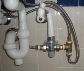
Point -of-use thermostatic mixing valves listed to the ASSE 1070 standard should be installed close to the fixture from which hot water will be drawn. A typical installation beneath a lavatory is shown in Figure 3-7.
Keeping the point-of-use mixing valve close to the fixture reduces the amount of piping that operates at lower (safe delivery) temperatures that could support growth of Legionella bacteria.
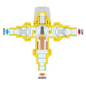
Thermostatic mixing valves continuously adjust the proportions of entering hot and cold water so that the mixed water stream leaving the valve remains at a set temperature. This regulation is created by the movement of a non-electric thermostatic element within the valve, as shown in Figure 3-8.
The thermostatic element contains a special wax that expands and contracts with temperature changes. This element is fully immersed in the mixed-flow stream leaving the valve, and thus, it continually reacts to changing inlet temperatures and flow rates.
The thermostatic element adjusts the open area of the ports that allow hot water and cold water to enter the valve. As the open area of the hot water inlet port decreases, the open area of the cold water inlet passage increases, and vice versa. If the temperature or pressure at either inlet port changes, the valve quickly and automatically compensates to maintain the set outlet temperature.
Thermostatic mixing valves listed under the ASSE 1070 standard are also pressure compensated. If cold water flow to the valve is interrupted, the valve must immediately reduce the flow of hot water leaving the valve to a small percentage of normal flow. The action requires a minimum temperature difference of 18ºF (10ºC) between the hot water inlet and mixed water outlet. Valves listed to the ASSE 1070 standard must also have internal check valves in both inlet ports.
MOTORIZED MIXING VALVES
Although thermostatic mixing valves have long been the standard for point-of-distribution temperature control in domestic water systems, motorized mixing valves operated by dedicated-purpose electronic controllers are now available. These controllers provide functionality that’s not possible with thermostatic valves. Examples of this added functionality include:
• Ability to operate the valve over a very wide range of temperatures, as well as a wide range of temperature differences between entering hot and cold water.
Precise temperature control based on electronic temperature sensing at one or two locations in the system.
• Ability to execute several variations of thermal disinfection cycles involving different water temperatures and durations, and also log the temperatures that have been established during those cycles.
• Ability to connect the controller to a building automation system, allowing the building operator to monitor and change settings without having to be at the valve’s physical location.
• Ability to automatically adjust flow proportions to maintain the necessary outlet temperature, while experiencing pressure variations on the hot and cold water inlet ports due to other demands in the system.
• Lower pressure drop than thermostatic mixing valves.
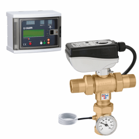
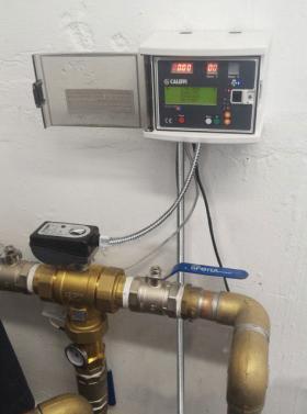
Figure 3-9 shows an example of a motorized mixing valve and its associated controller specifically designed to provide central water temperature control in DHW systems.
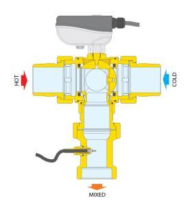
Figure 3-10 shows the internal construction of this valve.
This valve uses a rotating ball to control the proportions of entering hot and cold (or warm) water. The ball is rotated by the motorized actuator at the top of the valve. The mixed flow then passes a temperature sensor, which provides the controller with continuous feedback of leaving water temperature.
The Caleffi LEGIOMIX® motorized mixing valve and its associated controller can be configured for several operating modes. It can operate to maintain a set outlet temperature, while also recording the water temperature on the return side of the recirculation loop. It can initiate a thermal disinfection cycle controlling both the recirculation circulator and water temperature from the heat source during that cycle. It also records the times and temperatures achieved within the system (supply and return) for each day.
Alarms can be issued if the programmed thermal disinfection cycle is not successfully completed, (i.e., if the supply or return temperatures drop below their programmed setpoints). The controller can also interface with building automation systems using ModBus or BACnet protocols. More detailed information on the valve’s capabilities is given in the product pages at the end of this issue.
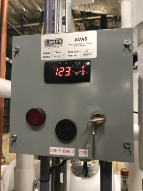
Designers should note that some regulations require specific safety controls on DHW systems. These controls must provide a fail safe shut off of the hot water supply to the central mixing valve if the temperature leaving that valve exceeds the valve’s setpoint by a specific value, such as 10 ºF. The system must also provide a visual and audible alarm, and only allow a manual reset of a detected fault condition. Figure 3-11 shows an example of such a controller.
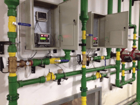
Caleffi LEGIOMIX® valves can also be used in parallel piping configurations to accommodate higher flow requirements, as shown in Figure 3-12.
Section 4 will show how motorized mixing valves can be applied, along with thermal balancing valves and recirculation, to create state-of-the-art DHW delivery systems.


