PREFACE
Many of the principals for designing a single-loop DHW recirculation system that were discussed in Section 2 also apply to systems with multiple branches. These include the concept of providing a minimal acceptable DHW supply temperature at the farthest fixtures, evaluating piping heat loss, and estimating the recirculation flow rate and associated head loss of the system so that a suitable circulator can be selected.
However, unlike in a single-loop system, flow balancing is necessary to ensure adequate but not excessive flow through each branch of the system. This section discusses the specifics for a multi-branch system using ThermoSetter™ valves.
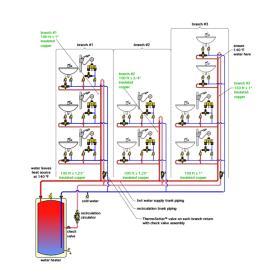
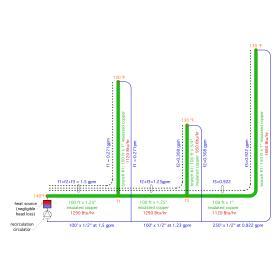
Figure 4-1 shows a multiple-branch DHW recirculation system. The system consists of 3 branches, each with multiple fixture groups. Each fixture is protected against high delivery temperature by an ASSE 1070 thermostatic mixing valve. These valves are set to deliver 110ºF water to their fixtures. To prevent Legionella growth, water leaves the heat source at 140ºF. The designer needs to ensure that the minimum water temperature reaching the hot port of the thermostatic mixing valve at the farthest fixture is 130ºF. Each branch of the system includes a Caleffi ThermoSetter™ balancing valve.
The designer needs to determine the necessary recirculation flow rates in each branch, the total recirculation flow rate and the head requirement for the recirculation circulator.
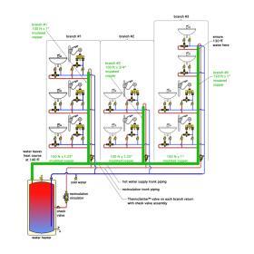
The first step in the process is to estimate the heat loss of the piping to the farthest fixture in each branch. These piping segments are identified with green overlays in Figure 4-2. Each major segment of the hot water supply piping is identified for length and pipe size. All piping is assumed to be covered with 1/2“ wall thickness elastomeric foam insulation.
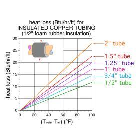
The heat loss of each piping segment can therefore be estimated using Figure 2-10b (repeated as Figure 4-3.)
Since water leaves the heat source at 140ºF, and must be no less than 130ºF at the farthest fixture in each branch, the average water temperature in the system is 135ºF. This is the temperature that will be used to estimate piping heat loss. Assume the air temperature surrounding the piping is 70ºF. Thus, the ∆T value for the horizontal axis of Figure 4-3 will be 135ºF - 70ºF = 65ºF. The heat loss per foot of piping for the 3 pipe sizes involved are as follows:
• 3/4” insulated copper tubing: 9.5 Btu/hr/ft
• 1” insulated copper tubing: 11.2 Btu/hr/ft
• 1.25” insulated copper tubing: 12.9 Btu/hr/ft
Using these values, the total heat loss of all the hot water supply piping is approximately:
(200 ft x 12.9 Btu/hr/ft) + (350 ft x 11.2 Btu/hr/ft) + (100 ft x 9.5 Btu/hr/ft) = 7,450 Btu/hr
The total recirculation flow rate to provide this total heat loss at a 10 ºF temperature drop can be calculated using Formula 4-1:
$$ f = \bigg({Q \over 500 \times \Delta T}\bigg)=\bigg({7450 \over 500 \times 10}\bigg) = 1.49 \approx 1.5gpm $$
Where:
$f$ = total recirculation flow rate (gpm)
$Q$ = total heat loss of supply piping (Btu/hr)
$\Delta T$ = temperature drop from heat source to farthest fixture (ºF)
Keep in mind that, while a flow rate of 1.5 gpm satisfies the thermodynamic requirement to provide the total heat loss of all supply piping based on a 10ºF drop, it doesn’t guarantee that the water temperature at the farthest fixture in each branch will not be more the 10ºF below the water temperature of the heat source. Finding the branch flow rate necessary to achieve the minimum temperature of 130ºF at the farthest fixture in each branch requires application of basic thermodynamics combined with some algebra. There is a need to generate multiple simultaneous formulas that govern the relationship between heat transfer, flow rate and temperature drop. These formulas are all based on variations of Formula 4-1, as well as recognizing that the flow entering a tee must equal the flow exiting that tee (e.g., conservation of mass).
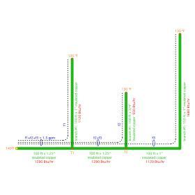
The formulas to be generated will have both known and unknown quantities. Figure 4-4 shows the unknown quantities (e.g., flow rates f1, f2, f3, and temperatures T1 and T2). It also shows the known quantities (e.g., total recirculation flow rate = 1.5 gpm, the estimated heat loss from the piping segments, and the 130ºF water temperature at the farthest fixture in each branch).
The flow rate in the first segment of the hot water supply trunk must be the sum of the three branch flow rates (f1+f2+f3). We have already determined this flow rate to be 1.5 gpm based on Formula 4-1 and the thermodynamics requirements of the entire supply piping system dissipating 7,450 Btu/hr while operating at a temperature drop of 10ºF.
Thus, we can write Formula 4-2:
Formula 4-2:
$$ f_1 + f_2 + f_3 = 1.5gpm $$
We also know the estimated heat loss from the first segment of the supply trunk to be 1,290 Btu/hr. Therefore the temperature at node T1 (marked as an orange square in Figure 4-4) can be calculated based on the necessary temperature drop at a flow rate of 1.5 gpm, and the heat loss of this first trunk segment:
Formula 4-3:
$$ T_1 = 140 - {1290 \over {500 \times 1.5}} = 138.28^o F $$
We also know the estimated heat loss of the riser in branch #1 to be 1,120 Btu/hr, as well as the temperature at the end of this branch to be 130ºF. Therefore, we can determine the necessary flow rate in this branch based on the heat dissipation and temperature drop:
Formula 4-4:
$$ f_1 = {1120 \over {500 \times (138.28-130)}} = 0.271gpm $$
This implies:
$$ (f_2 + f_3) = 1.5 - 0.2705 = 1.23gpm $$
The temperature at node T2 (also marked with an orange square in Figure 4-4) must correspond to the temperature drop, estimated heat loss and flow rate of the second segment of the supply trunk. We can write the relationship as Formula 4-5:
Formula 4-5:
$$ T_2 = 138.28 - {1290 \over {500 \times 1(f_2 + f_3)}} $$
But, since we know that (f2+f3) = 1.2295, we can substitute this number into Formula 4-5 and solve for T2.
$$ T_2 = 138.28 - {1290 \over {500 \times 1(f_2 + f_3)}} = 138.28 - {1290 \over {500 \times (1.2295)}} = 136.18^o F $$
Knowing temperature T2, we can solve for flow rate f2 based on the known heat loss of 950 Btu/hr along the riser of branch #2:
Formula 4-6:
$$ f_2 = {950 \over {500 \times (136.18 - 130)}} = 0.308gpm $$
The final step is to get flow rate f3 as follows:
$$ f_3 = 1.5 - f_1 - f_2 = 1.5 - 0.2705 - 0.3074 = 0.922gpm $$
To summarize, the branch flow rates needed to ensure 130ºF at the farthest fixture in each branch are:
branch #1 flow rate = 0.271 gpm
branch #2 flow rate = 0.308 gpm
branch #2 flow rate = 0.922 gpm
DETERMINING HEAD LOSS
Once the branch flow rates have been estimated, the next step is to determine the head loss of the most restrictive branch circuit path. In some systems, this will path will not be readily apparent. It will be necessary to calculate the head loss from the discharge port of the recirculation circulator to the inlet port of that circulator through each branch circuit path. This head loss should be calculated based on the flow rate within each segment of each branch, factoring in different pipe sizes and flow rates. Once these head losses have been individually determined, the largest head loss will be used to select the operating point of the recirculation circulator.
For the example system of Figure 4-1, in combination with the flow rates just determined, it is readily apparent that the circuit path through branch #3 will have the highest head loss. It has by far the longest piping run and needs to operate at a flow rate significantly higher than those of the other two branches.
The head loss through branch #3 can be determined based on the methods and data given in Appendix B. The head loss in smooth tubing is estimated using Formula B-1:
Formula B-1 (from Appendix B)
$$ H_L = (acl)f^{1.75} $$
Where:
$H_L$ = head loss of the piping segment (feet of head)
$a$ = fluid properties factor read from Figure B-1 in
Appendix B
$c$=pipe size factor read from figure B-2 in Appendix B
$l$ = pipe segment length (feet)
$f$ = flow rate (gpm)
Based on water at an average temperature of 135ºF, the “a” value for Formula B-1 in Appendix B is 0.048. The "c" values for Formula B-1, and for 1.25”, 1”, 3/4”, and 1/2” copper piping are as follows:
1.25” piping: c = 0.0068082
1” piping: c = 0.01776
3/4” piping: c = 0.061957
1/2” piping: c = 0.33352
The following piping segments are present in the circuit path through branch 3:
100 feet of 1.25" copper operating at 1.5 gpm
100 feet of 1.25" copper operating at 1.23 gpm
250 feet of 1" copper operating at 0.922 gpm
250 feet of 1/2" copper operating at 0.922 gpm
ThermoSetter™ valve with Cv = 0.52
100 feet of 1/2" copper operating at 1.23 gpm
100 feet of 1/2" copper operating at 1.5 gpm
Tank type water heater (negligible flow resistance)
The head loss for each piping segment within this flow path, and at the flow rate at which that piping segment operates, are as follows:
HL = (acl) f 1.75 = (0.048 × 0.0068082 ×100)(1.5)1.75 = 0.0664 ft
HL = (acl) f 1.75 = (0.048 × 0.0068082 ×100)(1.23)1.75 = 0.0469 ft
HL = (acl) f 1.75 = (0.048 × 0.01776 × 250)(0.922)1.75 = 0.1849 ft
HL = (acl) f 1.75 = (0.048 × 0.33352 × 250)(0.922)1.75 = 3.47 ft
HL = (acl) f 1.75 = (0.048 × 0.33352 ×100)(1.23)1.75 = 2.30 ft
HL = (acl) f 1.75 = (0.048 × 0.33352 ×100)(1.5)1.75 = 3.25 ft
The head loss through the ThermoSetter™ in branch #3 should be calculated based on a design Cv value of 0.52. It would be:
$$ H_L = 2.308 \bigg({f \over Cv}\bigg)^2 = 2.308 \bigg({0.9221 \over 0.52}\bigg)^2 = 7.26ft $$
The total estimated head loss of the piping in the circuit path through branch #3 is:
(0.0664 + 0.0469 + 0.1849 + 3.47 + 2.3 + 3.25) x 1.1 = 10.25 feet
The multiplying factor of 1.1 applied to this summation is a 10% added allowance to account for the head loss of fittings. The total estimated head loss is the head loss of the piping (10.25 feet) plus the head loss of the ThermoSetter™ valve (7.26 feet), which sums to 17.5 feet. The calculated
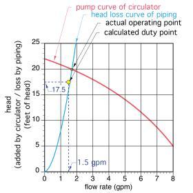
“duty point” of the circulator for this system is the total flow rate (1.5 gpm) combined with the total estimated head loss of 17.5 feet. The designer can now check pump curves for a circulator matching this requirement.
Figure 4-6 shows the calculated duty point along with the pump curve for a potential circulator. The pump curve passes slightly above the calculated duty
point of the recirculation system (e.g., 1.5 gpm @ 17.5 feet of head loss). This is generally acceptable. It will result in a flow rate slight higher than the duty point flow rate of 1.5 gpm. It’s worth noting that the majority of the head loss through the branch #3 circuit path is due to the 1/2” return piping. Changing some or all of the return piping to 3/4” size would substantially reduce this head loss, and thus allow a smaller recirculation circulator.If the piping in this example system had not been insulated, the heat loss from every piping segment would be significantly higher, and thus the recirculation flowrates would be higher.
These higher flow rates would also increase head losses (assuming that the pipe sizes did not change). High recirculation flow rates and higher head losses would likely require a larger circulator with a higher installation and operating cost.
Best practices for recirculating DHW delivery systems include insulation on all piping segments (supply and return). In some cases, a minimum specification for this insulation may be part of the local plumbing or mechanical code.


