All hydronic systems are governed by long-established and unchanging physical principles based on thermodynamics and fluid mechanics. Technicians who understand and apply these principles will often correctly identify underlying problems faster and more accurately than those who randomly guess about what’s wrong with the system.
THERMAL EQUILIBRIUM
All hydronic heating systems, regardless of size, complexity, materials used, etc., naturally seek to stabilize their operation at conditions where the rate of heat dissipation from the distribution system equals the rate of heat production at the heat source. This “balance” between the rates of heat production and heat dissipation is called thermal equilibrium.
The “evidence” that thermal equilibrium exists is stable water temperatures in all parts of the system. For example, the water temperature leaving the boiler might remain stable at 160 ºF, likewise, the water temperature entering the boiler may remain stable at 145 ºF. The water temperatures in all other parts of the system, regardless of their numerical values, also remain stable. Such stability only occurs when energy input is balanced with energy dissipation.
If not for the intervention of controls within the system, every system would eventually settle to a state of thermal equilibrium. That condition may or may not deliver proper heating to the building. It may or may not produce safe operating conditions. It may or may not allow the heat source to operate at optimal efficiency. Those important considerations “don’t matter” when a system is allowed to operate limited only by natural thermodynamic and fluid mechanics principles.
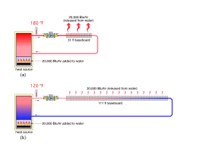
When asked about what controls the water temperature in a hydronic system, many people, including some heating professionals, respond that it’s the temperature setting of the controls within the heat source. That answer, while partially true, is also incomplete. The water temperatures in all parts of a system, supplied by a specific heat source, and operating under thermal equilibrium, also depends on the total surface area of all the active heat emitters in the system. This concept is illustrated in Figure 2-1.
Both of the simple hydronic heating systems shown in Figure 2-1 have the same heat source, which imparts heat to the circulating water at a rate of 20,000 Btu/hr. The system in Figure 2-1 (a) has 31 feet of residential fin-tube baseboard as a heat emitter. The system in Figure 2-1 (b) has 111 feet of the same baseboard.
Consider a situation where the heat source’s temperature controller in both systems is set very high, perhaps 200ºF, and the circulator in each system is operating at some nominal but realistic flow rate. Also assume that heat loss from the piping connecting the baseboard to the heat source is negligible.
The system in Figure 2-1 (a) will reach thermal equilibrium when the water temperature leaving the heat source is 180ºF. At that condition, the 31 feet of baseboard is dissipating 20,000 Btu/hr. In simple terms, there is no need for the water temperature in the system to climb to any higher, and it won’t - regardless of the 200 F setting on the heat source’s controller. The water temperature leaving the heat source will only increase to the value where thermal equilibrium is established. Understanding this response is important when diagnosing a system where the water temperature is not reaching the setting of the heat source’s temperature controller.
When the heat emitters are changed from 31 to 111 feet of baseboard, the system reaches thermal equilibrium when the water temperature leaving the heat source is 120ºF. The increased surface area of the heat emitters is solely responsible for this new operating condition. The fact that the heat source’s controller remains set at 200ºF is irrelevant. The water temperature in the system will not climb above 120ºF.
Most hydronic systems, especially older systems, or those with oversized heat sources, will not reach thermal equilibrium. After the heat source starts, the water temperature steadily climbs toward a thermal equilibrium condition, but the high limit controller on the heat source typically turns off further heat input before thermal equilibrium is achieved. This is especially true if the heat source’s heating capacity is oversized for the amount of heat emitter present. Assuming that the circulator continues to operate, the water temperature in the system decreases as heat is dissipated from the heat emitters into the space to be heated. When the water temperature has dropped through the operating differential of the controller, the heat source restarts and a similar cycle is likely to occur.
Multiple repetitions of this cycle are possible as long as the thermostat in the heated space continues to call for heat.
This cyclic operation of the heat source is very typical. In effect, it results in heat being added to the building in pulses, rather than as a continuous (e.g., steady) process. The rate of heat delivery is determined by the output rating of the heat source. The “on-time” of each heat delivery pulse is determined by the thermostat. The total heat added to the space during each pulse is approximately equal to the output rating of the heat source multiplied by the “on-time” of the heat source. The thermal mass of the system helps to “smooth out” this pulsed heat input effect, which often makes it less noticeable to occupants. Tens of thousands of North American hydronic heating systems operate this way, and in most cases, it is acceptable.
The fact that many systems don’t reach thermal equilibrium is good in the sense that it doesn’t allow the water in the system to climb to dangerously high temperatures. For example, if the heat source capacity in Figure 2-1 was doubled to 40,000 Btu/hr, and the same 31 feet of baseboard remained, the water temperature leaving the boiler would have to climb above 250ºF in order for the system to reach thermal equilibrium. While this condition is theoretically possible using a pressurized closed-loop system, it is risky from a safety standpoint. Water at that temperature will instantly flash to steam if the pressure is lost, and the result could be a devastating explosion. Although this modified system will consistently attempt to achieve thermal equilibrium, that attempt will be “cut short” by the system’s temperature limiting controllers.
The concept of thermal equilibrium helps designers and technicians understand what the system “wants to do.” It explains why some systems do not operate at the water temperature set on the heat source limit controller. It also implies what’s possible if the temperature limiting controls on the heat source failed, and thus, the justification for a secondary controller, such as a manual reset high limit.
HYDRAULIC EQUILIBRIUM
Just as all hydronic systems seek to operate with a balance between thermal energy input and thermal energy dissipation, they also seek to operate with a balance between mechanical energy input and dissipation. The mechanical energy input to the system's fluid is provided by one or more circulators. The mechanical energy dissipation is caused by friction between the moving fluid molecules, as well as between those molecules and the internal surfaces of components such as piping, valves and heat exchangers.
The mechanical energy imparted to the fluid in a hydronic system by a circulator is called “head.” The units for head energy are (ft•lb/lb). The unit of ft•lb (pronounced “foot pound”) is a unit of energy. As such, it can be converted to any other unit of energy, such as a Btu. Thus, head can be interpreted as the number of ft•lbs of mechanical energy imparted to each lb of fluid passing though the circulator. However, engineers long ago chose to cancel the units of pounds (lb) in the numerator and denominator of this ratio, and express head in the sole remaining unit of feet. To make a distinction between feet as a unit of distance and feet as a unit of fluid energy, the latter can be stated as feet of head.
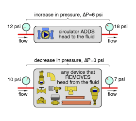
When head energy is added to or removed from a liquid in a closed-loop piping system, there will always be an associated change in the pressure of that fluid. Just as a change in temperature is “evidence” of a gain or loss of thermal energy, a change in pressure is evidence of a gain or loss in head energy. When head is lost, pressure decreases. When head is added, pressure increases. This concept is illustrated in Figure 2-2.
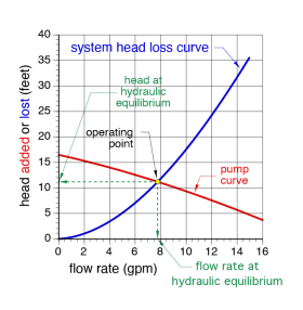
It’s possible to predict the flow rate that will develop when in a specific circulator is installed in a specific hydronic circuit. That flow rate will be such that the head energy added by the circulator is exactly the same as the head energy dissipated by the piping circuit. This condition is called “hydraulic equilibrium.”
The flow rate at hydraulic equilibrium is found by plotting the head loss curve of the hydronic circuit on the same graph as the pump curve for the circulator. An example of this is shown in Figure 2-3. The point where the head loss curve of the hydronic circuit crosses the pump curve of the circulator is called the “operating point.” This is where hydraulic equilibrium occurs. The flow rate in the circuit at hydraulic equilibrium is found by drawing a vertical line from the operating point down to the horizontal axis. The head input by the circulator (or head loss by the piping system) can be found by extending a horizontal line from the operating point to the vertical axis.
For more detailed information on hydraulic equilibrium, as well as system head curves and pump curves see:
All hydronic systems reach hydraulic equilibrium within a few seconds of a circulator starting. Flow rate increases during those initial seconds and stabilizes at a value that results in hydraulic equilibrium. Once established, the system will remain at the flow rate corresponding to hydraulic equilibrium unless something occurs that affects either the head loss curve or the pump curve.
Examples of what could change the circuit head loss curve include:
• The type of fluid in the circuit changes.
• The temperature of the fluid changes.
• Changes are made to the pipe type, pipe size or to the
components in the piping circuit.
• Valve settings are changed.
Examples of what could change the pump curve include:
• Change to a different circulator.
• Change the circulator to a different speed setting.
• Altering the circulator’s impeller.
Technicians who are troubleshooting flow-related issues in a hydronic system need to understand (and appreciate) the concept of hydraulic equilibrium. For example, if the flow rate is below some anticipated value, the head energy imparted by the circulator may be too low, or the head loss created by the system’s piping components may be too high, or both. Anything that decreases the head dissipation ability of the circuit, such as larger piping, short piping lengths, valves with higher Cv ratings, less fittings, etc., will typically shift hydraulic equilibrium to a higher flow rate, and vice versa.
STEADY STATE VS. TRANSIENT OPERATION
When hydronic systems are planned, and components in those systems are selected, it’s customary to assume a situation called “design conditions.” The building being heated is assumed to be surrounded by air at or very close to the coldest expected winter temperature, and thus the building’s heating load is at or very close to some maximum value, which is estimated based on heating load calculations. The hydronic system in the building is assumed to be operating continuously (e.g., steady state) to deliver heat to all conditioned spaces so that they are maintained at some specified air temperature.
That temperature is typically in the range of 68-72ºF for residential buildings or other buildings where humans are wearing “normal” winter clothing and participating in light activity, and 60-65ºF for industrial, shop or other types of buildings where occupants are more heavily clothed or working at higher activity levels. The heat source, circulators, heat emitters, piping and all other components in the system are selected under the possible (but unlikely) scenario that design load conditions could persist for days on end, until the outdoor temperature eventually moderates. The underlying goal is to prevent uncomfortable conditions regardless of the duration of design load conditions.
While this design approach is “conservative” in one sense, it’s also unrealistic in terms of how a hydronic system operates during the majority of a typical heating season. Systems that have components sized and selected to handle design load conditions will not operate continuously over most of the heating system when heating loads are less (often far less) than design load values. Instead, most of the devices in the system will turn on and off several times every day, and sometimes several times every hour, to prevent overheating during partial load conditions. This behavior is called “transient” system operation.
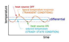
If a technician happened to measure the water temperature at the instant the burner turned off, that temperature would only exist for a moment. A few seconds later, the temperature could be slightly higher due to control overshoot. A few more seconds later, the temperature would be less as heat is dissipated from the water. The simple graph in Figure 2-4 doesn’t show what are likely to be even more complex transient temperature variations caused by longer periods when the boiler is off, or sudden changes in boiler temperature when a cold zone circuit first activates.
Under common transient conditions, the water temperature leaving a heat source will change almost continuously, and flow rates in various portions of the system might also change as different zone circuits turn on and off, or valves modulate. Figure 2-4 illustrates a typical transient boiler water temperature versus time graph, compared to a (theoretical) steady state temperature condition. The boiler fires when its leaving water temperature has dropped slightly below some setpoint temperature (represented by the green dots). The boiler turns off when its leaving water temperature is slightly above this setpoint (represented by the red dots).
In a theoretically “ideal” system, the water temperature leaving the boiler would remain perfectly stable at the setpoint value as time elapses. This would be a true steady state condition. In a “real” system, the boiler’s leaving water temperature is usually increasing and decreasing based on the differential setting of the boiler’s temperature controller. Over several firing cycles, and assuming that heat dissipation by the load is stable, the average water temperature leaving the boiler should be close to the value represented by the steady state line.
A technician who is troubleshooting a system that is operating under transient conditions needs to realize that the temperatures, flow rates, electrical currents, etc., that they read from instruments at some moment in time are just a “snapshot” of overall system operation, and may or may not point to a problem. For example, if the high limit controller on a heat source is set for 180ºF, and the measured water temperature leaving the heat source at some moment is 140ºF, that difference doesn’t necessarily mean that “something is wrong” with the heat source. Perhaps the heat source was just turned on from being off for several hours. Or maybe a zone circuit just turned on and a slug of cool water just entered the heat source.
Hydronic systems are typically “moving targets” in terms of acquiring performance data that’s to be used to determine what changes or service procedures need to be made. Technicians need to be careful about drawing rapid conclusions based on observing a system operated for only one or two minutes. In some systems, several minutes of observation may be necessary to determine if all the intended coordination of devices is occurring.

