Fundamentally, troubleshooting a hydronic heating system is a matter of verifying that processes are occurring in a pre-established sequence, and in an expected manner, starting at the fuel supply and tracing the process all the way to the level of comfort present in the building. This section follows this sequence step by step and explores common issues.
PREFACE
All modern hydronic heating systems provide 3 basic functions:
1. Converting the chemical energy in a fuel (or electrical energy) into heat and imparting that heat to water or to a water-based fluid. Boilers of many different configurations and sizes are the component where this conversion occurs.
2. Converting electric energy into mechanical energy called head and imparting that energy to the system’s fluid. The circulators in a hydronic system enable this conversion process.
3. Transporting a fluid that now contains both thermal and mechanical energy to where that energy is needed to maintain comfort in a building.
Hydronic cooling systems have similar energy flows, only from the conditioned space back to the device providing the chilled water.
Fundamentally, troubleshooting a hydronic heating system is a matter of verifying that these processes are occurring, in a pre-established sequence, and in an expected manner, starting at the fuel supply and tracing the process all the way to the level of comfort present in the building. The root cause of a performance issue is often discovered when one of the steps in the planned flow of energy from source to end use is interrupted or impaired. That interruption or impairment could be caused by a physical failure of some component, or by improper selection, installation, maintenance or adjustment of a component.
When the underlying cause of a problem is not “obvious,” it’s important to maintain a sequential approach to troubleshooting, rather than taking random guesses as to what might be causing the problem. For example, it makes no sense to remove and replace a circulator that’s not working as expected, only to later find out that the thermostat controlling that circulator had dead batteries, or has been unintentionally turned off. There’s little doubt that such random approaches to troubleshooting have occurred and continue to occur. Even if the underlying problem is eventually discovered and corrected, the time and expense associated with needless “tinkering” with the system frustrates all those involved.
In some cases, the cause of improper operation is immediately apparent. For example, if the technician walks into a mechanical room and water is spraying out of the side of a boiler or from some other component, it’s obvious that at least that component is not in a normal state. Likewise, any trace of smoke or burning odor coming from an electrical component is not normal and implies service is necessary — perhaps immediately.
These abnormal situations are often the easiest to diagnose and correct. In some cases, they are caused by a failure of the component due to manufacturing defects. In other cases, the underlying cause of the failure is due to improper application, lack of maintenance, improper adjustment, uncontrollable external conditions such as electrical voltage spikes, brownouts, or even vermin chewing on piping, insulation or wiring. Troubleshooting becomes more challenging in situations where the underlying problem is not obvious. Perhaps the owner states that the temperature in one bedroom seems to fluctuate but under no apparent recurring pattern. Another complaint might be that some “weird noise” occasionally seems to come from the mechanical room. Still another would be that the system’s pressure relief valve drips water on every cold winter morning but is otherwise fine. The steps that follow are meant to guide a reasonably competent technician who is trying to correct an issue with a typical zoned hydronic heating system with which they have no previous experience.
STEP 1: Learn what the system is supposed to do and how it is operated by the occupants. Ask questions.
This initial step is important and often overlooked. It makes no sense to try to correct what someone might perceive as a problem, when the system is actually performing just as its designer intended. For example, a complaint might be that some spaces in a building cool slightly below their set comfort level at some repeatable times in morning and early evening but are otherwise fine.
The underlying cause could be an indirect water heater that has been configured as the “priority” load in the system. When a call for domestic water heating occurs, all space-heating zones are temporarily and automatically turned off, in some cases for up to 30 minutes, by the system’s controller(s). The lack of heat input during that time might allow some spaces to cool slightly below normal. Be that as it may, the system is performing as intended, at least based on the settings made by the last person to configure the system’s controls. If that performance is unacceptable to the owner, a simple setting change on a controller could correct the issue. When first examining an unfamiliar system, technicians should also ask the building owner or maintenance personnel if there is documentation for the system.
For more detailed information on documenting hydronic systems, see: idronics #20
Did the designer or installer create a piping and electrical schematic? Did the installer create a sequence of operation for the system? Are there installation and operation (I/O) manuals for the major components, perhaps organized into a binder in the mechanical room? This type of documentation can help quickly clarify the intended operation of the system. It’s also important to ask the building occupants how they operate and maintain the system. Don’t make assumptions.
Some possible inquiries include:
• Do they use thermostat setbacks at night or for other extended periods? What type of temperature/ time programming do they use with their programable thermostats?
• Do they use large amounts of domestic hot water at certain times of the day that might coincide with a drop in space-heating comfort?
• Do they run ventilation fans or open windows for fresh air during winter?
• What type of routine maintenance do they perform (or have others perform) on the system? Are there records of that maintenance and who performed it?
• If a garage is occasionally heated by the system that also heats the house, how often is it heated, and to what temperature?
• Have any carbon monoxide or smoke detectors in the vicinity of the mechanical room ever sounded an alarm?
• Have there been any recent power outages, voltage spikes, brownouts, loss of building water pressure, seismic events or close thunderstorms prior to a problem developing with the system?
• Has anyone other than the owner or occupant had access to the mechanical room?
• Have there been any recent modifications to the system?
• Have any chemicals been added to the water in the system?
• Have there been any paints, pool chemicals, laundry detergents/bleaches or other chemicals stored in the mechanical room.
• Have they seen, heard or smelled anything unusual as the system operates, such as water on the floor, error codes on displays, abnormal sounds or odors associated with fuel, flue gases or electrical overloads?
Few building owners would intentionally avoid disclosing information that might lead to the underlying cause of problems with their system. However, many don’t realize that something that they may have observed could be the underlying cause. The more information the technician can gather “up front,” the faster they are likely to zero in on the cause of the problem.
STEP 2: Write down or otherwise record all current controller settings.
In some situations, a performance issue can be partially or fully resolved by changing one or more settings on system controllers. However, making random adjustments to controller settings can quickly lead to problems, especially if the original settings need to be restored and the person making the adjustments doesn’t remember what those settings were.
To avoid this problem technicians should take the time to write down or otherwise record all controller settings “as found.” Furthermore, any changes to a controller setting should be documented with the “as found” setting, date the setting was changed, who changed the setting, and the revised setting. Technicians should also record the “as found” pressures and temperatures for the system. The troubleshooting steps that follow should also be considered before making adjustments to controller settings.
STEP 3. Verify that electrical power and fuel are available to the system.
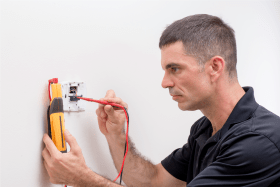
This step helps to eliminate the possibility that the problem is lack of available fuel or electricity to operate the system. Verify that fuel oil, natural gas, propane, electricity or other fuel is available at the heat source. Is there fuel in any associated storage tank? Are all fuel shutoff valves open? Are all associated electrical circuit breakers or disconnects closed? Keep in mind that a closed circuit breaker or disconnect is not a guarantee that electrical power is available at the heat source. Use a multimeter to verify that line voltage is available at the power input terminals of the heat source. If it’s not, work backward on the electrical supply circuit to find the issue.
STEP 4. Verify that all thermostats are functioning properly.
Most heating and cooling thermostats operate on 24 VAC. They enable the heat source to operate. They also “call” for their associated zone to operate.
Verify that the thermostat being tested is set to heat mode. If the thermostat uses batteries, verify that the low battery indicator is not on. If the thermostat has multiple time/ temperature settings, adjust it to temporarily override those settings. Adjust the temperature setting to a high “test temperature” of 80 F or more to ensure that it should be calling for heating operation.
STEP 5. Verify that the heat source is enabled to operate whenever one or more zone thermostats are calling for heat.
Most hydronic heat sources are enabled to operate when electricity can pass through an external circuit connected to two terminals on the heat source. Some boilers label these terminals as “T” and “T”. Some heat pumps label the two terminals as “R” and “Y.” Although the labelling is typical, it is not universal. Always verify which terminals a specific heat source uses to enable its operation. Check the electrical section in the product’s installation/ operating manual. Before attempting to enable heat source operation, verify that suitable voltage is available to the line voltage input terminals on the heat source. If no voltage is detected, work backward through all the safety devices present between the circuit breaker panel and the electrical input terminals of the heat source. This includes the circuit breaker, manual-reset high-limit controller (if present), low water cut-off device (if present), service switch or any other safety device.
Enabling of the heat source can typically be tested by installing a jumper wire across the two terminals mentioned previously. Assuming line voltage is available to the heat source, some action should occur as soon as the jumper is installed. It could be the click of a relay, an indicator light turning on, a motor starting or a change in status on the device’s display, or combinations of these actions.
The electrical enablement of the heat source is not a guarantee that the heat source immediately begins producing heat (e.g., the burner ignites, or the compressor starts). For example, if the water temperature in a boiler is between the high limit temperature and the high limit temperature minus its controller’s differential setting, the burner will not fire until the water cools through the differential. Likewise, a heat pump may not immediately start its compressor if the pressure in the refrigeration system is high, and a time delay is required to equalize refrigerant pressure. The latter process typically requires two to three minutes. Most heat pumps have internal time delay circuits to ensure that this process takes place before allowing the compressor to restart.
If the heat source operation has been enabled, and it fails to start after a reasonable time delay of several minutes, it should be tested according to its manufacturer’s troubleshooting procedure. There could be several underlying causes for failure to start, including failure of some internal component, blown internal fuse, tripped internal circuit breaker, firmware settings, a faulty sensor or a sensor detecting some out-of- range temperature or pressure.
If the heat source is operating, and has been operating steadily for at least five minutes, (e.g., is at or near a steady state condition) measure the supply water temperature. Is that temperature reasonable in comparison to the settings of the controller(s) that turn the heat source on and off? Does the water temperature leaving the heat source continue to increase toward the high-temperature limit setting? If outdoor reset control is being used to operate the boiler, the expected (e.g., “target”) supply water temperature depends on the current outdoor temperature and the settings of the boiler reset controller. The target supply water temperature of the boiler reset control can be estimated using Formula 3-1.
Formula 3-1
$$ T_{\text{target}} = T_{\text{inside}} + RR(T_{\text{inside}} - T_{\text{outside}}) $$
Where:
$T_{\text{target}}$ = Target supply water temperature (F)
$T_{\text{inside}}$ = Desired inside air temperature (F)
$RR$ = Reset ration set on controller
$T_{\text{outside}}$ = outside air temperature (F)
For example: When the desired indoor air temperature set on the reset controller is 70oF, and the reset ratio set on the controller is 0.4, and the outdoor air temperature is 10 F, the target supply water temperature should be:
$$ T_{\text{target}} = T_{\text{inside}} + RR(T_{\text{inside}} - T_{\text{outside}}) = 70 +0.4(70-10) = 94^o F $$
If the water temperature leaving the boiler under these conditions was within +/-10 F of the target temperature, the boiler is likely functioning correctly. Keep in mind that boilers with on/off burners must have a differential temperature between “burner on” and “burner off” conditions. If the boiler reset controller were set for a differential of 10oF, and the target supply water temperature is calculated as 94 F, the burner should turn on when the water temperature leaving the boiler is 94 – (10/2) = 89 F, and the burner should shut off when the water temperature leaving the boiler is 94 + (10/2) = 99 F.
Always check all settings on any controller(s) associated with operating the heat source and see if the burner or compressor is responding in accordance with those settings. If the water temperature leaving a heat source that is operating at or close to steady state conditions is not within a reasonable deviation of the heat source’s controller settings, there may be an internal issue with the heat source. Keep in mind that steady state operation is not as common as transient operation, where the heat source is warming from a cool start, or when a sudden influx of cool water from a recently activated zone circuit occurs. Technicians need to assess if any deviation from expected supply water temperature is the result of a transient condition, or the result of some other issue such as under sizing, faulty fuel supply, or a low refrigerant charge in heat pumps.
STEP 6: Check that zone control devices are operating.
For zone valve systems, check that each zone valve opens when its associated thermostat is calling for heat. Keep in mind that some zone valves or manifold valve actuators that use thermal motors can require up to three minutes to fully open after receiving 24 VAC power through a thermostat. If power is available at the zone valve and manifold valve actuator, and the valve fails to open, the actuator is likely the source of the problem and will need to be replaced. Many zone valves and manifold valve actuators contain isolated end switches that close when the zone valve or manifold valve actuator reaches its fully open state. The closed end switch is typically used to signal that the circulator should turn on and the heat source should be enabled to operate.
For systems using zone circulators, check that the circulator associated with the thermostat being tested turns on. If not, verify if line voltage is present at the circulator when it is being called to operate. Be sure that all wiring connections to the circulator are correct and tight. If line voltage is present, and the circulator is not operating, it has likely failed in some manner. If line voltage is not present when the zone circulator is called to operate, work backward through the wiring and devices that supply line voltage to the circulator until the lack of line voltage is found.
For more detailed information on zoning and how zone valves or zone circulators are wired, see:
Possible causes for failure of zone valves or zone circulators include:
• Lack of line voltage to devices due to open or defective circuit breakers, fuses or a disconnect.
• Lack of 24 VAC output from the transformer supplying zone valves or manifold valve actuators.
• Loose or incorrect wiring connections.
• Failure of a relay that supplies line voltage to a zone circulator.
• A blown fuse in the zone control panel.
• An error code displayed on the thermostat.
• Shorted or broken wiring from the thermostat to the remainder of the system.
STEP 7: Verify that there is not excessive air in the system.
All closed-loop hydronic systems are intended to operate with insignificant amounts of air mixed with water. When excessive air is present, the system’s circulator(s) will not provide proper flow. There will likely be gurgling or swishing sounds in the piping, especially within the circulator, which is an immediate clue to the troubleshooter that an air issue is present. There might even be an “air binding” condition, where a large amount of air collects in higher portions of the system and completely blocks flow.
Modern methods for eliminating air from a system involve two concepts:
1. Forced water purging to eliminate bulk air.
2. Use of a microbubble air separator to capture and eject initially dissolved air.
Forced water purging relies on high-speed water flow through piping from some external pressure source (i.e., a hose connected to a pressurized water system, or a purging pump). The water is forced through the system to push bulk air ahead of it and eventually out the side port of a purging valve. This step is especially important when commissioning a new system, or when filling a system that has been substantially drained for service. Forced water purging eliminates the vast majority of the air from the system.
Microbubble air separation can be thought of as an ongoing process for capturing smaller residual amounts of air in the system, especially air that is present as dissolved gas molecules (e.g., oxygen, nitrogen, etc.). It’s done using one of several high-efficiency air-separating devices, such as the Caleffi DISCAL® or SEP4™ separators. These devices are designed to encourage dissolved gas molecules to coalesce into tiny bubbles that can then be captured, routed to an automatic air vent at the top of the separator, and ejected from the system by internal water pressure.
For more detailed information on air separation in hydronic systems, see:
Recurring air problems are often the result of improperly designed, installed or maintained systems.
Causes of recurring air problems include:
• Improper placement of the expansion tank relative to the circulators.
• Insufficient static pressure in the system.
• Anything that causes a sub-atmospheric pressure at the location of a float-type air vent.
• Loose valve packings or circulator flange gaskets.
• Lack of backflow prevention, combined with a drop in plumbing system pressure.
• A clogged screen on a feed water valve, allowing system pressure to drop to a point where a slight vacuum develops at the high points of the piping.
• The feed water system is completely turned off, preventing any water from entering the system to make up for minor water losses.
• A waterlogged expansion tank that allows a negative pressure to occur in the system when the water cools.
• Unnecessary draining and refilling of the system. Adding “fresh” water to a closed-loop system on a periodic basis is not necessary or beneficial.
• Use of polymer tubing without an oxygen barrier.
The suggested procedure for correcting air problems in existing system is as follows:
1. For hydronic systems connected to cold water plumbing, verify that the screen in the feed water valve is not clogged and that any valves needed for makeup water to enter the system are on.
2. Ensure that the water pressure in a system serving a low-rise building (three stories or less) is at least 12 psi in the mechanical room. If it’s not, boost the pressure in the system.
3. Look for any signs of leakage or weepage, such as water stains on the floor or piping components, or buckets placed under the discharge piping from a pressure relief valve. Correct any such leaks, snug valve packings or circulator flanges that show evidence of weepage.
4. Check the location of the system’s expansion tank relative to its circulator(s). The expansion tank should connect near the circulator inlet. This allows the differential pressure developed by the circulator to add to system pressure. If the expansion tank is located near the outlet of the circulator(s), it should be relocated because it can be the underlying cause of the recurring air problem.
See idronics issues #16 and #12 for more information on proper placement of expansion tanks:
5. Check to see if the system’s air separator is working. Old-style “air scoop” separators provide marginal performance. Modern microbubble air separators, such as the Caleffi DISCAL, provide high-efficiency air separation. On systems with recurring air issues, consider replacement of air scoop separators with microbubble separators.
6. If the system exhibits signs of significant internal air, use forced water purging to eliminate as much of the bulk air as possible.
STEP 8: Attempt to determine the flow rate in each active zone circuit.
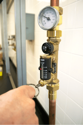
If each circuit is equipped with a device such as a Caleffi Quicksetter valve (seen in Figure 3-4), a flowmeter or a circulator with a digital display, the flow rate can be read directly. If balancing valves with pressure tappings are present, and a compatible manometer is available, the flow rate can be estimated based on the pressure drop across the balancing valve.
There is no specific flow rate that a hydronic circuit must operate at for correct heat transport. Flow rates of approximately one gallon per minute per 10,000 Btu/hr of expected heat transport rate are typical. That flow rate will produce a temperature drop of about 20oF between the supply and return side of the circuit when the supply water temperature is at or close to its design load value. Slightly higher flow rates are fine, provided they do not create flow noise or pipe erosion. For copper tubing, the suggested maximum flow rate for piping routed through occupied spaces is four feet per second. To avoid erosion in copper tubing, the flow velocity should not exceed six feet per second.
Keep in mind that even though the system may operate at a temperature drop of approximately 20oF under design load conditions (e.g., when supplied with water at the design load temperature), it will operate at lower temperature drops when the water temperature supplied to the heat emitters is lower than the design load value, such as when the supply water temperature is regulated by outdoor reset control. One sign of an insufficient flow rate is a high temperature drop between the supply and return side of a circuit. When the supply water temperature is near design conditions, a temperature drop over 25 F is generally an indicator of insufficient flow rate.
Insufficient flow could be caused by several things, including:
• The circulator is too small, or the circulator speed setting is too low
• A zone valve has failed to open.
• A mixing valve with a low Cv is present in the flow path.
• One or more valves in the circuit are partially shut.
• A filter, strainer or other component in the circuit is clogged with debris.
• The circuit was not installed as designed, and now contains significantly more fittings or other devices — especially when all such fittings and devices are piped in series.
• In extreme cold conditions, it’s possible that water in some portion of the circuit is frozen, creating a flow blockage.
STEP 9: Check the condition of the system fluid.
Properly installed closed-loop hydronic systems that are constructed mostly of metal piping components can contain the same water for many years without experiencing corrosion issues. This is possible because the dissolved oxygen molecules in the initial fill water quickly react with ferrous metal in the system (e.g., cast iron or steel) to form thin and essentially harmless oxide films. At that point, the further oxidation potential of the water is minimal. However, no hydronic system is sealed to the point where no oxygen can enter the system through circulator flange gaskets, valve packings or non-barrier polymer tubing.
Systems that experience significant water loss, and corresponding entry of fresh makeup water due to various abnormalities, allow oxygen to be replenished inside the system. This can lead to formation of sludges, such as magnetite or other types of oxygen-fueled corrosion. During servicing, technicians should draw a small sample of system fluid (approximately 1 pint) and examine it for color, smell, consistency and the presence of particles. Water that is slightly gray in color, and has a slight metallic odor, is generally fine. However, water or mixtures of water and antifreeze that are dark brown or black in color, or have a pungent odor, typically indicate oxidation within the system.
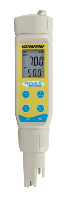
Fluid that is highly viscous in nature and with a dark color often indicates a chemical breakdown of rubber or other non-metals in the system. It could also indicate oxidation of ferrous metal. The presence of fine, dark- colored “grit” (e.g., magnetite) in the fluid is also an indicator of corrosion due to oxidation of ferrous metals. Technicians should use test strips or test meters, such as shown in Figure 3-5, to evaluate the pH of the system fluid. pH values of 7.0 to 8.0 are generally fine. However, low pH values (under 7.0) indicate acidity. This condition is more prevalent in systems using glycol-based antifreeze and operating at high temperatures. The antifreeze eventually breaks down into an acid.
Left unchecked, this condition can cause widespread corrosion in the system. Corrective actions include draining the fluid, internally cleaning the system with a hydronic detergent to remove residue, and refilling with either demineralized water or a mixture of demineralized water and inhibited glycol-based antifreeze. Stabilizer chemicals can also be added to preserve the pH of the fluid.
See idronics #18 for detailed information on water quality in hydronic systems:
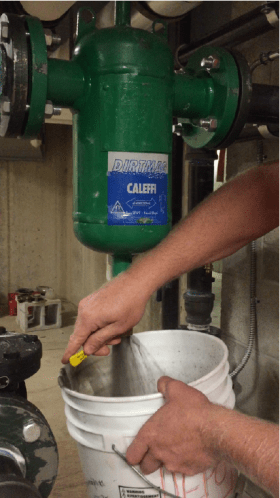
Systems that exhibit dark and gritty fluid should also be fitted with a magnetic dirt separator, such as the Caleffi DIRTMAG® PRO or SEP4™ separator. These devices contain strong magnets that can capture iron oxide particles and allow them to be periodically flushed from the system, as shown in Figure 3-6.
STEP 10: Check the condition of the heat emitters.
The heat emitters in a hydronic system are usually not the underlying cause of “insufficient heating” complaints. However, there are some circumstances where, with all other portions of the system operating normally, the heat emitters could be the source of insufficient heating.
Check for the following on fin-tube baseboard systems:
• Are all dampers on the baseboard housing fully open?
• Is the fin-tube element reasonably clean (not heavily coated with dust or other debris)?
• Have the fins on the element been extensively deformed or damaged?
• Is there air in the baseboard? Listen for “gurgling” or “trickling” sounds, indicating the presence of air.
• Are upholstered furniture, boxes, drapes, shelves or other objects blocking inlet and outlet airflow through the baseboard?
• Are there isolation or zone valves housed inside the baseboard enclosure that may be blocking flow?
Check for the following on panel radiator systems:
• Are the isolation valves at the inlet and outlet of the radiator fully open?
• Is the thermostatic operator on a radiator valve (if present) fully open?
• Does the spring-loaded stem on the radiator valve fully extend when the thermostatic operator is removed?
• Are the convective fins inside the radiator reasonably clean?
• Is there anything blocking convective airflow upward through the radiator fins?
• Is there air in the radiator? Listen for “gurgling” or “trickling” sounds, indicating the presence of air.
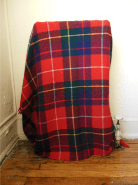
• Are upholstered furniture, boxes, drapes, quilts, shelves or other objects blocking inlet and outlet airflow through the radiator (see Figure 3-7)?
Check the following on systems using air handlers or fan-coils:
• Are there any isolation valves at the inlet and outlet of the air handler’s coil that could be blocking or restricting flow?
• Is there air in the air handler’s coil? Listen for “gurgling” or “trickling” sounds, indicating the presence of air.
• Is there electrical power at the power input terminals of the air handler?
• Are any internal controls within the air handler configured properly?
• Does the blower operate normally?
• Is the air inlet filter reasonably clean?
• Are there any signs of electrical overload on circuit boards or other electrical components? Are there any fuses that might be blown, or internal circuit breakers that might be tripped?
• With the filter removed, are the surfaces of the air handler’s coil reasonably clean?
• Check that the condensate trap (if present) is not clogged.
• Are all air dampers in the ducting system at least partially open?
Check the following on systems using radiant panels:
• Are all manifold valves at least partially open?
• Is there evidence of air in the manifold station? Listen for “gurgling” or “trickling” sounds, indicating the presence of air.
• On manifolds with flow meters, verify the flow rate in each active circuit when the associated circulators are running.
• On floor-heating systems, check that the floor has not been covered with objects such as boxes, furniture, rugs, carpet padding or other objects that could significantly restrict upward heat flow.
• Verify the presence of adequate underfloor insulation. Suggested values for the underside insulation R-value are at least 10x the total R-value of any materials covering the radiant floor panel.
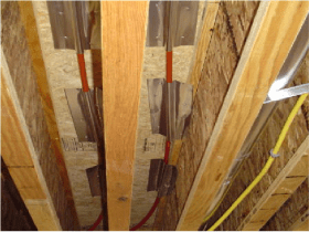
• If the system uses aluminum heat transfer plates installed under a subfloor, be sure that the plates make tight contact with the tubing and tight contact with the underside of the subfloor. Poorly formed or bent plates that create gaps between the tubing and plate surfaces, or between the plate and subfloor, can substantially reduce heat transfer (see Figure 3-8).
FURTHER CONSIDERATIONS
At this point in the troubleshooting procedure, the following functions are assumed to have been checked and verified as operating properly:
• Electrical power (line voltage and 24 VAC) is available to all portions of the system that require these voltages.
• Fuel is available to the heat source at the required pressure.
• All thermostats have been checked and are functioning properly.
• The system is not “air bound.”
• Zone valves or zone circulators are operating normally.
• The heat source operates when any zone thermostat calls for heat.
• The heat source is producing heated water.
• Flow in all active zone circuits is within an acceptable range.
• The heat emitters are reasonably clean and have flow passing through them when the system’s circulator(s) are on.
• There are no valves with broken stems present in the circuit(s).
Assuming that all of the above functions are normal, some heated fluid will be moving through the distribution system and heat emitters. However, the rate of heat transfer, and the locations to which that heat is being delivered, may still not produce acceptable comfort in all areas of the building. This could be the result of inadequate sizing of the heat source, piping, circulators or the heat emitters. It could also be the result of inaccurate load estimating.
WHEN IT’S THE BUILDING, NOT THE HEATING SYSTEM
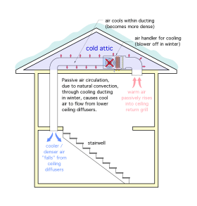
It’s also possible that the underlying cause of inadequate heating is one or more issues with the building, rather than the heating system. Issues may be from failed or missing weather stripping on doors, windows or attic hatches; new penetrations through the building’s thermal envelope for wiring or plumbing; or deteriorated insulation in exterior surfaces due to water leaks. Natural convective air currents through inactive air-conditioning ducting located in unconditioned attics can also create a persistent cooling effect in winter, as illustrated in Figure 3-9.
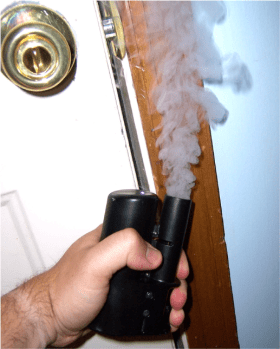
When a problem with the building envelope is suspected as the cause of inadequate comfort, a weatherization specialist may be helpful in identifying the issue(s) using tools such as thermographic imaging (see Figure 3-10), blower doors (see Figure 3-11) and smoke canisters (see Figure 3-12), which can detect very minor air leaks.
In many cases, the source of excessive heat loss (and associated discomfort) can be identified and partially or fully corrected through weatherization processes, such air sealing, new weather stripping or added insulation. These building envelope improvements often have very good returns on investment and can recoup their costs many times over during the life of the building.

