PREFACE
One of the most important design details for successful application of air-to-water heat pumps is keeping the required load water temperature as low as possible. Low load temperatures allow the heat pump to operate at high COPs in heating mode.
Space heating distribution systems that can provide design heating output using supply water temperatures no higher than 120ºF allow the majority of currently available air-to-water heat pumps to deliver reasonably good performance. Systems that can operate at even lower supply water temperatures will further improve heat pump performance.
Distribution systems that supply each heat emitter using parallel piping branches rather than series configurations are also preferred because they provide the same supply water temperature to each heat emitter.
Examples of heat emitters and other techniques that allow air-to-water heat pumps to provide good performance include:
• Heated floors with low-resistance coverings
• Radiant wall and ceiling panels
• Generously sized panel radiator systems
• Fan-assisted panel radiators
• Fan coils (allowing for heating and cooling)
• High-output fin-tube baseboard
• Existing cast iron radiators
• Reducing building heating loads, or adding a heat emitter to existing systems
This article discusses these heat emitter and design options in more detail.
Heated Floor Slabs
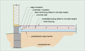
Heated floor slabs with relatively close tube spacing and low finish floor resistances are well-suited for use with air-to-water heat pumps. Figure 6-1 shows a cross section of a heated floor slab.
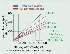
The graph in Figure 6-2 shows upward heat output from a heated slab using tube spacings of 6 inches and 12 inches, and for finish floor resistances ranging from 0 to 1.0 (ºF•hr•ft2/Btu). The steeper the line, the better suited the distribution system is for use with a heat pump.
Figure 6-2 shows that achieving an upward heat output of 20 Btu/hr/ft2 from a slab with no covering (e.g., Rff = 0) and 6-inch tube spacing requires the “driving ∆T” (e.g., the difference between the average water temperature in floor circuit and room air temperature) to be 17.5ºF. Thus, in a room maintained at 70ºF, the average water temperature in the circuit needs to be 87.5ºF. The supply water temperature to the circuit would likely be in the range of 95–98ºF. This is a relatively low supply water temperature that would allow an air-to-water heat pump to operate at high COPs.
For comparison, consider supplying the same 20 Btu/hr/ft2 load using a heated floor slab with 12-inch tube spacing and a finish floor resistance of 1.0ºF•hr•ft2/Btu. The driving ∆T must now be 42.5ºF. The average circuit water temperature required to maintain a room temperature of 70ºF would be 70 + 42.5 = 112.5ºF and the supply temperature likely in the range of 120–123ºF. This higher temperature would significantly reduce the heat pump’s COP.
The following guidelines are suggested in applications where a heated floor slab will be used to deliver heat derived from a hydronic heat pump:
• The tube spacing within the slab should not exceed 12 inches.
• The slab should have a minimum of R-10 underside and edge insulation.
• The tubing should be placed at approximately 1/2 the slab depth below the surface, as shown in Figure 6-1. This placement decreases the required water temperature required for a given rate of heat output relative to tubing placed at the bottom of the slab. Lower water temperatures improve heat pump performance.
• Bare, painted or stained slab surfaces are ideal because the finish floor resistance is essentially zero.
• Any finish flooring layers installed on the slab should have a combined total R-value of 1.0 or less.
Underfloor tube & plate radiant panels
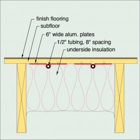
Another possible radiant panel construction is called an underfloor tube & plate system. Figure 6-3 shows a typical cross section for this panel.
This panel provides a way to heat wood-framed floors. It relies on aluminum heat transfer plates to diffuse heat away from the tubing and spread it across the floor area. These plates are critically important for good performance. To achieve compatibility with low water temperatures, tube spacing should not exceed 8 inches.
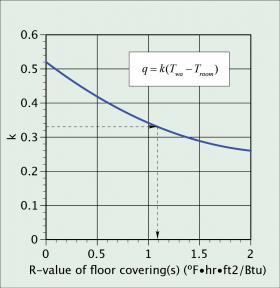
The maximum allowed R-value of the subfloor and finish floor coverings should also be kept as low as possible. Figure 6-4 plots a coefficient called “k,” versus the R-value of finish floor covering installed over a 3/4-inch thick plywood subflooring and assumes 8-inch tube spacing.
The heat output of this floor panel can be estimated using Formula 6-1.
Formula 6-1:
$$q=k(T_{wa} - T_{room})$$
where:
q = heat output of the underfloor tube & plate panel (Btu/hr/ft2)
k = value from Figure 6-4
Twa = average water temperature in tubing circuit (ºF)
Troom = room air temperature (ºF)
A suggested guideline in evaluating floor coverings for this type of radiant panel is to constrain the average water temperature to no higher than 115ºF. This would allow the supply water temperature to be 120ºF (assuming a 10ºF circuit temperature drop). If this constraint is entered into Formula 6-1, a relationship between panel output, room air temperature and allowed finish floor covering resistance is established.
Here’s an example. Assume that a designer has determined that the radiant floor needs to release 15 Btu/hr/ft2 under design load conditions. To achieve good heat pump performance, the designer wants to limit the average water temperature in the panel to 115ºF under design load conditions. What is the maximum thermal resistance of the floor coverings?
Using Figure 6-4, the maximum thermal resistance of the finish floor covering(s) allowable in this situation is R-1.1ºF•hr•ft2/Btu.
Radiant wall panels
Radiant panels can be integrated into walls and ceilings as well as floors. Several of these configurations are suitable for use with air-to-water heat pumps. The key is ensuring that the radiant panel can deliver design load output while operating at a relatively low water temperature. This favors radiant panels that provide high surface areas relative to their rate of heat delivery. It also favors panels that have low internal thermal resistance between the tubing and the surface area releasing heat to the room.
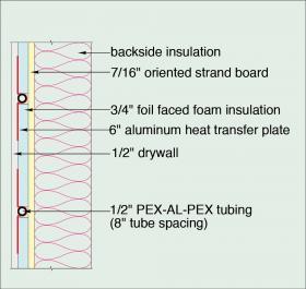
One example is a radiant wall panel constructed as shown in Figure 6-5.
When finished, this “radiant wall” is indistinguishable from a standard interior wall. Its low thermal mass allows it to respond quickly to changing internal load conditions or zone setback schedules. The rate of heat emission to the room can be estimated using Formula 6-2:
$$q=k(T_{wa} - T_{room})= 15 = k(115-70)$$
$$k={15\over (115-70)}=0.333$$
where:
q = heat output of wall panel (Btu/hr/ft2)
Twa = average water temperature in panel (ºF)
Troom = room air temperature (ºF)
Thus, if the radiant wall panel operates with an average water temperature of 110ºF in a room with 70ºF air temperature, each square foot of heated wall would release about 0.8 x (110 - 70) = 32 Btu/hr/ft2.
Radiant Ceiling Panels
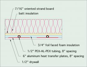
Another possibility is a radiant ceiling panel using the same materials and construction methods as the radiant wall panel. Figure 6-6 shows a cross section of this construction.
In this construction, the 1/2” PEX-AL-PEX tubes are spaced 8 inches apart. The plates are 5 inches wide. The 3/4-inch foil-faced polyisocyanurate foam insulation strips are “held back” near the U-bends in the tubing. A 3/4-inch thick furring board runs adjacent to the upper plate of the partition. This assembly will be covered with 1/2-inch drywall. 2.5-inch long drywall screws will be installed halfway between adjacent tubes and spaced 12 inches apart in the direction parallel with the tubes.
The rate of heat emission to the room can be estimated using Formula 6-3:
$$q= 0.71·(T_{wa} - T_{room}) $$
where:
q = heat output of ceiling panel (Btu/hr/ft2)
Twa = average water temperature in panel (ºF)
Troom = room air temperature (ºF)
Heated ceilings have the advantage of not being covered or blocked by coverings or furniture, and thus, are likely to retain good performance over the life of the building. They are also ideal surfaces for radiant cooling using chilled water supplied from an air-to-water heat pump. However, when radiant cooling is used, it is critical to maintain the chilled water temperature above the dewpoint of the interior air.
More information on radiant cooling is available in idronics #13
Panel Radiators
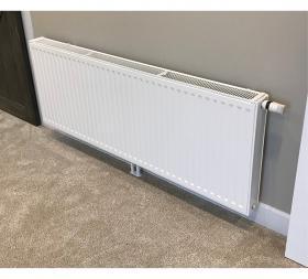
Generously sized panel radiators can also provide good performance when used as part of a hydronic heat pump system. The suggested guideline is to size panels so they can deliver design space heating output using a supply water temperature no higher than 120ºF. An example of a panel radiator with integral thermostatic radiator valve is shown in Figure 6-8.
Panel radiator manufacturer’s provide “reference” output ratings for their panels assuming that they operate at a specific average water temperature and in rooms with a specific air temperature. Correction factors are then given that allow the heat output rate to be adjusted for other average water temperatures and room air temperatures.
As an approximation, a panel radiator similar to the one shown in Figure 6-8, operating with an average water temperature of 110ºF, and in a room with 70ºF air temperature, provides approximately 27% of the heat output it would have at a reference average water temperature of 180ºF and room air temperature of 70ºF. Larger panels (e.g., longer, taller and deeper) are available to increase surface area to compensate for lower average water temperatures. The panel radiator shown in Figure 6-8 will release about 3,400 Btu/hr into a room at 70ºF, when operated at an average water temperature of 110ºF.
Fan-assisted panel radiators
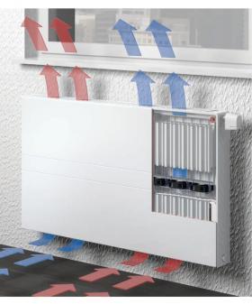
One of the newest low-temperature heat emitters is a fan-assisted panel radiator. These units use an array of small, low-power fans installed between the front and back surfaces of the panel. The fans automatically change speed based on room temperature relative to setpoint. They significantly increase convective heat output at low supply water temperatures. Each fan only requires about 1.5 watts of electrical power at full speed, and thus, electrical energy consumption is negligible, especially when compared to the electrical energy savings associated with operating the heat pump at lower water temperatures and higher COPs.
Fan-assisted panel radiators can operate at water temperatures as low as 95ºF. They have integral controls that can be set for a “boost” mode (e.g., full-speed fan operation) when the system is recovering from a setback temperature.
Fan-coils
One of the benefits offered by air-to-water heat pumps is the ability to create chilled water for warm weather cooling. Successful implementation of hydronic cooling must address sensible cooling (e.g., lowering the temperature of interior air), as well as latent cooling (e.g., lowering the moisture content of interior air). The latter process implies that some of the water vapor in the air must be condensed into a liquid.
Condensation will occur on any surface that is below the dewpoint temperature of the surrounding air. The lower the surface temperature relative to the dewpoint temperature, the faster the rate of condensation. On humid days, the dewpoint of untreated interior air can reach well into the low to mid-70s ºF range. This is much higher than the chilled water temperatures that air-to-water heat pumps can produce, which are often in the range of 45 to 60ºF Panel radiators, fin-tube baseboard and radiant panels are not intended to operate under condensing conditions. Allowing condensation to occur on these heat emitters can quickly lead to water stains, corrosion, mold, and in the case of radiant panels — major damage to the materials making up the panels.
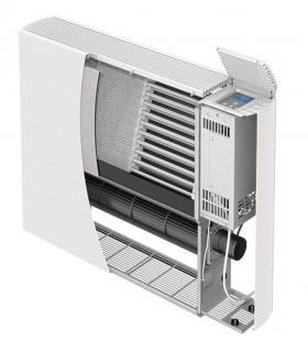
One heat emitter that can serve as a “cooling emitter” as well as a heat emitter is a fan-coil equipped with a condensate drip pan. One example of such a product is shown in Figure 6-10.
This fan-coil combines a large surface “coil” made of copper tubing with aluminum fins, with a low-power tangential blower located under the coil. A drip pan is also located under the blower. It catches water droplets that form on the coil and eventually drip from it. The captured condensate is drained away from the unit by gravity through a small tube and disposed of outside the building or into a suitable drainage system. If no drain is available at a lower elevation than the drip pan, the condensate can be routed to a condensate pump, which will move it upward to a suitable drain.
Modern fan-coils designed for heating and cooling operation can be sized to operate at a relatively low supply water temperature in heating (e.g., 120ºF or less). Their cooling performance is based on the temperature of chilled water supplied to the coil. Lower water temperatures improve both sensible and latent cooling capacity. Designers need to assess the sensible and latent ratings of perspective fan-coils to ensure adequate overall cooling. Heat pump performance (e.g., both cooling capacity and EER) increases as chilled water temperatures increase. To achieve the best heat pump performance, designers should use the highest chilled water temperature that can ensure adequate sensible and latent cooling. Chilled water supply temperatures in the range of 50 to 60ºF are possible with some fan-coils and are well within the operating range of air-to-water heat pumps
Low-Temperature Fin-Tube Baseboard
Fin-tube baseboard was originally developed for the high water temperatures available from conventional boilers. It was often sized for supply water temperatures of 180ºF to 200ºF, and in some cases even higher. This is much higher than the water temperatures air-to-water heat pumps can produce. Thus, traditional fin-tube baseboard is not recommended in such applications.
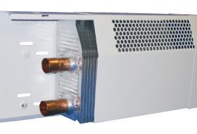
However, as the global hydronics industry moves toward low water temperature distribution systems, some manufacturers have developed “low-temperature” fin-tube convector products. The fin-tube element shown in Figure 6-11 has significantly greater fin area compared to that of a standard element. It also has two tubes passing through the fins. This allows significantly higher heat output at lower water temperatures. The rated output of the fin-tube element in Figure 6-11, with both tubes operating in parallel, is 272 Btu/hr/ft at an entering water temperature of 90ºF, and 532 Btu/hr/ft at a water temperature of 120ºF, both at a total flow rate of 1 gallon per minute.
Cast Iron Radiators
Many older homes have existing cast iron radiators. They may have been part of an original steam heating system, or they might have operated with water.
If the cast iron radiators were originally sized for a poorly insulated or uninsulated building, and that building was subsequently insulated and fitted with new windows and doors or air sealed, the existing radiators may only have to provide a fraction of the heat output for which they were originally sized. This may allow the radiators to operate at a much lower water temperature, such as those available from an air-to-water heat pump.
The heat output of cast iron radiators can be estimated for relatively low average water temperatures. The process requires that the surface area of the radiator be determined based on the radiator’s type and dimensions.
Reducing water temperature in existing systems
There are many “legacy” hydronic heating systems designed to operate at water temperatures much higher than are possible when an air-to-water heat pump serves as the primary heat source. The required water temperature in those systems can be reduced through two methods:
1. Reducing the building’s design heating load.
2. Adding heat emitters to the distribution system.
It is also possible to use a combination of these methods.


