PREFACE
Most air-to-water heat pumps have an outside unit, similar to that of an air-to-air heat pump or central air-conditioning system. However, the heat generated while operating in the heating mode is delivered to a hydronic distribution system within the building. When operating in the cooling mode, air-to-water heat pumps deliver a stream of chilled water, or chilled antifreeze solution, that flows to the balance of the system. The use of a hydronic distribution system for heating and cooling creates many possibilities that are not possible with forced-air distribution systems.
MONOBLOC AIR-TO-WATER HEAT PUMPS
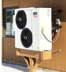
Figure 4-1 shows a modern “monobloc” air-to-water heat pump. The insulated pipes, seen penetrating the building wall behind the unit connect to the interior portion of the system.
When operating, variable-speed fans pull outside air across the air-to-refrigerant heat exchanger on the rear of the unit. In heating mode, this heat exchanger serves as the evaporator. Low-temperature heat is absorbed from the air, and the cooled air is discharged through the fan grills at the front of the unit. In cooling mode, the same heat exchanger serves as the condenser for dissipating heat to outside air.
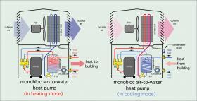
Monobloc air-to-water heat pumps house all the refrigeration system components and most of the electrical controls within the outdoor unit. Some monobloc heat pumps also contain hydronic components such as a circulator, expansion tank or flow verification switch. Monobloc heat pumps are supplied pre-charged with the correct amount of refrigerant, which implies that they can be installed without need of refrigeration service equipment. Figure 4-2 illustrates the basic internal components in a monobloc heat pump as they would operate in heating and cooling modes.
Systems designed with monobloc air-to-water heat pumps vary depending on the severity of the winter climate. In mild climates, where outdoor temperatures below freezing are rare, it is usually acceptable to install the heat pump with water in the piping circuit between the outdoor unit and indoor distribution system. Most heat pumps of this type have a controller that automatically turns on a circulator and an electric heating element when necessary to protect the unit from freezing. These components can add enough heat to maintain the water-filled portion of the heat pump above freezing, even when there is no load calling for heat pump operation.
However, in situations where significant temperature setbacks or prolonged power outage are possible during subfreezing outdoor temperatures, and no backup generator capable of running the heat pump is available, it is advisable to install the unit as part of an antifreeze-protected hydronic circuit. Some manufacturers mandate that antifreeze solutions be used in all installations of their monobloc air-to-water heat pumps.
FREEZE PROTECTION OPTIONS FOR MONOBLOC HEAT PUMPS
All systems designed around monobloc air-to-water heat pump systems need to consider freeze protection. Even systems in southern states could experience a situation in which a prolonged power outage accompanied by subfreezing temperatures could allow water to freeze within the exterior piping and heat exchanger. Another possibility is when the heat pump is not operating due to a service issue while subfreezing temperatures occur.
ANTIFREEZE-BASED PROTECTION
One of the simplest methods of preventing freezing is to fill the entire system with an antifreeze solution of adequate concentration to prevent damage to the system under the coldest expected temperatures. The amount of antifreeze needed depends on the expected function of the solution during cold weather. Is that function to allow flow through the system under the coldest expected temperature, or is it to prevent bursting of one or more components due to expansion of the solution when it freezes solid? This requires differentiation between the freeze point and burst point temperatures.
The freeze-point temperature of an antifreeze solution is the minimum temperature at which the solution remains flowable. Small ice crystals are just beginning to form in the fluid when it drops to its freeze-point temperature. This temperature is well below the normal operating temperature of a typical air-to-water heat pump. However, if it is possible that the heat pump may have to start after being off for several hours in very cold ambient conditions, the antifreeze solution used should have a freeze-point temperature as low as the minimum ambient air temperature at which the cold start could occur.
The burst-point temperature of an antifreeze solution is the lowest temperature at which the piping and piping components that contain the solution will not be subject to expansion forces that could rupture them. The antifreeze solution will be mostly ice crystals when it drops to burst point temperature, and thus, not flowable.
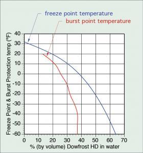
Figure 4-3 compares the freeze protection temperature and burst protection temperature for a range of volumetric concentrations of an inhibited propylene glycol antifreeze.
Based on Figure 4-3, a 35% solution of propylene glycol antifreeze remains flowable down to 5ºF and protects the heat pump and piping against bursting down approximately -30ºF. A 50% solution of the same antifreeze remains flowable down to -20ºF and provides burst protection to temperatures below -60ºF. The objective is to select a concentration that adequately protects the system but doesn’t use excessive amounts of antifreeze. The higher the antifreeze concentration, the higher the viscosity of the fluid, and the greater the flow resistance of the hydronic circuit. Adding antifreeze to water also decreases the heat transfer capacity of the solution. A 50% solution of propylene glycol antifreeze lowers the specific heat of the solution to approximately 90% that of water. This can be compensated for by using higher flow rates, but that can significantly increase circulator power requirements.
Setting up the entire system to operate with an antifreeze solution has advantages and disadvantages. One advantage is the elimination of any heat exchanger between the heat pump and balance of the system. A heat exchanger is required in situations where the heat pump circuit operates with an antifreeze solution while the balance of the system operates on water. The presence of a heat exchanger between the heat pump and balance of the system forces the heat pump to operate at higher temperatures compared to where it would operate without the heat exchanger. This is necessary to create a temperature difference across the heat exchanger that’s adequate to transfer heat from the antifreeze solution to the water at the rate at which the heat pump supplies heat. Operating the heat pump at higher fluid temperatures lowers its COP. This increases the amount of electrical energy required per unit of heat delivered.
Another advantage of operating the entire system with antifreeze is that the entire system is protected in the event of prolonged malfunction or power outage during cold weather.
One disadvantage of adding antifreeze is higher power requirements for circulators relative to those required for water only. A 50% solution of propylene glycol antifreeze requires approximately 60% higher circulator input power to achieve the same heat conveyance rate (e.g., the combined effect resulting from changes in specific heat, viscosity, density and flow rate). Adding antifreeze to systems with large volumes such as those with extensive radiant panel circuits and/or large buffer tanks increases cost. Systems with antifreeze should also be checked annually to ensure that the pH buffers in the antifreeze are adequate to prevent thermal breakdown.
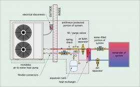
Another option for freeze protection is to add a heat exchanger between the heat pump and remainder of the system. This is illustrated in Figure 4-4. The piping circuit between the heat pump and the primary side of the heat exchanger is filled with an antifreeze solution. The secondary side of the heat exchanger and the balance of the system operate with water.
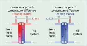
If a heat exchanger will be used, it is essential that it is generously sized. One suggested criterion is to select a heat exchanger that can pass the full rated heat output of the heat pump without exceeding an approach temperature difference of 5ºF, as shown in Figure 4-5.
For heating mode operation, the approach temperature difference is calculated by subtracting the temperature of the water leaving the secondary side of the heat exchanger from the temperature of the antifreeze entering the primary side of the heat exchanger. The greater the internal area of the heat exchanger, the lower the approach temperature difference will be for a given rate of heat transfer. When practical and cost effective, approach temperature differences lower than 5ºF are beneficial.
The use of a heat exchanger between the heat pump and balance of the system also requires two circulators: One between the heat pump and heat exchanger, and the other between the heat exchanger and balance of the system. This adds to installation cost. It also adds to operating cost. Use of high-efficiency ECM-circulators helps minimize the total electrical energy required for pumping.
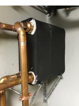
In situations where the heat pump will provide cooling, it is necessary to fully insulate the heat exchanger to prevent surface condensation. Figure 4-6 shows an example of a relatively large brazed plate stainless steel heat exchanger that is used between a nominal 4-ton air-to-water heat pump and the balance of the system.
The heat exchanger shown in Figure 4-6 uses plates measuring 5 inches wide and 12 inches tall. There are 100 plates “stacked” together to make this heat exchanger. It is capable of transferring 60,000 Btu/hr with an approach temperature difference of 5ºF. The heat exchanger is completely wrapped with a layer of 1/2-inch elastomeric foam insulation. The insulation is sealed to the piping at all connections. All piping to and from the heat exchanger will eventually be covered with elastomeric foam pipe insulation and sealed to prevent surface condensation when operating in cooling mode.
SPLIT SYSTEM AIR-TO-WATER HEAT PUMPS
Another common configuration for air-to-water heat pumps is known as a “split system.”
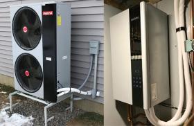
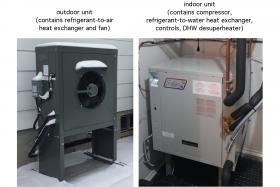
Some of the refrigeration system components are located in the outdoor unit, while the remainder are located inside the building. Two copper tubes transport refrigerant between the inside and outside units. Figure 4-7 shows one example of an outdoor unit and its matching indoor unit. The refrigeration tubing routed between these units is covered with white insulation.
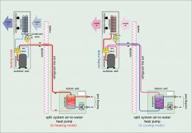
In this system, the compressor is located in the outdoor unit. The indoor unit houses the refrigerant-to-water heat exchanger, as well as the circulator and the user interface.
Figure 4-8 illustrates the major components in a split system air-to-water heat pump as they would operate in heating and cooling modes. These illustrations show a circulator integrated into the heat pump’s interior unit. Some heat pumps provide this circulator, while others do not.
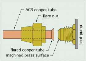
Split system air-to-water heat pumps require refrigeration service tools to install. A typical installation involves running the ACR copper tubing lines between the indoor and outdoor units. The larger tube is called the suction line and the smaller tube is called the liquid line. They typically connect to the indoor and outdoor units using flared joints, as illustrated in Figure 4-9.
After the copper tube set has been connected, it needs to be pressure tested to verify that no leaks are present. This is usually done by introducing compressed nitrogen into the tubing until the internal pressure reaches 250 psi. The system should remain under this test pressure for at least an hour while a technician checks for leaks. Any leaks must be repaired and the pressure test repeated until the system test pressure remains stable for at least one hour.
The next step is to release the test nitrogen and connect a vacuum pump to the system. The vacuum pump is used to remove essentially all gases and moisture from the refrigeration tubing. The vacuum pump typically connects to the refrigeration service valves on the outdoor unit. It is operated until the vacuum level inside the tubing drops to 50 microns. One micron is the very small absolute pressure needed to raise a column of mercury 1/1000th of a millimeter in height.
The outdoor unit of modern split system heat pumps is factory charged with refrigerant. The amount of factory-charged refrigerant corresponds to some maximum allowed length for the refrigeration tubing set between the indoor and outdoor units. Maximum allowed lengths in the range of 15 to 30 feet are common. If the refrigeration tubing set is longer, more refrigerant must be added to the system.
Once the refrigerant tubing has been brought to the required vacuum, the service valves on the outdoor unit are opened to allow the factory-charged refrigerant to fill the remainder of the refrigeration system components. The refrigeration system is now ready to operate.
Currently, the most commonly used refrigerant in residential heat pumps is R410a. Speculation exists that R410a will eventually be replaced by other refrigerants that have less effect on the atmosphere (e.g., lower global warming potential). These include carbon dioxide (CO2), propane and other hybrid mixtures. Given the amount of currently installed systems operating on R410a, it’s very likely that at least some future refrigerants will allow “drop-in” replacement for R410a, if and when as it is phased out.
Split system heat pumps have the advantage that no water or water-based antifreeze solutions are used in the outdoor portions of the system. There is nothing in the outdoor portion of the system that can freeze. All components containing water are housed in the indoor unit.
In some split system air-to-water heat pumps the compressor is housed in the outdoor unit. This reduces interior sound levels. In other split system configurations, the compressor is housed in the interior unit. The latter approach minimizes the number of components in the outside unit, which allows for easier servicing during inclement weather, and likely extends the average service life of components that would otherwise be housed in the outside unit. Figure 4-10 shows an example of a split system air-to-water heat pump with an interior compressor.
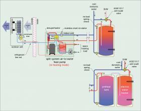
Split system heat pumps with interior compressors also allow the possibility of adding a desuperheater heat exchanger to the indoor unit. The desuperheater is used to heat domestic water by absorbing heat from the hot refrigerant gas leaving the compressor before that gas reaches the reversing valve or condenser. Figure 4-11 shows how a desuperheater is used in this type of heat pump.
Because it receives hot refrigerant gas directly from the compressor, the desuperheater is able to heat domestic water whenever the compressor is running, in heating or cooling mode. In cooling mode, heat transferred to domestic water is heat that would otherwise be wasted by dissipation from the condenser coil into outside air. As such, it is “free” heat. Some heat pumps have controls that limit the domestic hot water temperature produced by the desuperheater to approximately 130ºF. When the water leaving the desuperheater reaches this temperature, the small stainless steel circulator inside the heat pump’s indoor unit turns off. The hot refrigerant gas leaving the compressor just passes through the desuperheater and flows on to the reversing valve and condenser.
Some designers prefer to use two domestic water tanks in systems where the heat pump has a desuperheater. The tank that receives the cold domestic water is a “preheat” tank. The cooler water in this tank circulates through the heat pump’s desuperheater, allowing it to operate at a lower temperature. This improves the heat pump’s performance, especially in systems where the hydronic distribution system operates at low water temperatures. Warm water from the preheat tank flows into the electric water heater whenever there’s a draw of domestic hot water. The elements in the electric water heater operate, if necessary, to raise the water to the desired setpoint temperature. An ASSE 1017-rated thermal mixing valve should always be installed to ensure that the water temperature sent to the hot water fixtures doesn’t exceed 120ºF.
INTERIOR AIR-TO-WATER HEAT PUMPS
There are also air-to-water heat pumps that are designed to be located inside buildings. They use short lengths of ducting to bring outside air to their air-handling section, as well as to discharge that air back outside.
Having the heat pump inside has the following advantages:
• There is no outdoor equipment beyond air intake and discharge grills on the side of the building
• A desuperheater can be incorporated for domestic water heating
• The system can be operated without antifreeze
• Degradation of equipment due to weather exposure is eliminated
• There is less potential for debris to collect on heat transfer coil surfaces
Disadvantages of interior air-to-water heat pumps include:
• Require more interior space
• Brings compressor sound inside the building
• Requires careful coordination with building design to ensure that adequately sized ducting can be accommodated and terminated above snow level.
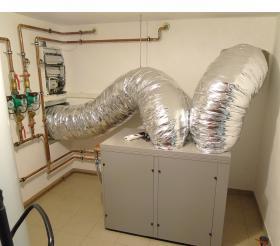
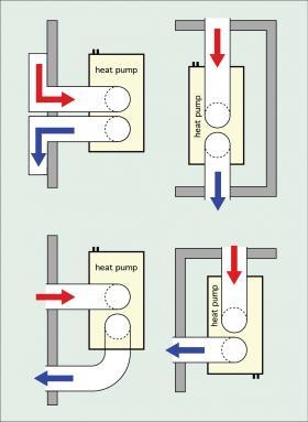
Figure 4-12 shows an example of an interior air-to-water heat pump. The large diameter insulated flexible ducting brings outdoor air to the unit and exhausts it back outside.
It’s important to locate the air intake and discharge openings to prevent cross flow of discharge air into the intake opening.
Manufacturers of interior air-to-water heat pumps typically specify minimum separation distances and provide options such as exterior hoods specifically designed to eliminate crossflow. Some possible options are shown in Figure 4-13.
Interior air-to-water heat pumps are currently offered in Europe, but as of this writing, are not available in North America.
OTHER AIR-TO-WATER HEAT PUMP SYSTEM CONFIGURATIONS
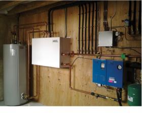
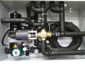
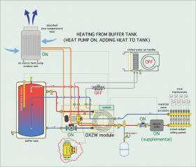
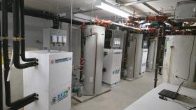
The white box mounted to the mechanical room wall is the “hub” of this air-to-water heat pump system. It connects to the buffer tank, the outdoor condenser unit and the hydronic distribution system. It contains a refrigerant-to-water heat exchanger, a motorized mixing valve, a circulator and a suction line accumulator (for the refrigerant circuit). Figure 4-15 shows how the internal components of this “hub” interface with the surrounding equipment.
As shown in Figure 4-15, the refrigeration system is on. Hot refrigerant gas is circulating from the outdoor unit through the refrigerant-to-water heat exchanger, which is functioning as the condenser. Heated water is flowing into the buffer tank.. Heated water is also being extracted from one of the upper connections on the buffer tank and routed through the 3-way mixing valve to the radiant panel distribution system. This water flows through an electric boiler which may or may not be operating as a supplemental heat source depending on the required supply water temperature to the radiant panel circuits.
This system can also provide chilled water for cooling. The coldest chilled water is passed to the air handler, where it provides some sensible cooling and dehumidification. Slightly warmer chilled water is provided to the radiant panel circuits for added sensible cooling. The motorized mixing valve in the “hub” maintains the temperature of the chilled water flowing to the radiant panel circuits above the dewpoint temperature of the space being cooling. This prevents surface condensation on the radiant panel.
This approach has also been used to construct multiple stage air-to-water heat pump systems to provide space heating, cooling and domestic water heating for multi-family housing buildings. Figure 4-16 shows one example where three 2-stage air-to-water heat pump “hubs” connect to three buffer tanks. Each of these hubs connects to two independently controlled outdoor condenser units.
INTEGRATED SYSTEMS
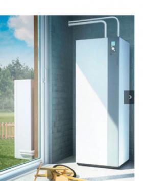
In addition to monobloc, split systems, interior heat pumps and “hub” configurations, some manufacturers supply integrated air-to-water heat pumps. These “appliance” products contain all the hardware necessary to provide heated water for space heating, chilled water for space cooling, and heat for domestic hot water. They also contain electric resistance heating elements that can provide supplemental heating when necessary. Figure 4-17 shows an example of the components used in one of these systems.


